Week-7 Challenge: DC Motor Control
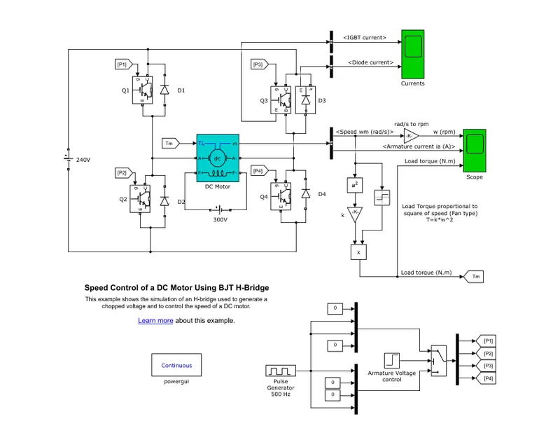
1. A. Explain a MATLAB demo model named ‘Speed control of a DC motor using BJT H-bridge’.
B. Comment on the armature current shoot-up from the scope results.
DC motor using BjT H-bridge :
- Open the matlab and in the help block finding 'Speed control of a DC motor using BJT H-bridge'. A simulink model will open.
- The bipolar junction transitor (BjT) when used for power switching applications, Operates as a IGBT. when it is conducting (BjT opearting in the saturated region), a forward voltage Vf is developed between conductor and emitter. Therefore the IGBT block can be used to model the BjT.
- The H-bridge consists of BjT/ diode pairs. Two transistors are switched simultaneously Q1 and Q4 or Q2 and Q3. When Q1 and Q4 are fired a positive voltage is applied to the motor and the diodes D2-D3 operate as free wheeling diodes. When Q1 and Q4 are swicted off. when Q2 and Q3 are fired a negative voltage is applied to the motor and the diodes D1-D4 operates as free wheeling diodes. When Q2 and Q3 are swicted off.
- IGBT blocks does not simulate the gate current controlling the BjT and IGBT. The switch is controlled by a simulink signal. The DC motor uses the present model. It stimulates a fan type load. The armature mean voltage can be varried from 0 to 240v. when the duty cycle is varried from 0 to 100%.
OUTPUT :
This is the scope block after running the default model to examine the shoot up in the armature block.
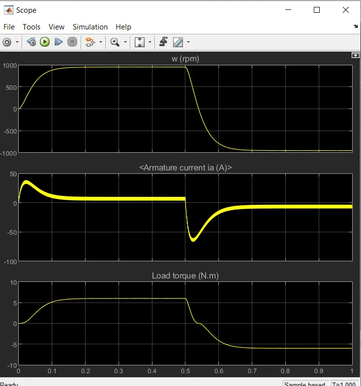
- We can see that there is a shoot up in armature current after 5 second then the motor suddenly changes from forward to reverse motion. The default duty cycle is 75%.
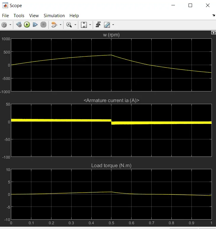
- In the above scope block the duty cycle has changed from 75% to 45%. Now the armature current have shoot up is reduced. As the average duty cycle is reduced to 45%.
C. Refer to the help section of ‘The Four-Quadrant Chopper DC Drive (DC7) block’. Compare it with the H-bridge model.
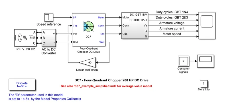
- The 200hp DC motor is seperately excited with a constant 150v dc field voltage source. The armature voltage is provided by an IGBT converter control by two Pi regurlators. The converter is fed by a 515v DC bus obtained by a rectification of a 380v AC 50hz voltage source.
- The first regulaor is a speed regulator followed by a current regulator. The speed regulator outputs the armature current reference used by the current controller in order to obtain the electro magnetic path needed to reach the desired speed.
- The control regulator controls the armature current by computing the appropriate duty ratios of the 5khz pulses of the 4 IGBT devices. For proper system behavior, the instantanous pulse values of IGBT devices 1 and 4 are opposite to those of IGBT device 2 and 3. This generates the average armature voltage needed to obtain the desired armature current.
Four quadrant chopper DC drive :
- The direction of the motor can be changed by changing the polarity.
- It has broader torque and power output ranges.
- Upto 400v can be achieved.
- The current has chopped values and the regenerative braking is possible.
H-bridge :
- The direction of the motor can be changed by changing the current signal by interupting.
- It uses single pulse generator which gives narrow torque and power output range.
- Upto 350v can be achieved.
- The current has continous values and the regenerative braking is not possible.
OUTPUT :
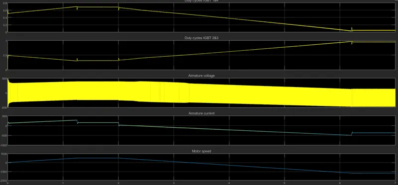
This is the scope block after running the default model.
2) Develop a 2-quadrant chopper using simulink & explain the working of the same with the relevant results. (Refer to article - Multiquadrant operation of motor )
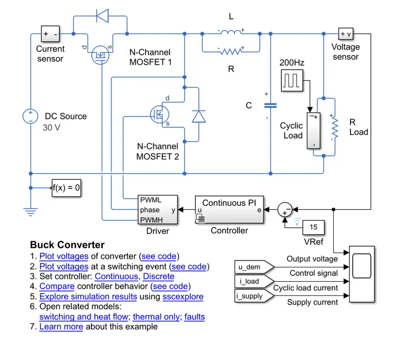
- Open the matlab and in the help block finding 'Buck converter'. A simulink model will open.
OUTPUT :
- This is the scope block after running the default model.
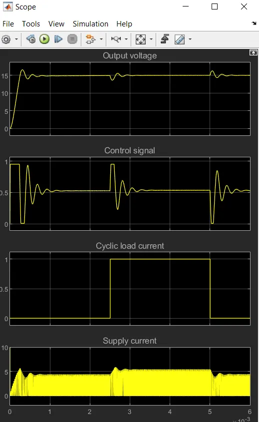
- In the output voltage there is a steady increase in current. The voltage is constant for 2.5sec and there is a difference when the cyclic load current is applied.
- The cyclic load current is for 2.5 sec to 5 sec then the cyclic load comes to constant to 0. The cyclic current is contant.
3) Explain in a brief about operation of BLDC motor.
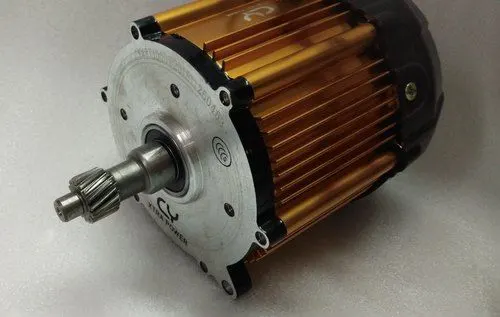
- A brushless DC electric motor also known as electronically commutator motor or synchronous DC motor, is a synchronous motor using direct current. It uses an electronic closed loop controller to switch DC currents to the motor windings producing magnetic field which effectively rotate in space and which the permanent magnet rotor follows.
- The controller adjusts the phase and amplitude of the DC current pulses to control the speed and torque of the motor. The control system is an alternative to the mechanical commutators used in many conventional electric motors.
- The contruction of brushless motor system is typically similar to a permanent magnet synchronous motor but can also be a switch reluctance motor or an induction motor. They may also use neodumium magnets and the outrunners in runners or axles.
- The advantage of a brushless motor over brushed motor are high power to weight ratio, high speed, nearly instaneous control of speed and torque, high efficiency, low maintenance.
- Brushless motors find the applications in such places as computer peripherals, hand held power tools, and vehicles ranging from model aircrafts to automobiles. In modern washing machines brushless dc motor have allowed replacement of rubber belts and gear boxes.