Week-7 Challenge: DC Motor Control
AIM: To study the control of DC Motor
OBJECTIVES:
- Explain a MATLAB demo model named ‘Speed control of a DC motor using BJT H-bridge’.
- Comment on the armature current shoot-up from the scope results.
- Refer to the help section of ‘The Four-Quadrant Chopper DC Drive (DC7) block’. Compare it with the H-bridge model.
- Develop a 2-quadrant chopper using Simulink & explain the working of the same with the relevant results. (Refer to article – multi-quadrant operation of motor)
- Explain in a brief about operation of BLDC motor.
Introduction:
Transistor:
A transistor is a semiconductor device used to amplify or switch electronic signals and electrical power. It is composed of semiconductor material usually with at least three terminals for connection to an external circuit. A voltage or current applied to one pair of the transistor's terminals controls the current through another pair of terminals. Because the controlled output power can be higher than the controlling input power, a transistor can amplify a signal. Most transistors are made from very pure silicon, and some from germanium, but certain other semiconductor materials are sometimes used.
A transistor can use a small signal applied between one pair of its terminals to control a much larger signal at another pair of terminals. This property is called Gain. It can produce a stronger output signal, a voltage or current, which is proportional to a weaker input signal and thus, it can act as an Amplifier. Alternatively, the transistor can be used to turn current on or off in a circuit as an Electricity-Controlled Switch, where the amount of current is determined by other circuit elements.
Power Transistors:
Power transistors may be classified into three types. They are,
- IGBT
- MOSFET
- BJT
IGBT: (Insulated Gate Bipolar Transistor)
IGBT is a three-terminal power semiconductor device primarily used as an electronic switch, which, as it was developed, came to combine high efficiency and fast switching. It consists of four alternating layers (P–N–P–N) that are controlled by a metal–oxide–semiconductor (MOS) gate structure.
Although the structure of the IGBT is topologically the same as a thyristor with a "MOS" gate (MOS-gate thyristor), the thyristor action is completely suppressed, and only the transistor action is permitted in the entire device operation range. It is used in switching power supplies in high-power applications: variable-frequency drives (VFDs), electric cars, trains, variable-speed refrigerators, lamp ballasts, arc-welding machines, and air conditioners.
IGBT can be used to block the negative voltages. It doesn’t have the secondary breakdown problem and, does have high input impedance and low ON state power loss.
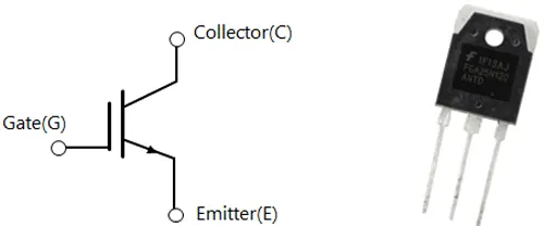
Fig. a, IGBT symbol and Practical model.
MOSFET: (Metal Oxide Semiconductor, Field Effect Transistor)
A power MOSFET is a specific type of metal–oxide–semiconductor field-effect transistor (MOSFET) designed to handle significant power levels. Compared to the other power semiconductor devices, such as an insulated-gate bipolar transistor (IGBT) or a thyristor, its main advantages are high switching speed and good efficiency at low voltages. It shares with the IGBT an isolated gate that makes it easy to drive. They can be subject to low gain, sometimes to a degree that the gate voltage needs to be higher than the voltage under control.
The power MOSFET is the most common power semiconductor device in the world, due to its low gate drive power, fast switching speed, easy advanced paralleling capability, wide bandwidth, ruggedness, easy drive, simple biasing, ease of application, and ease of repair. In particular, it is the most widely used low-voltage (less than 200 V) switch. It can be found in a wide range of applications, such as most power supplies, DC-to-DC converters, low-voltage motor controllers, and many other applications.
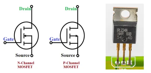
Fig. b, Power MOSFET symbols and Practical model.
In field-effect transistors (FETS), depletion mode and enhancement mode are two major transistor types, corresponding to whether the transistor is in an ON state or an OFF state at zero gate-source voltage.
Enhancement-mode MOSFETS (metal–oxide–semiconductor FETs) are the common switching elements in most integrated circuits. These devices are off at zero gate–source voltage. NMOS can be turned on by pulling the gate voltage higher than the source voltage, PMOS can be turned on by pulling the gate voltage lower than the source voltage. In most circuits, this means pulling an enhancement-mode MOSFET's gate voltage towards its drain voltage turns it ON.
In a depletion-mode MOSFET, the device is normally ON at zero gate–source voltage. Such devices are used as load "resistors" in logic circuits (in depletion-load NMOS logic, for example). For N-type depletion-load devices, the threshold voltage might be about –3 V, so it could be turned off by pulling the gate 3 V negative (the drain, by comparison, is more positive than the source in NMOS). In PMOS, the polarities are reversed.
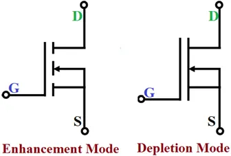
Fig. c, Enhancement and Depletion mode symbols of MOSFET.
BJT: (Bi-Polar Junction Transistor)
A bipolar junction transistor (BJT) is a type of transistor that uses both electrons and electron holes as charge carriers. In contrast, a unipolar transistor, such as a field-effect transistor, uses only one kind of charge carrier. A bipolar transistor allows a small current injected at one of its terminals to control a much larger current flowing between two other terminals, making the device capable of amplification or switching.
BJTs use two junctions between two semiconductor types, n-type and p-type, which are regions in a single crystal of material. The junctions can be made in several different ways, such as changing the doping of the semiconductor material as it is grown, by depositing metal pellets to form alloy junctions, or by such methods as diffusion of n-type and p-type doping substances into the crystal. The superior predictability and performance of junction transistors soon displaced the original point-contact transistor. Diffused transistors, along with other components, are elements of integrated circuits for analog and digital functions. Hundreds of bipolar junction transistors can be made in one circuit at very low cost.
Bipolar transistor integrated circuits were the main active devices of a generation of mainframe and mini computers, but most computer systems now use integrated circuits relying on field effect transistors. Bipolar transistors are still used for amplification of signals, switching, and in digital circuits. Specialized types are used for high voltage switches, for radio-frequency amplifiers, or for switching heavy currents.
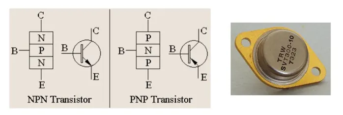
Fig. d, BJT Symbols and Practical model.
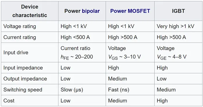
Fig. e, Comparison between Power BJT, Power MOSFET and IGBT.
-----------------------------------------------------------------------------------------------------------------------------------------------------------
Speed Control of DC Motor using BJT H – Bridge:
Main Diagram and Description:
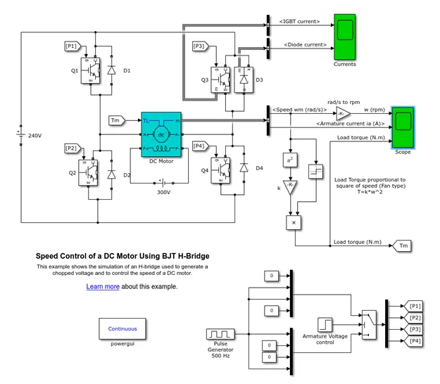
Fig. 1.1, Model Diagram of ‘Speed Control of a DC Motor using BJT H-Bridge.
The BJT when used for power switching applications, operates as an IGBT. When it is conducting (BJT operating in the saturated region), a forward voltage Vf is developed between collector and emitter (in range of 1V). Therefore, the IGBT block can be used to model the BJT device.
The IGBT block does not simulate the gate current controlling the BJT or IGBT. The switch is controlled by a Simulink signal (1/0). The DC motor uses the preset model (5 HP 24V 1750RPM). It simulates a fan type load (where Load Torque is proportional to square of Speed). The armature mean voltage can be varied from 0 to 240 V when the duty cycle (specified in the Pulse Generator block) is varied from 0 to 100%.
The H-Bridge consists of four BJT/Diode pairs (BJT simulated by IGBT models). Two transistors are switched simultaneously: Q1 and Q4 or Q2 and Q3. When Q1 and Q4 are fired, a positive voltage is applied to the motor and diodes D2-D3 operate as free-wheeling diodes when Q1 and Q4 are switched off. When Q2 and Q3 are fired, a negative voltage is applied to the motor and diodes D1-D4 operate as free-wheeling diodes when Q2 and Q3 are switched off.
Pulse Generator Block:
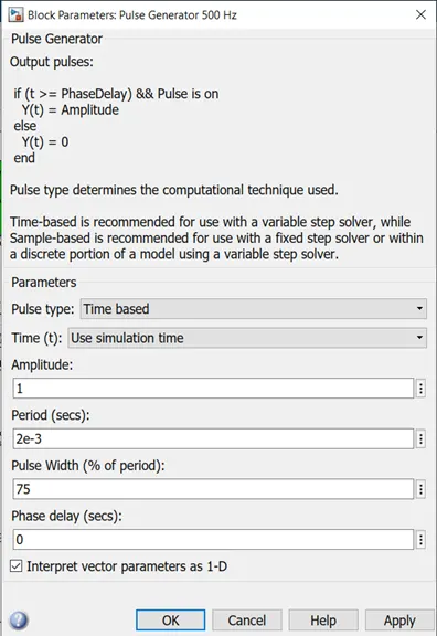
Fig. 1.2, Pulse Generator 500Hz
As we can see, the pulse generator is already preset with some default settings. The pulse width field allows us to modify the duty cycle of the motor and hence, we can prevent the motor current from shooting up when the motor changes its direction from forward to reverse. By default, the duty cycle is 75%, meaning that the voltage is supplied to the motor for 75% of the time for one cycle. For the remaining 25%, the motor is off and receives no voltage from the source. It is this alternation between the ON and OFF states, that allows us to vary the voltage that is supplied to the motor and thereby control the speed of an electric vehicle.
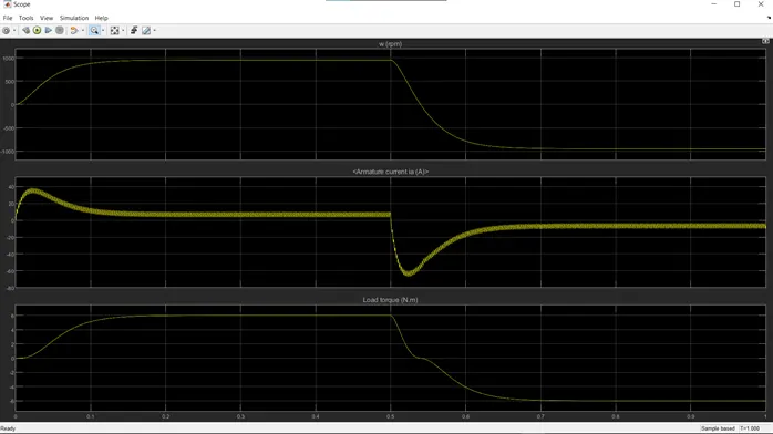
Fig. 1.3, Output with default settings.
In the above figure, there are three graphs which reads Speed, Armature current and Load Torque all against Time axis. We can observe that at beginning of the forward cycle in Armature current, there’s a spike and gradually goes down to a stable value till 0.5 secs, which is the time slot for switching to reverse bias. We can observe there’s a current shoot up at 0.5sec, but in reverse direction. And, our aim is to reduce or eliminate this shoot up as it can cause damage to the peripherals connected to the power source.
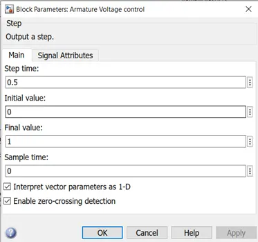
Fig. 1.4, Armature Voltage Control Block.
In order to reduce armature current shoot up, we try to change the pulse width percentage until we find the right value.
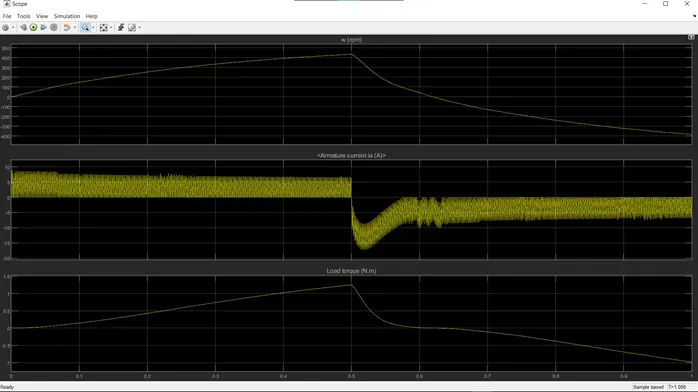
Fig. 1.5, Output at 50% Duty Cycle
Here, we changed the pulse width percentage i.e., Duty Cycle, to 50% from 75%. We can observe a slight decrease in the current shoot up at the reverse switching time.
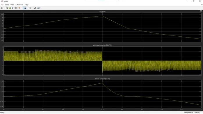
Fig. 1.6, Output at 25% Duty Cycle.
Now the pulse width is set to 25% and we can see no current shoot ups, neither at the beginning nor during reverse bias switching time. So, we can say, as we reduce the duty cycle the armature current shoot up reduces, though it’s not efficient.
Four – Quadrant Chopper Drive:
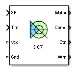
Fig. 1.7, DC7 Block
The Four-Quadrant Chopper DC Drive (DC7) block represents a four-quadrant, DC-supplied, chopper (or DC-DC PWM converter) drive for DC motors. This drive features closed-loop speed control with four-quadrant operation. The speed control loop outputs the reference armature current of the machine. Using a PI current controller, the chopper duty cycle corresponding to the commanded armature current is derived. This duty cycle is then compared with a sawtooth carrier signal to obtain the required PWM signals for the chopper.
The main advantage of this drive, compared with other DC drives, is that it can operate in all four quadrants (forward motoring, reverse regeneration, reverse motoring, and forward regeneration). In addition, due to the use of high switching frequency DC-DC converters, a lower armature current ripple (compared with thyristor-based DC drives) is obtained. However, four switching devices are required, which increases the complexity of the drive system.
The Four-Quadrant Chopper DC Drive block uses these blocks from the Electric Drives/Fundamental Drive Blocks library:
- Speed Controller (DC)
- Regular Switch
- Current Controller (DC)
- Chopper
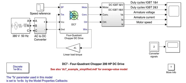
Fig. 1.8, Simulation Diagram of DC7 – Four Quadrant Chopper 200HP DC Drive
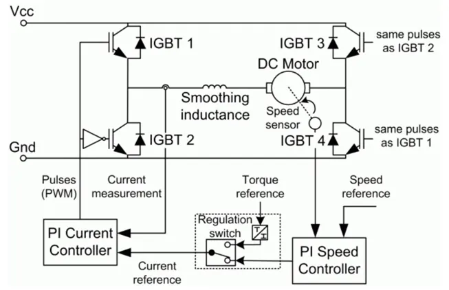
Fig. 1.9, Circuit diagram of Four – Quadrant Chopper DC Drive.
The machine is separately excited with a constant DC field voltage source. There is thus no field voltage control. By default, the field current is set to its steady-state value when a simulation is started.
The armature voltage is provided by an IGBT converter controlled by two PI regulators. The converter is fed by a constant DC voltage source. Armature current oscillations are reduced by a smoothing inductance connected in series with the armature circuit.
Working of Four Quadrant DC Chopper:
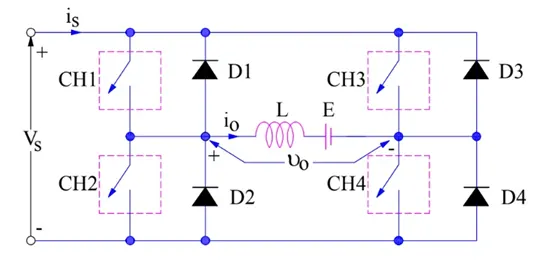
Fig. 1.10, Circuit Diagram of a 4 – Quadrant DC Chopper
In the above circuit, the class E chopper consists of 4 switches CH1 to Ch4 and 4 Diodes D1 to D4 which are connected anti – parallelly. For first quadrant, CH1 is ON and for second quadrant CH2 is ON and so on. To better understand the working of 4 Quadrant Chopper, let’s discuss the operation for each quadrant separately.
First Quadrant:
For first quadrant operation, CH4 is kept ON, Ch3 is kept OFF and CH1 is operated. When both CH1 & CH4 are ON simultaneously, the load gets directly connected to the source and hence the output voltage becomes equal to the source voltage. This essentially means that v0 = vs. It may be noted that the load current flows from source to load as shown by the direction of i0.
When CH1 is switched OFF, the load current free wheels through CH4 and D2. During this period, the load voltage and current remains positive.
Thua, both the output voltage vs and load current i0 are positive and hence, the operation of chopper is first quadrant. It may be noted that, Class-E chopper operates as a step – down chopper in this case.
Second Quadrant:
To obtain second quadrant operation, CH2 is operated while keeping the CH1, CH3 & CH4 OFF. When CH2 is ON, the DC source in the load drives current through CH2, D4, E and L. Inductor L stores energy during the ON period of CH2.
When CH2 is turned OFF, current is fed back to the source through D1, D4. It should be noted at this point that (E+Ldi/dt) is more than the source voltage vs. As load voltage v0 is positive and I0 is negative, it is second quadrant operation of chopper. Since, the current is fed back to the source, this simply means that load is transferring power to the source. Kindly read step up chopper for detailed analysis and better understanding.
For second quadrant operation, load must contain emf E as shown in the circuit diagram. In second quadrant, configuration operates as a step-up chopper.
Third Quadrant:
To obtain third quadrant operation, both the load voltage and load current should be negative. The current and voltages are assumed positive if their direction matches with what shown in the circuit diagram. If the direction is opposite to what shown in the circuit diagram, it is considered negative. One important thing to notice is that the polarity of emf E in load must be reversed to have third quadrant operation. Circuit diagram of Class- E chopper for third quadrant operation is shown below.
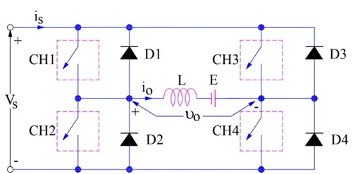
Fig. 1.11, Polarity of the Load EMF E is reversed.
For third quadrant operation, CH1 is kept off, CH2 is kept ON and CH3 is operated. When CH3 is ON, load gets connected to source and hence load voltage is equal to source voltage. But carefully observe that the polarity of load voltage v0 is opposite to what shown in the circuit diagram. Hence, v0 is assumed negative. Let us now see what is the status of load current io. It may be seen that io is flowing in the direction opposite to shown in the circuit diagram and hence negative.
Now, when CH3 is turned OFF, the negative load current free wheels through the CH2 and D4. In this manner, v0 and i0 both are negative. Hence, the chopper operates in third quadrant.
Fourth Quadrant:
To obtain fourth quadrant operation, CH4 is operated while keeping CH1, CH2 and CH3 OFF. The polarity of load emf F need to be reversed in this case too like third quadrant operation.
When CH4 is turned ON, positive current flows through CH4, D2, L and E. Inductance L stores energy during the time CH4 is ON. When CH4 is made OFF, current is fed back to the source through diodes D2, D3. Here load voltage is negative but the load current is always positive. This leads to chopper operation in fourth quadrant. Here, power is fed back to the source from load and chopper acts as a step-up chopper.
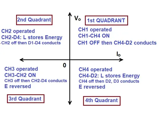
Fig. 1.12, 4 quadrant operation Class – E chopper.
Advantages:
- 4 quadrant choppers have more control over the deceleration of the motor and can accurately brake the motor. This will make the deceleration smoother.
- It reduces the risk of current spikes (and possibly damage the motor and the controller) which can occur when the motor is made to brake while running at a high speed. So, the controller life is generally longer with 4 quadrant choppers.
- 4 quadrant choppers are more efficient because lesser energy is wasted as heat and lesser current spikes occur which means lesser power dissipation.
- It makes regenerative possible so that when the motor is made to brake, the kinetic energy of the rotor moving is transferred back as electrical energy which can then be used to charge a battery.
Comparison with H-Bridge:
Both BJT H- Bridges and 4 quadrant choppers have their advantages and disadvantages.
- H-Bridges like the 4 quadrant choppers are also capable of the braking operation without using air resistance or friction or physical brakes to bring the motor to test.
- 4 quadrant DC Choppers are more commonly used in automobiles whereas BJT H- Bridges are commonly used in robotics and electro – mechanical devices.
- Unlike 4 quadrant DC Choppers, BJT H- Bridges are not capable of performing regenerative braking but they can perform dynamic braking. It is this difference that makes 4 quadrant DC Choppers useful in hybrid and EVs.
- In 4 quadrant DC choppers, the current signals are interrupted with one another to change the direction of rotation of the motor. This is done by a speed reference or a drive cycle from which the speed values are converted to current signals which interrupt one another to change the rotation of direction of the motor. However, in BJT H-bridges, the polarity of the current is reversed (depending on the duty cycle) to change the direction of rotation of the motor.
- Also, the current signals in 4 quadrant DC choppers are chopped meaning that they are not continuous, they are discrete and so take less time for simulations. But in BJT H-bridges, the current values are not chopped, meaning that they are continuous and so take more time for simulations.
- Finally, in 4 quadrant DC choppers, a PI controller is used to control the speed and the current and, in the H-bridge, this is not implemented.
2 – Quadrant Chopper using Simulink:
Operation of 2 quadrant chopper circuit:
- This type of chopper consists of two electronic switches namely, CH1 and CH2 and, two diodes FD and D2 where FD is a free-wheeling diode.
- The two switches should not be turned ON simultaneously as the combined action may cause a short circuit in supply lines.
- This type of chopper is used for regenerative braking and motoring.
- The output voltage V0 is always positive as the freewheeling diode FD is present across the load.
- When the chopper CH1 is ON, the current flows from source to load. The inductor stores energy.
- When CH1 turn OFF, the freewheeling diode starts conducting and output voltage V0 will be equal to Vs.
- The direction of the load current I0 will be reversed. And, the current I0 will be flowing towards the source.
- The load current will be negative when the CH2 is ON. The current completes its path through diode D2.
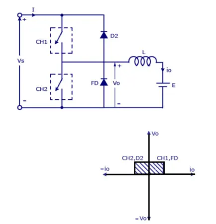
Fig. 2.1, Circuit diagram and graph of 2-Quadrant Chopper.
Two Quadrant Chopper Model using Simulink:
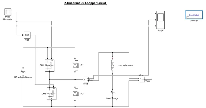
Fig. 2.2, Simulink Model of 2-Quadrant Chopper.
- As we know the 2 – Quadrant Chopper circuit mainly consists of 2 switches and 2 diodes. So, here we’re taking 2 MOSFETs as they’re more efficient and have more capacity compared to other switches. These are denoted as CH1 and CH2. And, these are Simulink blocks rather than Simscape elements.
- Two Diodes with resistances are connected in each other and parallel to the MOSFETs as shown in the fig. 2.2.
- A DC Voltage source is connected as shown in the figure with the amplitude of 24V.
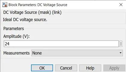
Fig. 2.3, DC Voltage Source.
- Let’s consider a RLC branch block and select Inductor L in the options. Thus, working as a Load.
- This inductor load is connected series to a Load Voltage with an amplitude of 12V. Thus, making a LE Load.
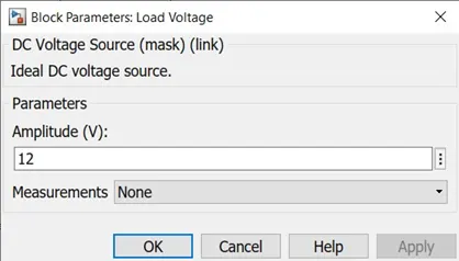
Fig. 2.4, Load Voltage.
- A pulse generator is connected to the Gate Terminals of the two MOSFETs to generate gate pulses. And, it’s made sure that a NOT gate is connected between one of the switches and the pulse generator.
- The NOT gate is connected so that when one switch is ON state, the other remains in OFF state. Otherwise, if the both the switches are in ON state at a time, it will lead to short circuit.
- The amplitude of the pulse generator is kept at 10, the period is set to 0.02 secs and let the pulse width be 50%.
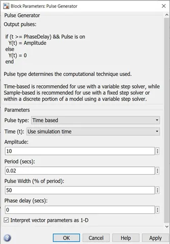
Fig. 2.5, Pulse Generator.
Scope Result:
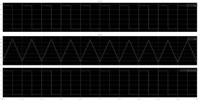
Fig. 2.6, Scope results of 2-Quadrant DC Chopper.
- We can observe that the voltage waveform doesn’t go below zero. Thus, the value of voltage always stays positive and the minimum value is zero.
- However, the current increases ad decreases between positive and negative values.
- As the pulse width amplitude is 10 and minimum is zero, the gate pulses remain 10 during ON states and 0 during OFF states.
Brushless DC (BLDC) Electric Motor:
- A brushless DC electric motor is a synchronous motor using a direct current (DC) electric power supply. It uses an electronic closed loop controller to switch DC currents to the motor windings, producing magnetic fields which effectively rotate in space and which the permanent magnet rotor follows. The controller adjusts the phase and amplitude of the DC current pulses to control the speed and torque of the motor. This control system is an alternative to the mechanical commutator(brushes) used in many conventional electric motors.
- In brushed motors this is done with a rotary switch on the motor’s shaft called a commutator. It consists of a rotating cylinder divided into multiple metal contact segments on the rotor. The segments are connected to conductor windings on the rotor. Two or more stationary contacts called brushes, made of a soft conductor like graphite, press against the commutator, making sliding electrical contact with successive segments as the rotor turns. The brushes selectively provide electric current to the windings. As the rotor rotates, the commutator selects different windings and the directional current is applied to a given winding such that rotor’s magnetic field remains misaligned with the stator and creates a torque in one direction.
- The commutator has certain disadvantages that led to a decline in use of brushed motors.
- The friction of the brushes sliding along the rotating commutator segments causes power losses that can be significant in a low power motor.
- The soft brush material wears down due to friction, creating dust, and eventually the brushes must be replaced. This makes commutated motors unsuitable for low particulate or sealed applications like hard disk motors, and for applications that require maintenance-free operation.
- The electrical resistance of the sliding brush contact causes a voltage drop in the motor circuit called brush drop which consumes energy.
- The repeated abrupt switching of the current through the inductance of the windings causes sparks at the commutator contacts, which is a fire hazard in explosive atmospheres and a source of electronic noise, which can cause electromagnetic interference in nearby microelectronic circuits.
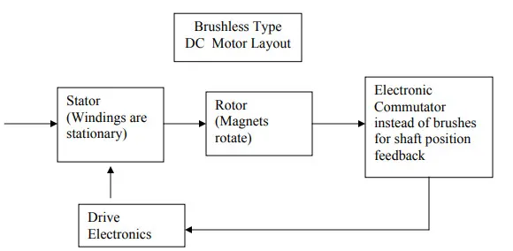
Fig. 3.1, Bock diagram of BLDC Motor.
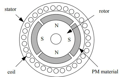
Fig. 3.2, Cross-section of a BLDC motor.
Stator:
The structure of the stator of a BLDC Motor is similar to that of an induction motor. It is made up of stacked steel laminations with axially cut slots for winding. The windings in BLDC are slightly different than that of the traditional induction motor.
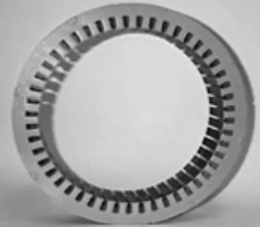
Fig. 3.3, Stator of BLDC motor.
Generally, most BLDC motors consists of three stator windings that are connected in star or ‘Y’ fashion (without a neutral point). Additionally, based on the coil interconnections, the stator windings are further divided into Trapezoidal and Sinusoidal Motors.
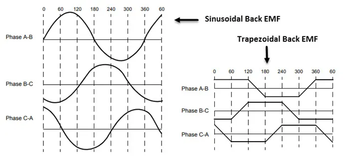
Fig. 3.4, Waveforms of BLDC motor output showing back EMF
In a trapezoidal motor, both the drive current and the back EMF are in the shape of a trapezoid (sinusoidal shape in case of sinusoidal motors). Usually, 48 V (or less) rated motors are used in automotive and robotics (hybrid cars and robotic arms).
Rotor:
The rotor part of the BLDC Motor is made up of permanent magnets (usually, rare earth alloy magnets like Neodymium (Nd), Samarium Cobalt (SmCo) and alloy of Neodymium, Ferrite and Boron (NdFeB)).
Based on the application, the number of poles can vary between two and eight with North (N) and South (S) poles placed alternately. The following image shows three different arrangements of the poles. In the first case, the magnets are placed on the outer periphery of the rotor.
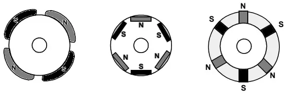
Fig. 3.5, Arrangement of poles in BLDC motor
The second configuration is called magnetic-embedded rotor, where rectangular permanent magnets are embedded into the core of the rotor. In the third case, the magnets are inserted into the iron core of the rotor.
Position Sensors (Hall Sensors):
Since there are no brushes in a BLDC Motor, the commutation is controlled electronically. In order to rotate the motor, the windings of the stator must be energized in a sequence and the position of the rotor (i.e., the North and South poles of the rotor) must be known to precisely energize a particular set of stator windings.
A Position Sensor, which is usually a Hall Sensor (that works on the principle of Hall Effect) is generally used to detect the position of the rotor and transform it into an electrical signal. Most BLDC Motors use three Hall Sensors that are embedded into the stator to sense the rotor’s position.
The output of the Hall Sensor will be either HIGH or LOW depending on whether the North or South pole of the rotor passes near it. By combining the results from the three sensors, the exact sequence of energizing can be determined.
Operation of BLDC Motor:
- The underlying principles for the working of a BLDC motor are the same as for a brushed DC motor; i.e., internal shaft position feedback. In case of a brushed DC motor, feedback is implemented using a mechanical commutator and brushes. With a in BLDC motor, it is achieved using multiple feedback sensors. The most commonly used sensors are hall sensors and optical encoders. Hall sensors work on the hall-effect principle that when a current-carrying conductor is exposed to the magnetic field, charge carriers experience a force based on the voltage developed across the two sides of the conductor.
- If the direction of the magnetic field is reversed, the voltage developed will reverse as well. For Hall-effect sensors used in BLDC motors, whenever rotor magnetic poles (N or S) pass near the hall sensor, they generate a HIGH or LOW level signal, which can be used to determine the position of the shaft.
- In a commutation system – one that is based on the position of the motor identified using feedback sensors – two of the three electrical windings are energized at a time as shown in figure 3.6.
- In figure 4 (A), the GREEN winding labelled “001” is energized as the NORTH pole and the BLUE winding labelled as “010” is energized as the SOUTH pole. Because of this excitation, the SOUTH pole of the rotor aligns with the GREEN winding and the NORTH pole aligns with the RED winding labelled “100”. In order to move the rotor, the “RED” and “BLUE” windings are energized in the direction shown in figure 4(B). This causes the RED winding to become the NORTH pole and the BLUE winding to become the SOUTH pole. This shifting of the magnetic field in the stator produces torque because of the development of repulsion (Red winding – NORTH-NORTH alignment) and attraction forces (BLUE winding – NORTH-SOUTH alignment), which moves the rotor in the clockwise direction. In figure 4 (A), the GREEN winding labelled “001” is energized as the NORTH pole and the BLUE winding labelled as “010” is energized as the SOUTH pole. Because of this excitation, the SOUTH pole of the rotor aligns with the GREEN winding and the NORTH pole aligns with the RED winding labelled “100”. In order to move the rotor, the “RED” and “BLUE” windings are energized in the direction shown in figure 4(B). This causes the RED winding to become the NORTH pole and the BLUE winding to become the SOUTH pole. This shifting of the magnetic field in the stator produces torque because of the development of repulsion (Red winding – NORTH-NORTH alignment) and attraction forces (BLUE winding – NORTH-SOUTH alignment), which moves the rotor in the clockwise direction.
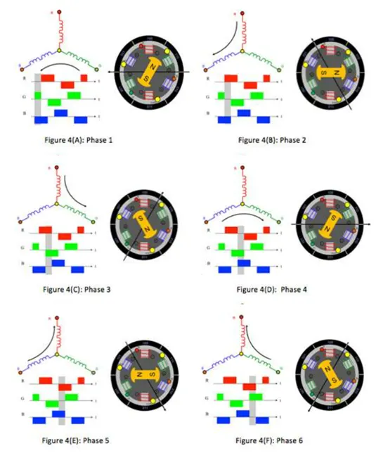
Fig. 3.6, Commutation Process in a motor.
- This torque is at its maximum when the rotor starts to move, but it reduces as the two fields align to each other. Thus, to preserve the torque or to build up the rotation, the magnetic field generated by stator should keep switching. To catch up with the field generated by the stator, the rotor will keep rotating. Since the magnetic field of the stator and rotor both rotate at the same frequency, they come under the category of synchronous motor.
- This switching of the stator to build up the rotation is known as commutation. For 3-phase windings, there are 6 steps in the commutation; i.e., 6 unique combinations in which motor windings will be energized.
Advantages of BLDC Motors:
Since BLDC Motors are electronically commutated, there are several advantages over traditional Brushed DC Motors. Some of them are:
- No wear and tear (due to absence of brushes)
- High efficiency
- Better speed vs torque characteristics
- Long life
- Less noise or noiseless operation
- Significantly higher RPM
Applications of Brushless DC Motors:
Some of the areas of applications of BLDC Motors are mentioned below:
- Single speed applications
- Adjustable speed applications
- Position control
- Low noise applications
- High speed applications
REFERENCES:
- Basics of Brushless DC Motors (BLDC Motors) | Construction, Working (electronicshub.org)
- Insulated-gate bipolar transistor - Wikipedia
- Power MOSFET - Wikipedia
- Bipolar junction transistor - Wikipedia
- Implement four-quadrant chopper DC drive - Simulink (mathworks.com)
- DC7 - Four-Quadrant Chopper 200 HP DC Drive - MATLAB & Simulink (mathworks.com)
- Multi Quadrant Operation of DC Motor in Simulink : Skill-Lync