Week-7 Challenge: DC Motor Control
1. A. Explain a MATLAB demo model named ‘Speed control of a DC motor using BJT H-bridge’.
B. Comment on the armature current shoot-up from the scope results.
C. Refer to the help section of ‘The Four-Quadrant Chopper DC Drive (DC7) block’. Compare it with the H-bridge model.
A. This example shows Simulation of an H-bridge which is used to generate a chopped voltage and to control the speed of a DC motor.Chopper is nothing but the dc dc converter.It ay step up or down the input voltage.We have different toplogies for the same.The chopper can be made to operate in the various quadrants of the torque speed characteristics.They may be Class A chopper,two quadrant chopper, Class E chopper etc.Here in this simulation the Bipolar Junction Transistor (BJT) has three terminal and is used for power switching purpose,here the BJT acts as a switch ON and OFF .When it is ON it operates in saturation region and when it is OFF it works in the cut off region. The ON and OFF is controlled by the Base Current.The basic diagram of the four quadrant chopper is given below.
When a we plot the Torque speed characteristics, the motor can operate in the four quadrants of the graph as shown in the below figure.
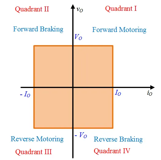
Here the voltage is proportional to speed and current is proportional to torque.
This the figure of the Simulink Model of the Speed Control DC Motor BJT H-Bridge.
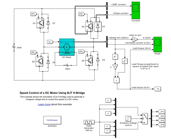
The H-bridge consists of four BJT/Diode pairs. Two transistors are switched simultaneously: Q1 and Q4 or Q2 and Q3. When Q1 and Q4 are fired, a positive voltage is applied to the motor and diodes D2-D3 operate as free-wheeling diodes when Q1 and Q4 are switched off. When Q2 and Q3 are fired, a negative voltage is applied to the motor and diodes D1-D4 operate as free-wheeling diodes when Q2 and Q3 are switched off.When Switching the switches of the same leg are not turned ON beacuse it leads to short circuit of voltage source and the load.
B.Comment on the armature current shoot-up from the scope results.
During the starting the back emf will be zero therefore the speed will also be zero,therefore the motor draws large amount of current.Now with duty cycle of 75% the armature current,torque and the speed waveform are given below.The shoot in the armature current is due to the absence of back emf so current increases to high value during the starting.
I = V-Eb/Ra
Eb =0 during starting.
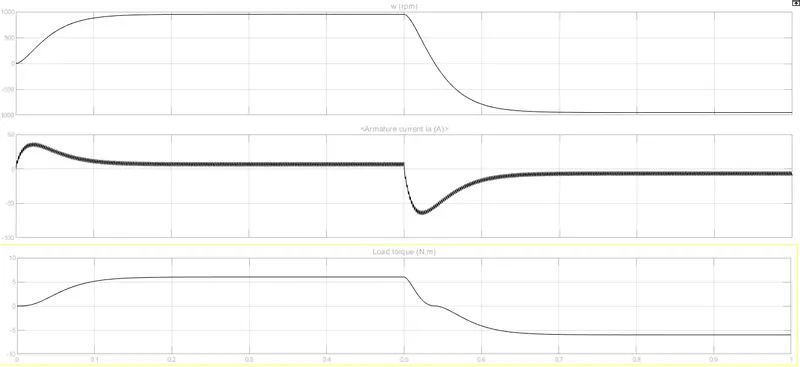
Now the duty cycle is changed to 50%.When the pulse width amplituse decreases the voltage applied across the dc motor also decreases and the current decreases as shown in the below figure.
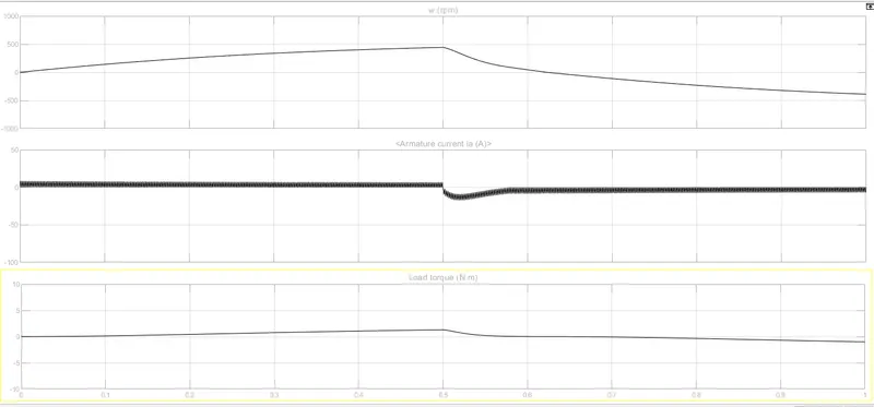
C. Refer to the help section of ‘The Four-Quadrant Chopper DC Drive (DC7) block’. Compare it with the H-bridge model.
It is four quadrant operation of dc motor which is supplied by the chopper.The drive has been implemented with the closed loop.The armature voltage is provided by converter which is employed by IGBTcontrolled by by two PI Regulators.It has got two regulators
1. speed regulator
2. current regulator
The speed regulator outputs the armature current reference used by the current controller inoder to obtain the desired electromagnetic torque.
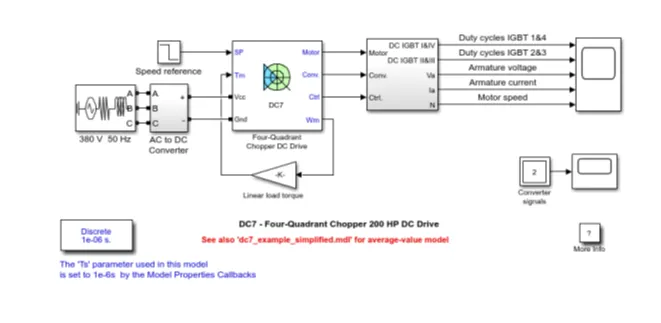
Comparision with H Bridge:
- The stability of the voltage and current is higher in four quadrant chopper than with BJT H bridge as the four quadrant uses the step by step ramping strategy for change in motor direction.
- Regenerative braking is here it is possible but in BJT is is not possible.
- This four quadrant is widely used in Industries to control the speed of the dc motor,BJT controlled is used in small or robotics applications.
- The current values are continous in BJT where aa in four quadrant it is chopped.
- Four quadrant provides better efficiency and operates at high power and BJT operate at moderate power level.
2.Develop a 2-quadrant chopper using simulink & explain the working of the same with the relevant results.
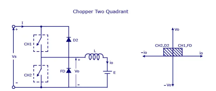
Two quadrant chopper is obtained by connecting type Class A and Class B choppers in parallel.Here two power semiconductor switches are used with parallel diodes which is used for free wheeling of the energy.Let us assume that the switch is ON for DT period and it is OFF for (1-D)T period. The CH1 will be turned on during the DT period and the CH2 will be turned on for (1-D)T period. Together inductance L and Voltage source E (back emf) form the dc motor. The Chopper operates in forward motoring mode in quadrant 1 where CH1 & FD will conduct.In quadrant 2 it operates in the forward braking mode where CH2 and the D2 will be conducting.
Below is the mathematical model of the 2 quadrant chopper feeding the dc motor.The power semiconductor switches used are IGBT with parallel diodes.The current and voltage measurement block are used to measure the current and voltage respectively from source and the load side.Pulse Generator is used to generate pulses to the power switches.
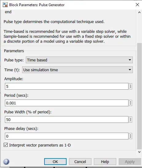
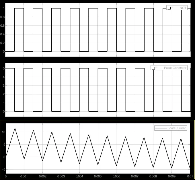
Pulse generator Configuration: Amplitude is taken as 5 Volts, with a duty cycle of 50% for a period of 0.001sec.
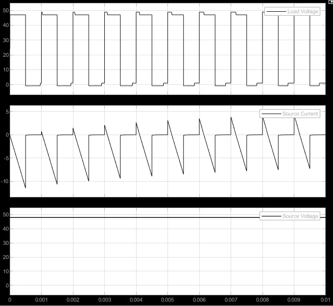
Upper switch Gate is directly connected to the pulse generator and lower switch gate is connected to the NOT gate.Input voltage given is 48V.Together inductance L and Voltage source E (back emf) form the dc motor.
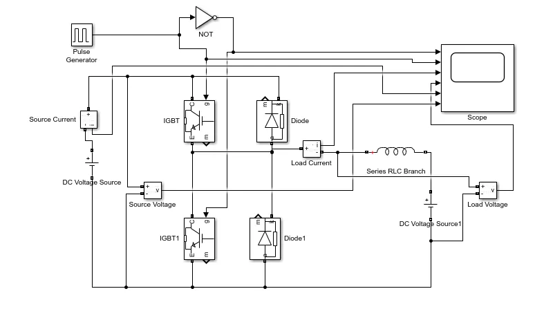
Below are the screen shots of the waveforms pertaining to the above model,we have taken the six output waveforms that is source and load current, source and load voltage and the pulse generator output waveforms. These output waveforms match the therotical waveforms. For the respective waveforms legend is enabled.
3. Explain in a brief about operation of BLDC motor.
Construction:
- BLDC motors have many similarities to Induction motors and brushed DC motors in terms of construction and working principle.
- BLDC motors also have a stator and a PM rotor.
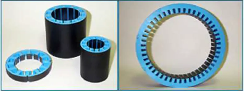
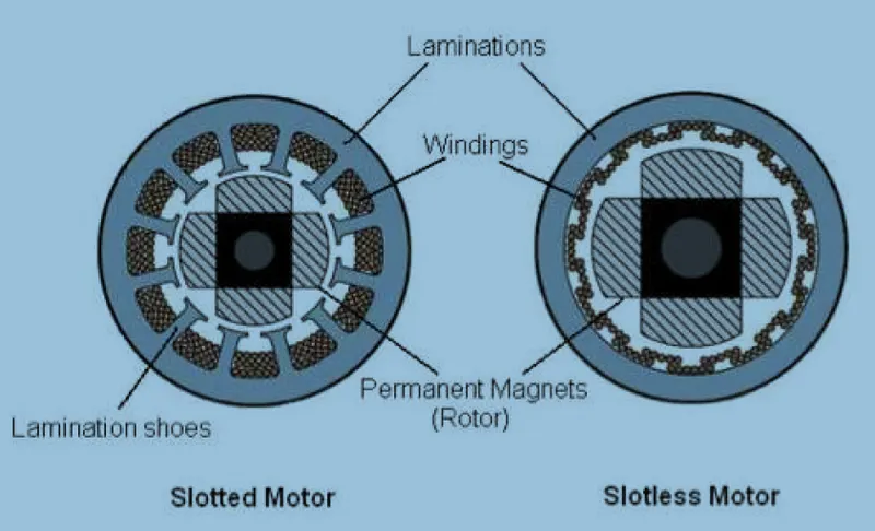
- Stator:Stator is made out of laminated steel and Windings in a stator can be arranged in two patterns; i.e. a star pattern (Y) or delta pattern (Δ).Steel laminations in the stator can be slotted or slot less.A slot-less core has lower inductance, thus it can run at very high speeds.Because of the absence of teeth in the lamination stack, requirements for the cogging torque also go down.The main disadvantage of a slot-less core is higher cost because it requires more winding to compensate for the larger air gap.Proper selection of the laminated steel and windings for the construction of stator are crucial to motor performance.Below figure is the Laminated steel stampings- Stator
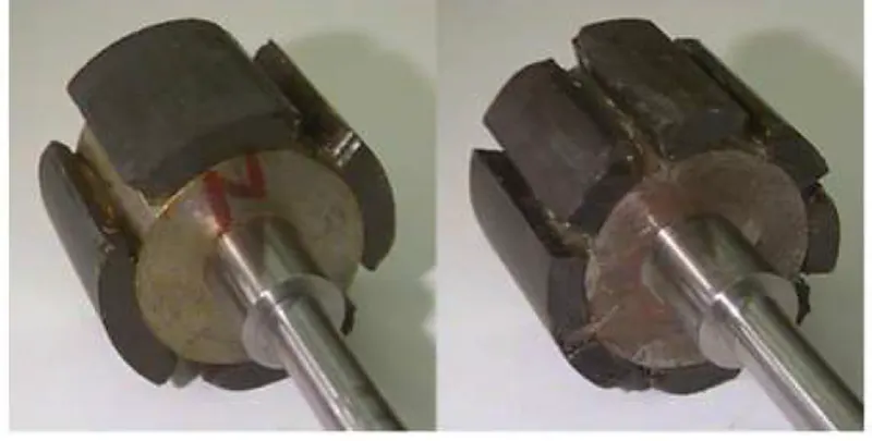
- Rotor: The rotor of a typical BLDC motor is made out of permanent magnets.Depending upon the application requirements, the number of poles in the rotor may vary.Increasing the number of poles does give better torque but at the cost of reducing the maximum possible speed.Another rotor parameter that impacts the maximum torque is the material used for the construction of permanent magnet, the higher the flux density of the material, the higher the torque.Below figure is the Permanent magnet Rotor.
Working Principle:
- The underlying principles for the working of a BLDC motor are the same as for a brushed DC motor i.e., “internal shaft position feedback”.
- In case of a brushed DC motor, feedback is implemented using a mechanical commutator and brushes.
- With a in BLDC motor, it is achieved using multiple feedback sensors(Hall Effect Sensors).
- Hall sensors work on the hall-effect principle. that “when a current-carrying conductor is exposed to the magnetic field, charge carriers experience a force based on the voltage developed across the two sides of the conductor”.
- If the direction of the magnetic field is reversed, the voltage developed will reverse as well. For Hall effect sensors used in BLDC motors, whenever rotor magnetic poles (N or S) pass near the hall sensor, they generate a HIGH or LOW level signal, which can be used to determine the position of the shaft.
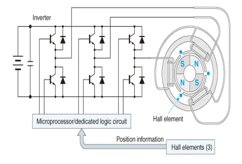
- Based on the position of the motor identified using feedback sensors, two of the three electrical windings are energized at a time as shown in figure.