DC Motor Control
1.
BJT-H Bridge:
The Bipolar Junction Transistor (BJT) when used for power switching applications, operates as an IGBT. When it is conducting (BJT operating in the saturated region), a forward voltage Vf is developed between collector and emitter (in the range of 1 V). Therefore, the IGBT block can be used to model the BJT device.
The IGBT block does not simulate the gate current controlling the BJT or IGBT. The switch is controlled by a Simulink® signal (1/0). The DC motor uses the pre-set model (5 HP 24V 1750 rpm). It simulates a fan type load (where Load torque is proportional to square of speed). The armatures mean voltage can be varied from 0 to 240 V when the duty cycle (specified in the Pulse Generator block) is varied from 0 to 100%.
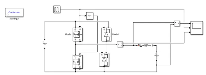
The H-bridge consists of four BJT/Diode pairs (BJT simulated by IGBT models). Two transistors are switched simultaneously: Q1 and Q4 or Q2 and Q3. When Q1 and Q4 are fired, a positive voltage is applied to the motor and diodes D2-D3 operate as free-wheeling diodes when Q1 and Q4 are switched off. When Q2 and Q3 are fired, a negative voltage is applied to the motor and diodes D1-D4 operate as free-wheeling diodes when Q2 and Q3 are switched off.
Chopper:
A DC chopper is also known as DC- DC converter. It is a static device which is used to obtain a variable DC voltage from a constant DC Voltage source. A DC-to-DC converter is an electronic circuit or electromechanical device that converts a source of direct current (DC) from one voltage level to another. It is a type of electric power converter. Power levels range from very low (small batteries) to very high (high-voltage power transmission). Choppers are of two types- Step Down chopper and Step Up choppers.
Process:
- Explain and Run MATLAB demo ‘Speed control of a DC motor using BJT-H Bridge’. The armature current shoot-up from the scope results are to be observed.
- Open the MATLAB and In the Help documentation type Speed Control of a DC motor using BJT –H Bridge
- Results tab opens, and then select the model and click Open Model.
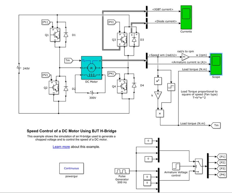
- The model is opened in a Simulink workspace.
- Run the model as it is and observe the graphs of the armature current.
- Now, at the bottom part of the model, there’s a Pulse generator block, click on it and run the model.
- Check the outputs. Follow the same for 75% and 50% just to check if the armature voltage is decreased sharply after half of the simulation time.
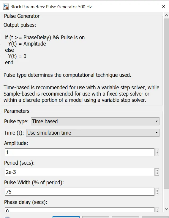
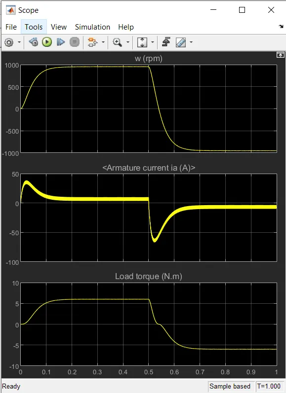
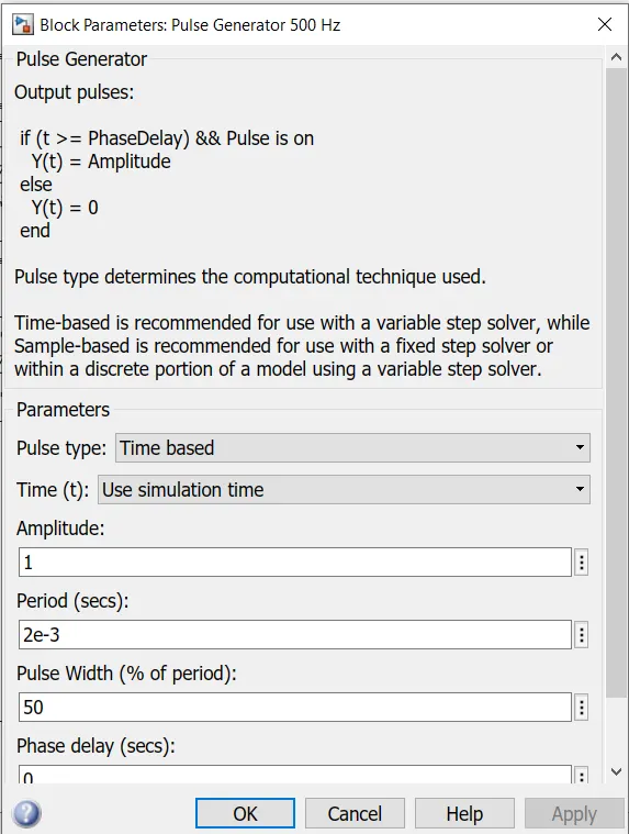
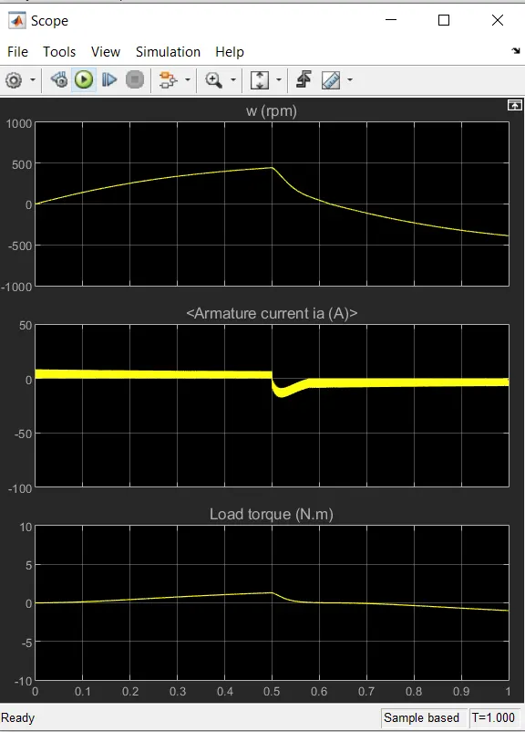
- As pulse width decreases the steap value of the armature current decreases.
2.
Four Quadrant Chopper DC Drive Block:
The 200 HP DC motor is separately excited with a constant 150 V DC field voltage source. The armature voltage is provided by an IGBT converter controlled by two PI regulators. The converter is fed by a 515 V DC bus obtained by rectification of a 380 V AC 50 Hz voltage source. In order to limit the DC bus voltage during dynamic braking mode, a braking chopper has been added between the diode rectifier and the DC7 block.
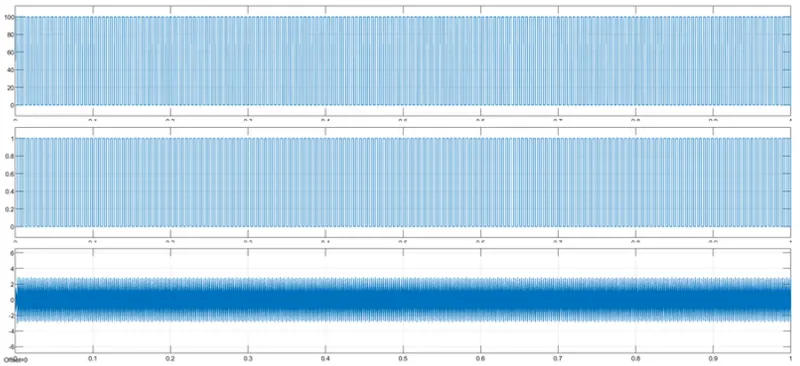
The first regulator is a speed regulator, followed by a current regulator. The speed regulator outputs the armature current reference (in p.u.) used by the current controller in order to obtain the electromagnetic torque needed to reach the desired speed. The speed reference change rate follows acceleration and deceleration ramps in order to avoid sudden reference changes that could cause armature over-current and destabilize the system. The current regulator controls the armature current by computing the appropriate duty ratios of the 5 kHz pulses of the four IGBT devices (Pulse Width Modulation). For proper system behaviour, the instantaneous pulse values of IGBT devices 1 and 4 are opposite to those of IGBT devices 2 and 3. This generates the average armature voltage needed to obtain the desired armature current. In order to limit the amplitude of the current oscillations, a smoothing inductance is placed in series with the armature circuit.
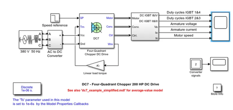
- The Stability of the voltage and current supply is higher in the four quadrant compared to BJT as the four quadrant uses the step by step ramping strategy for the change in the motor direction whereas the stability is lost.
- Regenerative braking is possible in four quadrant but not in BJT.
- It is widely used in automobile sector to control DC motor speed and direction in Four quadrant. Whereas the BJT is used in robotics and electro-mechanical devices to control DC motor speed and direction.
- The current values are continuous in BJT and In Four Quadrants; it is chopped so that the simulation takes less time.
- To change the direction of the motor, current signals are interrupted in four quadrants. Whereas in BJT the polarity of the current needs to be changed.
- The main advantage of Four quadrant is that it operates in all the four quadrants but BJT can movie only is two directions.
- Four Quadrants provides better efficiency and operates at high power levels when compared to BJT that operates at moderate power levels.
3.
Two Quadrant Chopper DC Drive Block:
The Two-Quadrant Chopper DC Drive (DC6) block represents a two-quadrant, DC-supplied, chopper (or DC-DC PWM converter) drive for DC motors. This drive features closed-loop speed control with two-quadrant operation. The speed control loop outputs the reference armature current of the machine. Using a PI current controller, the chopper duty cycle corresponding to the commanded armature current is derived. This duty cycle is then compared with a sawtooth carrier signal to obtain the required PWM signals for the chopper.
The main advantages of this drive, compared with other DC drives, are its implementation simplicity and that it can operate in two quadrants (forward motoring and reverse regeneration). In addition, due to the use of high switching frequency DC-DC converters, a lower armature current ripple (compared with thyristor-based DC drives) is obtained. However, for all two-quadrant DC drives, reversible and regenerative operations (reverse motoring and forward regeneration), which are required in most DC drives, cannot be obtained.
The Two-Quadrant Chopper DC Drive block uses these blocks from the Electric Drives/Fundamental Drive Blocks library:
- Speed Controller (DC)
- Regulation Switch
- Chopper
4.
BLDC Motor:
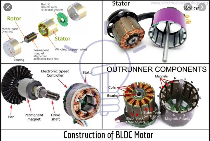
A brushless DC electric motor (BLDC motor or BL motor), also known as an electronically commutated motor (ECM or EC motor) or synchronous DC motor, is a synchronous motor using a direct current (DC) electric power supply. It uses an electronic closed looped controller to switch DC currents to the motor windings producing magnetic fields which effectively rotate in space and which the permanent magnet rotor follows. The controller adjusts the phase and amplitude of the DC current pulses to control the speed and torque of the motor. This control system is an alternative to the mechanical commutators (brushes) used in many conventional electric motors.
The construction of a brushless motor system is typically similar to a permanent magnet synchronous motor (PMSM), but can also be a switched reluctance motor, or an induction (asynchronous) motor. They may also use neodumium magnets and be outrunners (the stator is surrounded by the rotor), inrunners (the rotor is surrounded by the stator), or axial (the rotor and stator are flat and parallel).
The advantages of a brushless motor over brushed motors are high power-to-weight ratio, high speed, nearly instantaneous control of speed (rpm) and torque, high efficiency, and low maintenance. Brushless motors find applications in such places as computer peripherals (disk drives, printers), hand-held power tools, and vehicles ranging from model aircraft to automobiles. In modern washing machines, brushless DC motors have allowed replacement of rubber belts and gearboxes by a direct-drive design.