Week-7 Challenge: DC Motor Control
Most of mini DC motors have two terminals because they are series type (armature and field windings are connected in series) DC motors. Please refer the figure given below.
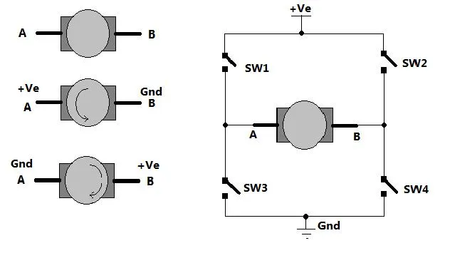
Fig. 1: Image showing H-Bridge circuit used for controlling direction of rotation of a DC Motor
As shown in figure there are two terminals ‘A’ and ‘B’ of DC motor. Now if we connect terminal A with +Ve supply and terminal B with –Ve supply or ground the current will flow from motor from A to B and motor will rotate in one direction – say clockwise (CW) or forward direction. Now as shown in second figure we change the supply terminals. Now B is connected with +Ve and A is connected to ground. The current will flow from motor from B to A and motor will rotate in other direction (counter clockwise – CCW or reverse).
So next question is how to give reversible supply to motor?
The arrangement is shown in right side of figure. Four switches are connected in between +Ve supply and ground and DC motor is connected in between two switches as shown. Such circuit arrangement is known as H-bridge because it looks like letter ‘H’ (H-bridge circuits are most widely used in DC motor drivers). Let us see how it gives reverse supply to motor.
If SW1 and SW4 are pressed simultaneously then current will flow from +Ve – SW1 – A – B – SW4 – Gnd. So motor will rotate in one direction. Open (release) SW1 and SW4 to stop motor. Now if SW2 and SW3 are pressed current will flow from +Ve – SW2 – B – A – SW3 – Gnd. So motor gets reverse supply and it will rotate in another direction.
(Caution: care has to be taken that SW1 and SW3 or SW2 and SW4 must not be pressed simultaneously otherwise it will short circuit the supply)
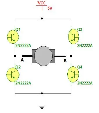
Fig. 2: Circuit Diagram of H-Bridge built by transistor for controlling DC motor speed and rotation
The circuit replaces the switches with NPN type transistors. We all know that transistor works as switch. For NPN transistor if we give +Ve input to base it will turn ON and if we give 0 input it will be turned OFF.
So in this circuit if Q1 and Q4 are turned ON simultaneously the motor will rotate forward and if Q2 and Q3 are turned ON then motor will rotate reverse.
Motor can be rotated forward and reverse using 4 transistors only.
Now let us move to vary the speed of DC motor. The DC motor speed varies as applied input voltage varies. As you increase applied input voltage the speed will increase and vice versa. Applying max rated voltage will rotate motor at full speed (caution: do not apply more than max rated voltage to motor otherwise motor windings may get burnt).
Now the question is how to apply variable voltage to motor?
One of the very popular methods for generating variable DC voltage is pulse width modulation (PWM). It is explained in figure given below.
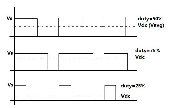
Fig. 3: Graph showing Pulse Width Modulation for controlling speed of DC Motor
Pulse width modulation means varying the width (duty) of pulse. Width means ON time Ton of pulse. The average output voltage (Vdc or Vavg) is given by equation
Vdc = [Ton / (Ton+Toff)] × Vs
It directly depends upon Ton. As shown in above figure if duty is 50% the average output voltage Vdc is exactly the half of Vs. If duty is increased to 75%, Vdc also increases to 3/4th of Vs and if duty is decreased to 25%, Vdc reduces to 1/4th of Vs. Thus as pulse width varies the average output voltage varies. So we have to apply PWM to DC motor to vary its speed.
Simulation
This below simulink model shows the simulation of an H-bridge used to generate a chopped voltage and to control the speed of a DC motor.
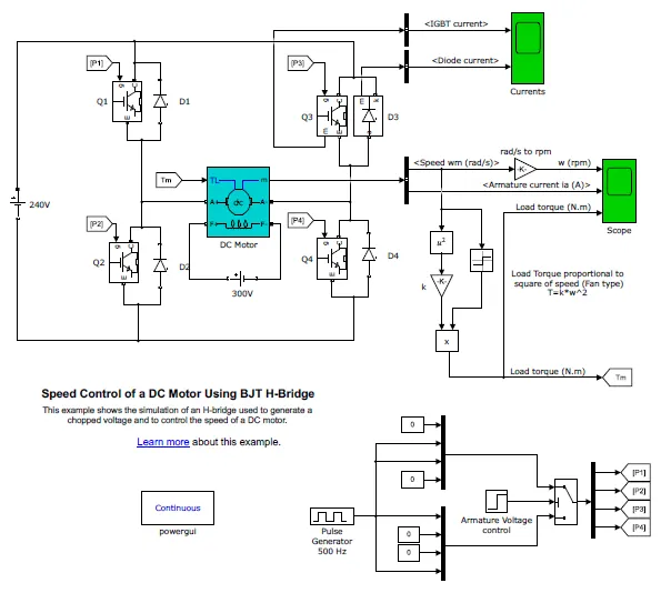
The motor starts in the positive direction with a duty cycle of 75% (mean DC voltage of 180V). At t= 0.5 sec., the armature voltage is suddenly reversed and the motor runs in the negative direction.
'Scope' shows motor speed, armature current and load torque and 'Currents' shows currents flowing in BJT Q3 and diode D3.
After the simmulation is completed the below plot is obtained.
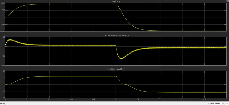
It can be noted that at time 0.5s, rpm and the torque of the motor starts to drop. During this time the armature current drops below -60A. It can be observed that once the torque value starts to drop the armature current shoots. In order to prevent the sudden rise of the armature current the pulse width of the pulse width generator has to be changed. As default the pulse width was set to 75%. We will change it to 45%
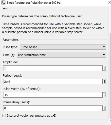
After running the simulation again witht the pulse width modified to 45%. we get below results.
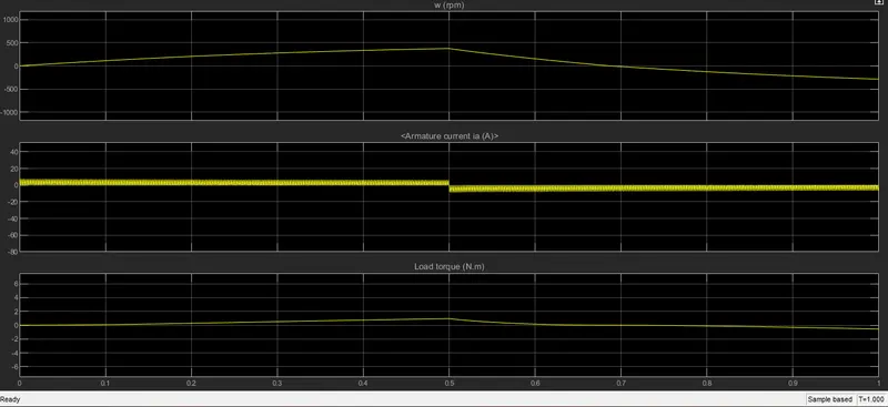
It can be seen that the value of the armature current doesn't shoot up when the direction of the motor is reveresed.
Comparison of four quadrant chopper DC7 block and H bridge model:
- Four-Quadrant Chopper can operates in all four modes (Forward Motoring,Forward Braking, Reverse Motoring andReverse Braking), but H-bridge can operate only in two modes (Forward and Reverse).
- In Four-Quadrant Chopper Regenerative Braking is possible, but H-bridge Regenerative Braking is not possible.
- In Four-Quadrant Chopper Two PI regulator (Speed Regulator and Current Regulator) is used to obtain electromagnetictorque needed to reach the desired speed and control the armature current and stabilize the system, but in H-bridge model PIregulator is not used.
- H-bridge is a electronic circuit that switches the polarity of voltage applied to the load and Four-quadrant Chopper iselectronic switch that is used to interupt one signal under the control of another.
- H-bridge circuit are often used in Robotics and other applications to allow dc motor to run forward and backward.Four-Quadrant Chopper circuit is used to refer numerous type of electronic sitching devices and circuits used in power control andsignal applications.
- Four-Quadrant Chopper model gives better efficiency and high energy(power) storage than H-bridge model.
Develop a 2-quadrant chopper using simulink & explain the working of the same with the relevant results.
In power electronics chopper circuits, unidirectional power semiconductors are used. If these semiconductor devices are arranged appropriately, a chopper can work in any of the four quadrants. we can classify chopper circuits according to their working in any of these four quadrants as type A, type B, type C, type D and type E.
Type -C chopper or Two-quadrant type-A Chopper
Type C chopper is obtained by connecting type –A and type –B choppers in parallel. We will always get a positive output voltage V0 as the freewheeling diode FD is present across the load. When the chopper is on the freewheeling diode starts conducting and the output voltage v0 will be equal to Vs . The direction of the load current i0 will be reversed. The current i0 will be flowing towards the source and it will be positive regardless the chopper is on or the FD conducts. The load current will be negative if the chopper is or the diode D2 conducts. We can say the chopper and FD operate together as type-A chopper in first quadrant. In the second quadrant, the chopper and D2 will operate together as type –B chopper.
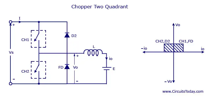
The average voltage will be always positive but the average load current might be positive or negative. The power flow may be life the first quadrant operation ie from source to load or from load to source like the second quadrant operation. The two choppers should not be turned on simultaneously as the combined action my cause a short circuit in supply lines. For regenerative braking and motoring these type of chopper configuration is used.
Type D Chopper or Two-Quadrant Type –B Chopper
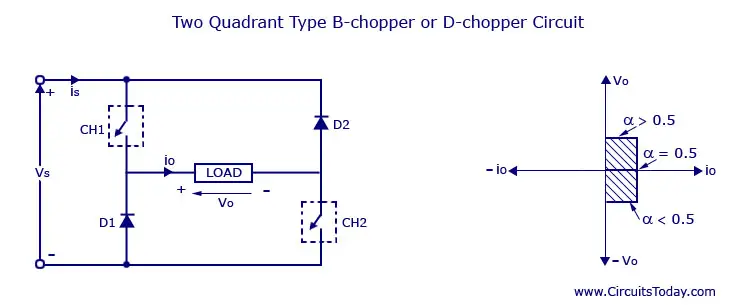
The circuit diagram of the type D chopper is shown in the above figure. When the two choppers are on the output voltage v0 will be equal to Vs . When v0 = – Vs the two choppers will be off but both the diodes D1 and D2 will start conducting. V0 the average output voltage will be positive when the choppers turn-on the time Ton will be more than the turn off time Toff its shown in the wave form below. As the diodes and choppers conduct current only in one direction the direction of load current will be always positive.
The power flows from source to load as the average values of both v0 and i0 is positive. From the wave form it is seen that the average value of V0 is positive thus the forth quadrant operation of type D chopper is obtained.
From the wave forms the Average value of output voltage is given by
V0= (Vs Ton-VsToff)/T = Vs.(Ton-Toff)/T
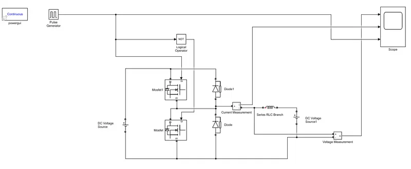
Simulink model of two quadrant chopper
Results:
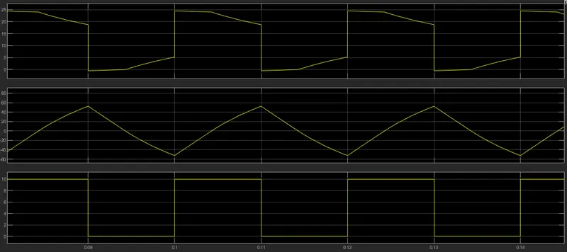
As we can see from the above plot, the voltage doesnt go from positive to negative. The votlage doesnt drop below zero, whereas the current moves from positive to negative. This type of circuit in which the voltage is always positive and current can be either positive or negative is called two quadrant chopper circuit.
Operation of BLDC Motor
BLDC motor works on the principle similar to that of a conventional DC motor, i.e., the Lorentz force law which states that whenever a current carrying conductor placed in a magnetic field it experiences a force. As a consequence of reaction force, the magnet will experience an equal and opposite force. In case BLDC motor, the current carrying conductor is stationary while the permanent magnet moves.
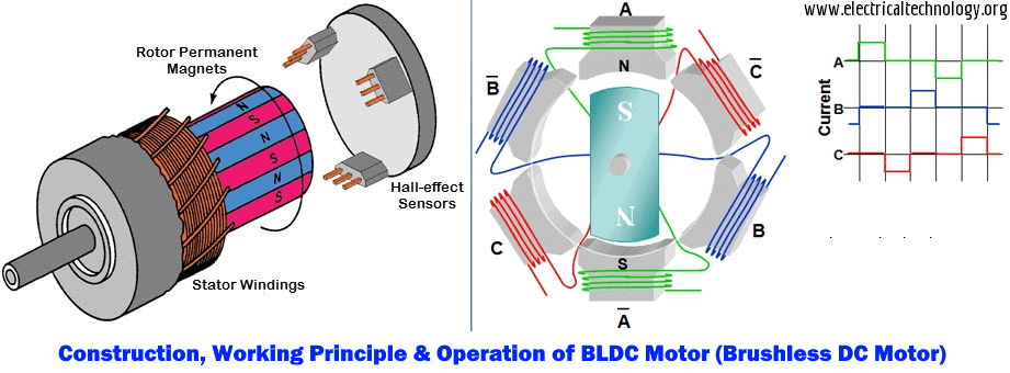
When the stator coils are electrically switched by a supply source, it becomes electromagnet and starts producing the uniform field in the air gap. Though the source of supply is DC, switching makes to generate an AC voltage waveform with trapezoidal shape. Due to the force of interaction between electromagnet stator and permanent magnet rotor, the rotor continues to rotate.
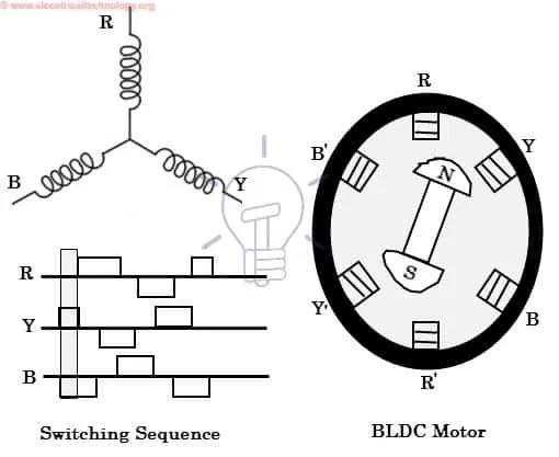
Consider the figure below in which motor stator is excited based on different switching states. With the switching of windings as High and Low signals, corresponding winding energized as North and South poles. The permanent magnet rotor with North and South poles align with stator poles causing motor to rotate.
Observe that motor produces torque because of the development of attraction forces (when North-South or South-North alignment) and repulsion forces (when North-North or South-South alignment). By this way motor moves in a clockwise direction.