Week-6 Challenge: EV Drivetrain
1. Which types of power converter circuits are employed in electric and hybrid electric vehicle?
A power converter is an electrical circuit that changes the electric energy from one form into the desired form optimized for specific load. A converter may do one or more functions and give an output which differs from the input.
Commercial electric vehicles may be broadly classified as:
(1) Battery electric vehicles (BEVs), (2) Hybrid electric vehicles (HEVs), and Fuel cell vehicles (FCVs).
BEVs are purely electric vehicles (EVs), whereas HEVs combine EVs and internal combustion engines (ICEs). FCVs use power from both battery and fuel cell stack
The different configurations of EV power supply show that at least one DC/DC converter is necessary to interface the FC, the Battery or the Super capacitors module to the DC-link.
The main components of an Electric Vehicle are DC-AC inverter, DC-DC converter, battery, and electric motor.
There are two major power electronic units in the general configuration
DC-DC converter
DC-AC inverter
Usually AC motors are used in HEVs or EVs for traction and they are fed by inverter and this inverter is fed by DC-DC converter.
Overview of DC-DC converters (CHOPPER)
DC-DC converters in an electric vehicle may be classified into unidirectional and bidirectional converters. Unidirectional DC-DC converters cater to various onboard loads such as sensors, controls, entertainment, utility, and safety equipments. They are also used in DC motor drives and electric traction. Bidirectional DC-DC converters find applications in places where battery charging, regenerative braking, and backup power are required. The power flow in a bidirectional converter is usually from a low voltage end such as a battery or a supercapacitor to a high voltage side and is referred to as boost operation.
During regenerative braking, the power flows back to the low voltage bus to recharge the battery (buck mode). As a backup power system, the bidirectional DC-DC converter facilitates the safe operation of the vehicle when ICEs or electric drives fail to drive the motor. Due to the aforementioned reasons, high power bidirectional DC-DC converters have gained a lot of importance in the recent past.
The converter topologies are classified as:
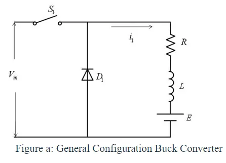
• Buck Converter: In Figure a ,a buck converter is shown .The buck converter is step down converter and produces a lower average output voltage than the dc input voltage.
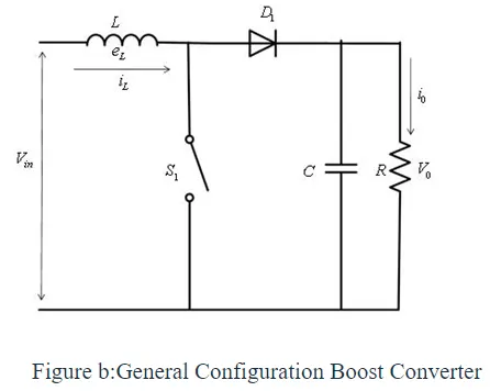
• Boost converter: In Figure b ,a boost converter is shown. The output voltage is always greater than the input voltage.
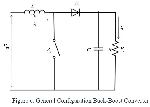
• Buck-Boost converter: In Figure c ,a buck-boost converter is shown. The output voltage can be either higher or lower than the input voltage.
The amount of power flow between the input and the output can be controlled by adjusting the duty cycle (ratio of on/off time of the switch ).Usually, this is done to control the output voltage, the input current, the output current, or to maintain a constant power
Why is a DC/DC converter necessary?
While DC/DC converters can be based on a number of different designs, the underlying function remains the same. We might be talking about a step-up converter, which turns a low-voltage input into a high-voltage output, or a step-down converter, which does the opposite.
In electric vehicles which use a DC motor, running the motor can use up to three times the voltage provided by the battery. With the help of the right converter, we can bridge this gap without having to possibility to a larger, prohibitively heavy battery.
DC-AC converters (Inverters)
An inverter is a device that converts DC power from the battery to AC power used in an electric vehicle motor. The inverter can change the speed at which the motor rotates by adjusting the frequency of the alternating current.
Why DC/AC is necessary?
The use of Inverters can increase or decrease the power or torque of the motor by adjusting the amplitude of the signal.
It plays a significant role in capturing energy from regenerative braking and feeding it back to the battery.
2. What is EV steady state speed if duty cycle is 70%?
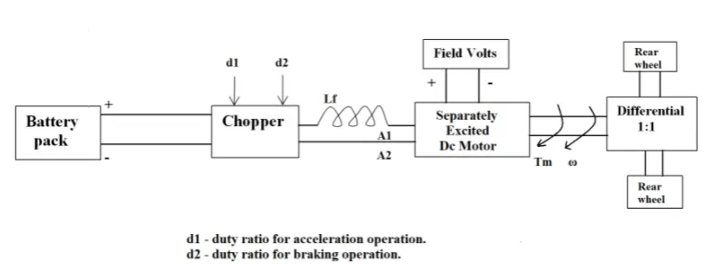
he other parameters of the electric vehicle is given below,
Motor and Controller Parameters:
Rated Armature voltage (V)= 72 V
Rated armature current (Ia)= 400 A
Armature resistance (Ra)= 0.5Ω
KΦ= 0.7 Volt second
Chopper Switching frequency= 400 Hz
Duty Cycle = 70% = 0.7
The vehicle speed-torque characteristics are given by the below equation
`Tv = 24.7+(0.0051*omega^2)` .............. (1)
The voltage at terminal is
`Vt = V * 0.7`
Torque equation for the motor is given by
`T = ((Vt*Kphi)/(Ra))-omega((Kphi)^2/(Ra))`
Subsituting the values we get,
`T = 70.56 - omega*0.98` ..................(2)
Equating equation (1) and (2),
Tv = T
`24.7 + (0.0051*omega^2) = 70.56-omega*0.98`
Solving for omega we get,
`omega =38.9 (rad)/sec`
Matlab script:
clear all
close all
clc

omega = linspace(0,100,2000);

%Given parameters
I = 400;          %armature current in amp
Ra = 0.5;         %armature resistance in ohms
V = 72;           %armature voltage in volts
K_phi = 0.7;      %motor constant in V-s
f = 400;          %chopper switching frequency
d = 0.7;          %duty cycle is 70%
Vt = d*V;

%torque equation for motor is,
%T  = ((Vt*Kphi)/(Ra))-omega((Kphi)^2/Ra)
%Substituting the values we get,
%T = 70.56 - omega*0.98

%The vehicle speed torque characterestics equation is given by,
%Tv = 24.7+(0.0051*omega^2)

%now calculating the values of torque for various values of omega
for i = 0:length(omega);
    T = 70.56-omega*(0.98);
    Tv = 24.7 + (0.0051*omega.^2);
end

plot (omega, T)
hold on
plot (omega, Tv)
xlabel ('speed (rad/s)')
ylabel ('Torque (Nm)')
legend ('motor speed torque characterestics','vehicle speed torque characterestics')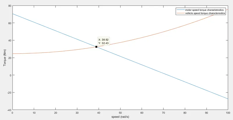
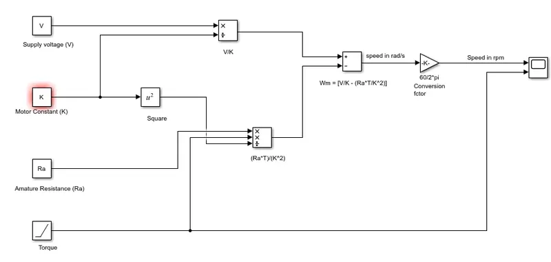
3.Develop a mathematical model of a DC Motor for the below equation using Simulink
`ω = V/(Kϕ) -(Ra)/(Kϕ) ^2 .T`
4. Induction vs DC Brushless motors by Wally Rippel, Tesla.
- The author tells us that there are various kinds of engines and each engine is suitable for a specific requirement. In the same manner there are different kinds of electric motors for different purposes.
- Today the lithium batteries, DC brushless or induction motor and the modulating inverters has replaced the lead acid batteries, DC brush motors and the contactor controllers. There are chances that the latest technology might get changed in future. Both the DC brushless motor and induction motor have their own pros and cons.
- He explains the construction and the working principle of the DC brushless and AC induction motor.
- The Ac induction motor when connected to 3 phase power, the motor has the ability to start under load. There is no need of an inverter.
- The DC motors are more successfull because they are directly compatible with conventional utility power. The DC motor produces no starting torque when connected directly to fixed frequency utility power. They need the aid of an inverter whose “phase” is maintained in step with the angular position of the rotor.
- The author then explains how difficult it is control the AC induction motor when comapred with DC motor.
- DC brushless drives will likely continue to dominate in the hybrid and coming plug-in hybrid markets, and that induction drives will likely maintain dominance for the high-performance pure electrics.
- The hardware for both DC and AC induction motor is common. So in the future we may se AC and DC motor working side by side.