Week-7 Challenge: DC Motor Control
AIM
1. (a) explanation of Matlab demo- ' speed control of DC motor using BJT- H bridge'
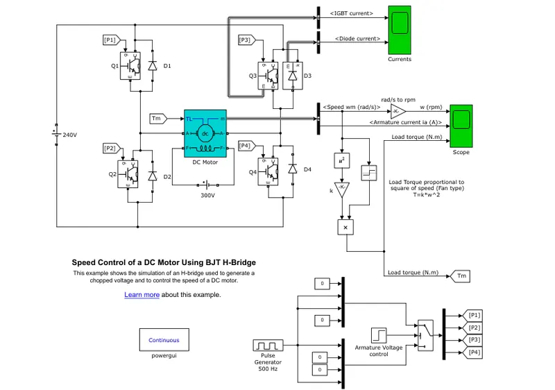
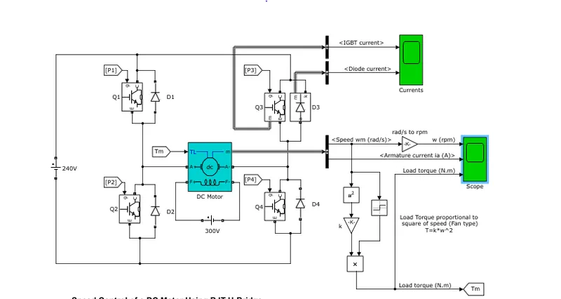
this model represents the DC motor connection arrangement, where the speed of the motor is controlled using BJT, and H-bridge is the layout of the BJT connection
As shown in figure there are two terminals ‘A +’ and ‘A -’ of DC motor. Now if we connect terminal A+ with +Ve supply and terminal A- with –Ve supply or ground the current will flow from motor from A+ to A- and motor will rotate in one direction – say clockwise (CW) or forward direction as we change the supply terminals. Now A- is connected with +Ve and A+ is connected to ground. The current will flow from motor from A- to A+ and motor will rotate in other direction (counter clockwise – CCW or reverse).
The Bipolar Junction Transistor (BJT) when used for power switching applications, operates as an IGBT. When it is conducting (BJT operating in the saturated region), a forward voltage Vf is developed between collector and emitter (in the range of 1 V). Therefore, the IGBT block can be used to model the BJT device.
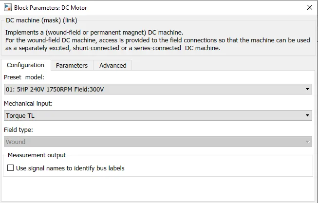
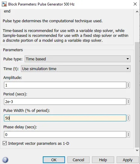
The IGBT block does not simulate the gate current controlling the BJT or IGBT. The switch is controlled by a Simulink signal (1/0). The DC motor uses the preset model (5 HP 24V 1750 rpm). It simulates a fan type load (where Load torque is proportional to square of speed). The armature mean voltage can be varied from 0 to 240 V when the duty cycle (specified in the Pulse Generator block) is varied from 0 to 100%.
The H-bridge consists of four BJT/Diode pairs (BJT simulated by IGBT models). Two transistors are switched simultaneously: Q1 and Q4 or Q2 and Q3. When Q1 and Q4 are fired, a positive voltage is applied to the motor and diodes D2-D3 operate as free-wheeling diodes when Q1 and Q4 are switched off. When Q2 and Q3 are fired, a negative voltage is applied to the motor and diodes D1-D4 operate as free-wheeling diodes when Q2 and Q3 are switched off.
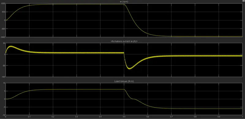
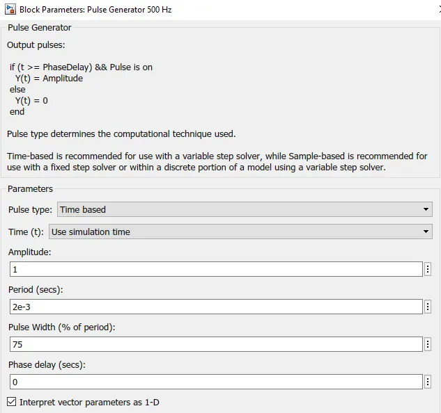
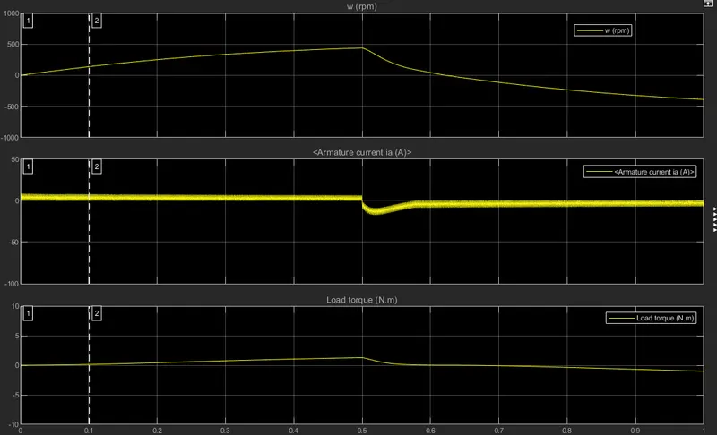
The motor starts in the positive direction with a duty cycle of 75% (mean DC voltage of 180V). At t= 0.5 sec., the armature voltage is suddenly reversed and the motor runs in the negative direction.
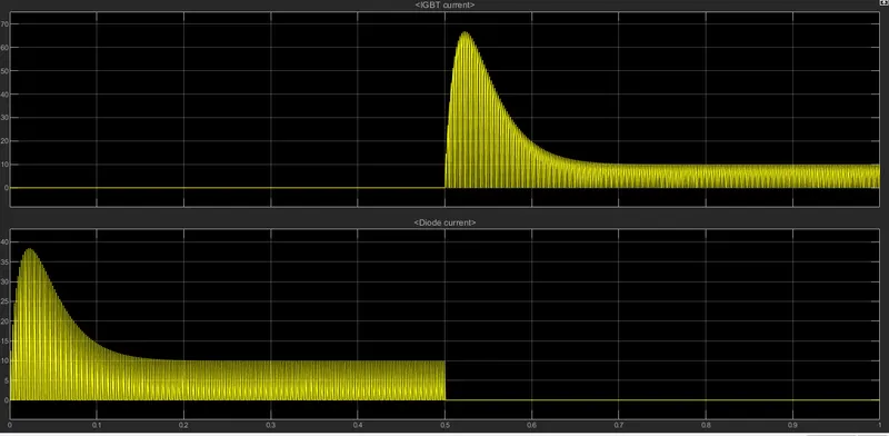
'Scope' shows motor speed, armature current and load torque and 'Currents' shows currents flowing in BJT Q3 and diode D3.
(b). comment on the armature current shoot-up from the scope results
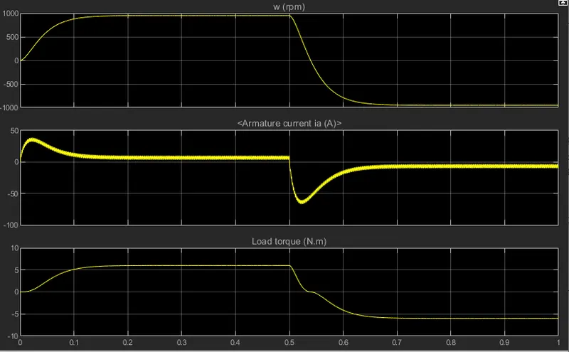
the current drawn by the armature is been represented in the graph, it shoots ups at the start and return backs to normal state rapidly, it rises upto 40 amps and falls down to 7amps after 10 seconds again this happens when the direction of the current is reversed which causes the current to flow in the negative direction,
this sudden shoot up of the current is due to the duty cycle, initially it starts with 75% duty cycle, to stabilize the armature current shootup its needed to regukate the duty cycle when the duty cycle is reduced to 50% theres a decrease in the shootup,
(c). compare the H-bridge model with four quadrant chopper DC drive
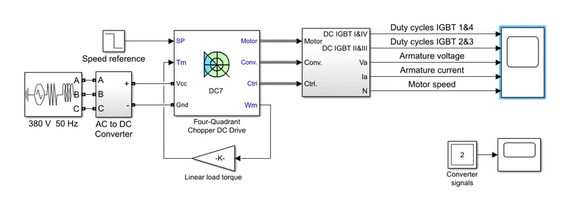
four quadrant chopper DC drive
The Four-Quadrant Chopper DC Drive (DC7) block represents a four-quadrant, DC-supplied, chopper (or DC-DC PWM converter) drive for DC motors. This drive features closed-loop speed control with four-quadrant operation. The speed control loop outputs the reference armature current of the machine. Using a PI current controller, the chopper duty cycle corresponding to the commanded armature current is derived. This duty cycle is then compared with a sawtooth carrier signal to obtain the required PWM signals for the chopper.
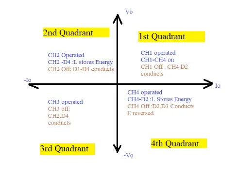
The main advantage of this drive, compared with other DC drives, is that it can operate in all four quadrants (forward motoring, reverse regeneration, reverse motoring, and forward regeneration). In addition, due to the use of high switching frequency DC-DC converters, a lower armature current ripple (compared with thyristor-based DC drives) is obtained. However, four switching devices are required, which increases the complexity of the drive system.
H- bridge model
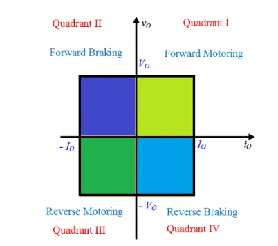
. in four quadrant chopper circuit the current flow is possible in the all four quadrants and it can operate in all four quadrants (forward motoring, reverse regeneration, reverse motoring, and forward regeneration), whereas in h-bridge cirucit the current flow to armature is only possible in 2 directions ie in positive and negative and from which forward and reverse motoring can be made possible
. in four qaudrant chopper circuit four switching devices are required as to perfrorm four operation which increases the complexity of the drive system, where in h-bridge also requires four switching devices but its less complicated and easy to operate and control when compared with four quadrant chopper
. regeneration is not possible in h-bridge circuits, which makes it less preferable to automobile manufactures
. The H-bridge arrangement is generally used to reverse the polarity/direction of the motor, but can also be used to 'brake' the motor, where the motor comes to a sudden stop, as the motor's terminals are shorted, or to let the motor 'free run' to a stop, as the motor is effectively disconnected from the circuit, as this energy can be recovered using regeneration with the help of four quadrant dc circuits where regenration is possible
. H-bridge circuits are more preferable in the inverter cicuits, where the 4quadrants control circuits are preferable in motor controls
2. explain the working of a 2 quadrant chopper
A DC to DC converter is known as chopper, its a static device used to obtain variable dc voltage from a constant dc voltage source, its also used as voltage regulators,
The Two-Quadrant Chopper represents a two-quadrant, DC-supplied, chopper (or DC-DC PWM converter) drive for DC motors, This drive features closed-loop speed control with two-quadrant operation. The speed control loop outputs the reference armature current of the machine. Using a PI current controller, the chopper duty cycle corresponding to the commanded armature current is derived. This duty cycle is then compared with a sawtooth carrier signal to obtain the required PWM signals for the chopper.
The main advantages of this drive, compared with other DC drives, are its implementation simplicity and that it can operate in two quadrants (forward motoring and reverse regeneration). In addition, due to the use of high switching frequency DC-DC converters, a lower armature current ripple (compared with thyristor-based DC drives) is obtained. However, for all two-quadrant DC drives, reversible and regenerative operations (reverse motoring and forward regeneration), which are required in most DC drives, cannot be obtained.
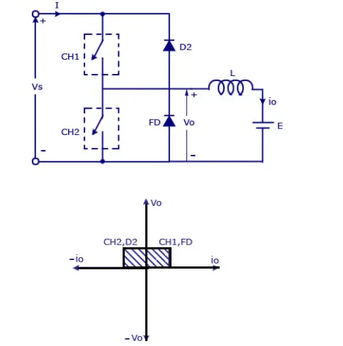
in a two quadrant chopper, the average voltage will be always positive, but the average load current might be positive or negative, the two switches CH1 and CH2 should not be switched together which can result in a short circuit to the system.
A positive voltage is always obtained as the freewheeling diode FD is present across the load, when the chopper CH1 is on the current flows from the source to load, the inductor stores energy. when CH1 is turned off, the freewheeling diode starts conducting the output voltage where Vowill be equal to Vs, the direction of the load current i0 will be reversed, the current Io will be flowing towards teh source, the load current will be negative when the CH2 is turned on , the current completes it path through diode D2.
3. explain in brief about BLDC motor opertaion
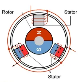
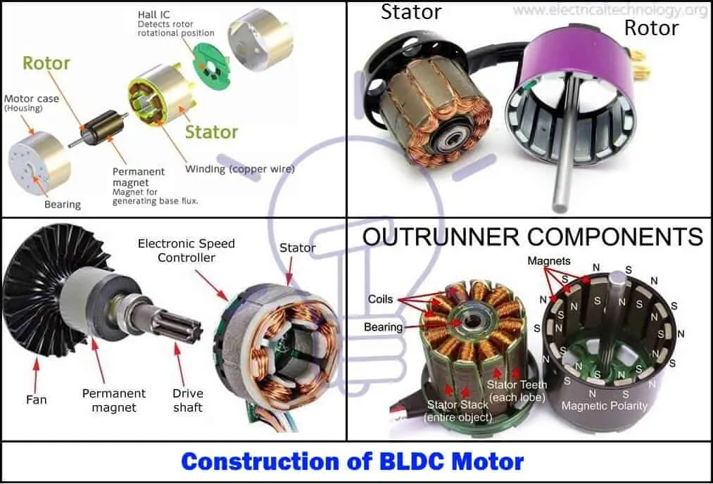
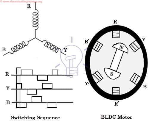
BLDC motor brushless DC motor, its a permanent magnet synchronus motor that operates in DC current which does not have mechancial brushes or commutators or slip rings to transmit DC current to the armature like found in typical DC motors, but is electronically commutated,
Brushless DC motor has only two basic parts: rotor and the stator. The rotor is the rotating part and has rotor magnets whereas stator is the stationary part and contains stator windings. In BLDC permanent magnets are attached in the rotor and move the electromagnets to the stator.
commutator on the rotor form an electric path between a DC electric source and rotor armature windings, BLDC motor employs electrical commutation with permanent magnet rotor and a stator with a sequence of coils. In this motor, permanent magnet (or field poles) rotates and current carrying conductors are fixed.
BLDC motor works on the principle similar to that of a conventional DC motor, the Lorentz force law which states that whenever a current carrying conductor placed in a magnetic field it experiences a force. As a consequence of reaction force, the magnet will experience an equal and opposite force. In case BLDC motor, the current carrying conductor is stationary while the permanent magnet moves.
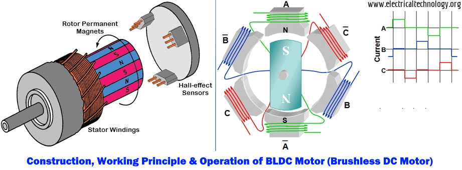
When the stator coils are electrically switched by a supply source, it becomes electromagnet and starts producing the uniform field in the air gap. Though the source of supply is DC, switching makes to generate an AC voltage waveform with trapezoidal shape. Due to the force of interaction between electromagnet stator and permanent magnet rotor, the rotor continues to rotate. when the motor stator is excited based on different switching states, the switching of windings as High and Low signals, corresponding winding energized as North and South poles. The permanent magnet rotor with North and South poles align with stator poles causing motor to rotate. motor produces torque because of the development of attraction forces (when North-South or South-North alignment) and repulsion forces (when North-North or South-South alignment). By this way motor moves in a clockwise direction.
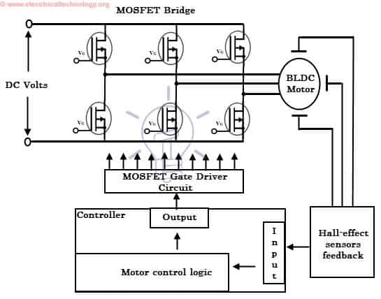
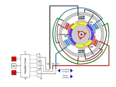
a hall effect sensor is placed inside the motor which determines the positioin of the rotor ie the permanent magnet, by identifying the position the controller would be able to energize the
appropriate motor winding by turning transistor or other solid state switches to rotate the motor continuously, Hall-effect sensors generate Low and High level signals whenever rotor poles pass near to it. These signals determine the position of the shaft.Based on this signal from sensor, the controller decides particular coils to energize. The electronic controller can be a microcontroller unit or microprocessor or DSP processor or FPGA unit or any other controller. This controller receives these signals, processes them and sends the control signals to the MOSFET driver circuit.In addition to the switching for a rated speed of the motor, additional electronic circuitry changes the motor speed based on required application. These speed control units are generally implemented with PID controllers to have precise control