Week -2
AIM
1. To make a simulink model of doorbell using solenoid block
2. To make a simulink where in thermister is used to sense the temperature of heater and to turn ON and OFF fan as per conditions
OBJECTIVE
1. To make a simulink model of doorbell using solenoid block and create a simulation when the switch is closed for 2 seconds an then released,
observe the physical movement of the plunger
2. To make a simulink where in thermister is used to sense the temperature of heater and to turn ON and OFF fan as per conditions,
temperature source : 20
1. REPORT
simulink model of a door bell
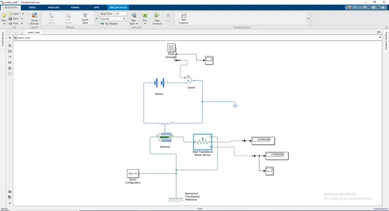
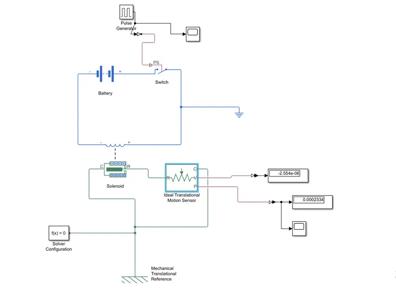
. The solenoid which is an electromechanical device, requires electrical energy produce a mechanical translational movement. the electric current when flows through the coil windings produces a magnetic field which results in the movement or physical displacement of the plunger
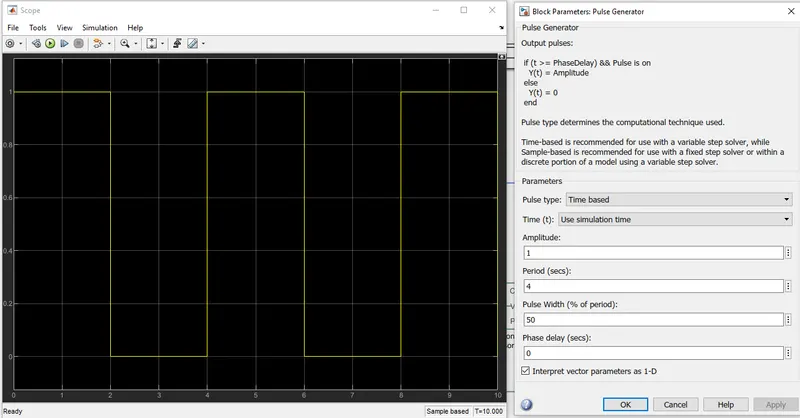
. As per the requirement the switch when closed for 2 seconds and then released', to simulate this a pulse generator is used, where the signals can be determined, where the period is set to 4 seconds as the pulse width is of 50% for a square wave which identically represents that in its 50% of its period it would be on and and the rest it would be off.
. A Simulink to PS converter is used to convert the digital signals produced by the pulse generator as physical signals which are to be fed to the switch block that accepts it as the input signals and act accordingly, ie makes and breaks the circuit according to the signals
. The battery source provides with the voltage required by the solenoid to function, which is controlled by the signals via using a switch as the controlling hardware
. When the solenoid is actuated ie when the plunger is moved due to magnetic force generated, the motion is detected using a ideal translational motion sensor which is capable of detecting the magnitude and the velocity of the displacement , the sensor outputs are physical which is converted to digital signals using a ps to simulink converter and the values are displayed in the display block
. By connecting a scope to the pulse generator and motion sensor the outputs can be recorded which are plotted as a graph and displayed form which the observations and conclusions could be conducted
. Mechanical translational reference and solver configuration blocks are added to the solenoid and motion sensor connections, which helps the solver
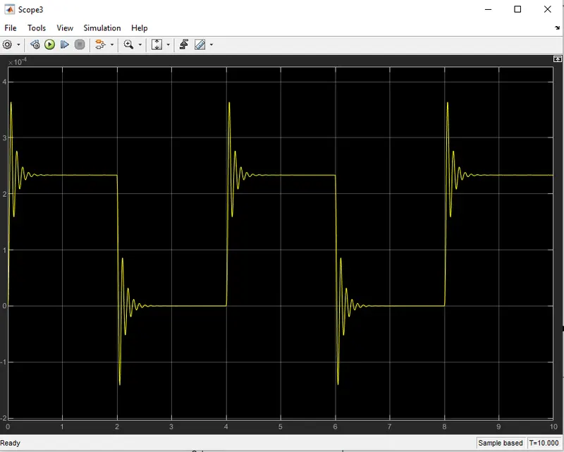
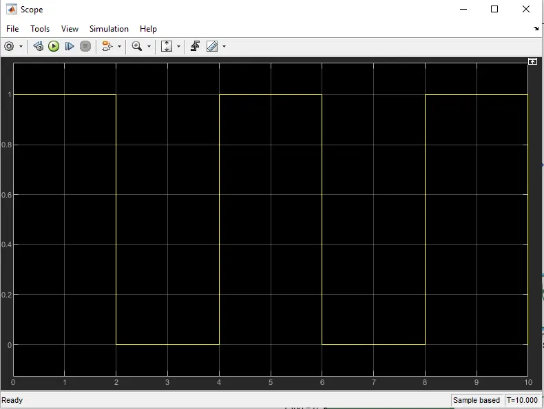
. The image 'Scope3' is the output from the scope ie connected with the motion sensor output which reads the displacement of the plunger of the solenoid,
. The image 'Scope' is the output from the scope connected withe output of the function generator
. From the above plots it can be observed that when the digital signal output is ON the plunger moves which is due the switch which makes the circuit complete that enables the current flow and coil windings energize to produce magnetic field which in turn make
moves the plunger, the movement is read by the sensor which is evident on the graph in the time 0s to 2s where the amplitude is 1
. The initial vibrations are due to the sudden movement of the plunger and and the vibration is damped out gradually as it acquires equilibrium and when the signal output changes to OFF condition from time period 2s to 4s the switch breaks the circuit that denergizes the coils and demagnetises which results in the movement of the plunger to its mean positon or its initial position which is represented which causes initial vibration sthat are gradually dampedout once it reaches equilibrium, this whole process or simulation is carried out fro 10 sec duration
2. REPORT
simulink model of heater control system
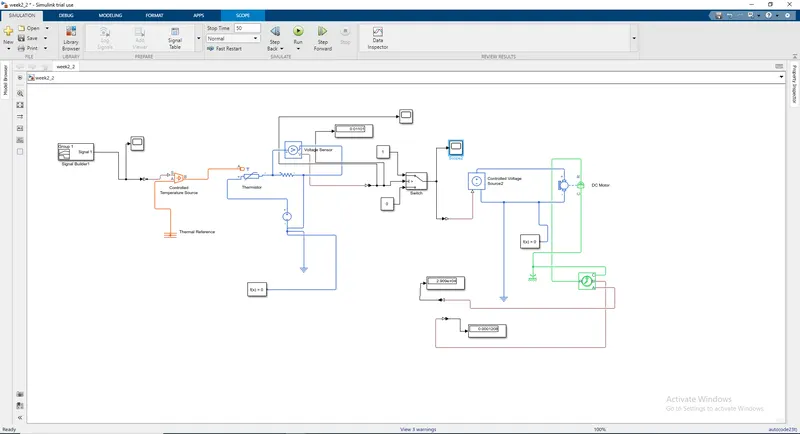
. The heater control system blockset consists of a controlled heat source, which is controlled by the inout signals that are produced by the signal generator.
. To analyse the temperature output a thermistor is used
. The output from the thermister is further used as the reference from which the motor control system is based
. A voltage sensor and a switch are used as the hardware which govern the current supply to the motor or the fan
. A roational sensor is used to detect the working of the fan or the motor
. A simulink to PS converter is used to convert the digital signals into physical signal input to the temperature source and the digital outputs from the switch to controlled voltage source
. To convert the physical signal output from the voltage sensor to the switch a PS to simulink converter is used
. Solver configurations and electrical connections are attached in the electrical circuit connections for the solver to equate
. A mechanical reference is attached in the connections of the motor mechanicals and the motion sensor
. The physical signals from the motion sensor is converted into digital signals so as to connect to the display block which displays the outputs form the sensor
. A resistance is connected in parallel with the voltage sensor as the ideal voltage divider circuit demands a resistance to be connected
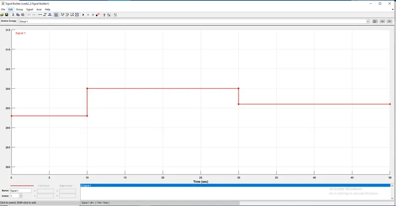
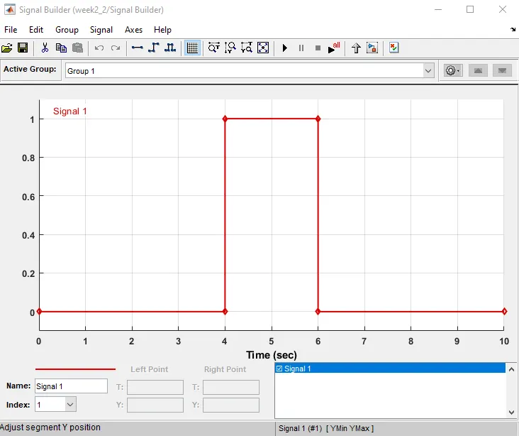
. The signal generator generates digital signals which is used as the input to the controlled heat source which works accordingly, the digital signals are to be configured so as that it works as per the requiremnet or the criteria defined
. As per the criteria in the time period 0s to 10s the output temperature should be 20 degree celsius, and form time 10s to 30s the temperature output should be 27 degreecelsius, from 30s to 50s the temperature output should be 23degreecelsius
. The signals attributes are defined in the signal generator box, where initially its time or the duration is defined ie 50s, from there the time intervals are selected which is on the x-axis and the temperature ranges are on the y-axis which are to be specified accordingly
. The image above on the left represents how the signals are after the attributes are defined and the image on the right defines how the signals are before its defined
. Once the signal is defiend its fed as the input via a simulink to PS converter as the input to the controlled temperature source, which acts or produces the temp accordingly
. The temperature produced by the temperature source is measured by the thermister
. The thermister requires electric current to function which is provided by the voltage source, and the output from the heat source is connected to the thermister, the thermister regulates the voltage output depending upon the temperature which is fed into it, the voltage sensor reads the output from the thermister , which also requires an electrical supply to function, gives output to the switch which is provided so as a control device for the working of the fan
. As per the requirement the fan should only function or work when the temperature exceeds 25 degreecelsius, so to satisfy that criteria, the slider switch is used where a threshold value is defined where it acts as a conditional parameter upon which it should generate output , the threshold value is learned by simulating the system with constant input value as required
. Once the switch is configured the connections to the fan are looked into, where a controlled voltage source is used to provide the voltage to the fan
. The output from the switch is taken as input by the controlled voltage source via a simulink to PS converter, once the signals are provided the voltage source provides the voltage to the fan
. A rotational motion sensor is used to detect the motion or working of the fan, which physically detects it and provides a physical output which is converted via a PS to simulink converter that digitizes the signals and displays it
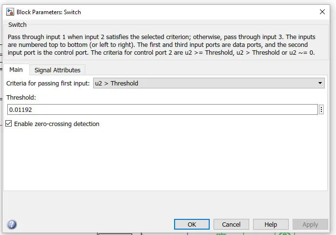
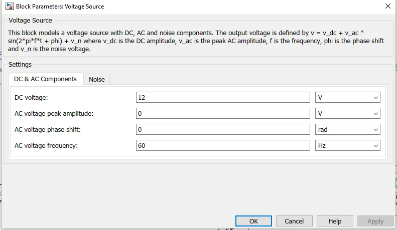
. parameters configured in switch an dvoltage source box,
. The image on the left threshold voltage value over which the switch should generate signals
. the image on the right the voltage output value to the thermister and the voltage source
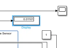
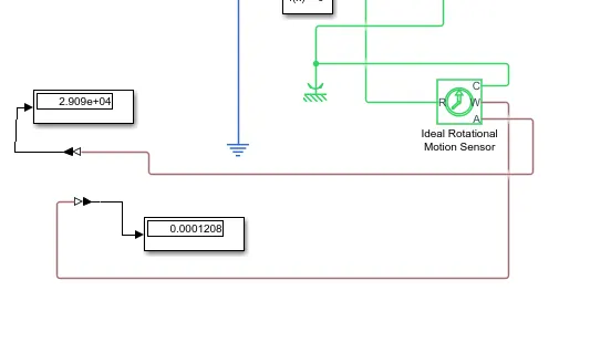
. the outputs from the sensors
. on the left o/p from the voltage sensor and on the right the output from the rotaional motion sensor
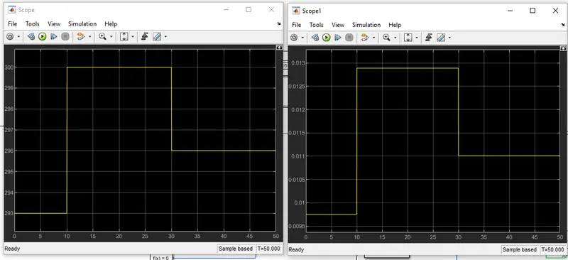
. Outputs from the scope connected to the signal generator and the voltage regulator
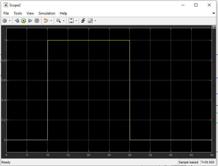
. Outputs from the scope connected with the switch, it produces a on signal in the time period of 10s to 30s where the temperature genetrated is 27degreecelsius and the parameter given to it was to switch on the fan when the temp exceeds 25degreecelcius
CONCLUSION
. The simulink model for the doorbell using simulink block and temperature source control using thermister was modelled and the simulations were carried out with the provided criteria and the results were obtained
. This exercise helped in the understanding of the various electromechanical blocks and the systems in the simulink and their behaviour and the connections were are learned