Week - 4
AIM
Implement the control logic of a 'washing machine' using stateflow
OBJECTIVE
.if the power supply is available, the system gets activated
.if the water supply is not available, stop the process and indicate through LED
.Soaking time should be 200s, followed by the washing time of 100s
.then rinsing happens for next 20s and dryer runs for 50s
.after all process have completed turn on the finish LED
STATEFLOW
stateflow provides a graphical language that includes state transition diagrams, flow charts, state transition tables,and truth tables.
stateflow can be used to describe how matlab algorithms and simulink models react to input signals, events and time based conditions
with Stateflow, its possible to model combinatorial and sequential decision logic that can be simulated as a block within a Simulink model or executed as an object in MATLAB. Graphical animation enables you to analyze and debug your logic while it is executing. Edit-time and run-time checks ensure design consistency and completeness before implementation.
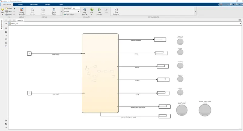
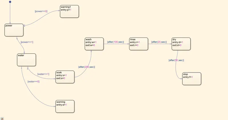
. by using the keyword chartflow searchspace the stateflow chart is accesed,
. after entering into the chartflow space, the states required are created or defined which are represented as block sets, specific name for the each blocks are mentioned to recognize the states
. the states are defined as per the logic,power,water, soaking, washing,rinsing and drying,and stop
. the each state would have an output variable assigned to it
. the inputs are assigned using a constant block where it gives a constant value1 as input, ie to replicate the situation where there is constant water and power supply when triggered by a switch
. the initial state is power, where the program checks for the power source,
. the conditions for the each state is specifically mentioned, according to the conditional statement the state when it has power supply the logic statement becomes true, then it will move on to next state , if else the logical statement becomes false it will break the chain and move on to warning1 block where it will trigger the warning message via a LED
. the conditional statements are specified individually for each block for every state, which decides how to proceed with the program logically
. if the power supply is on the condition or logical statement power==1 becomes true and it will proceed to the next state water
. after entering into the next state 'water', it checks for the water supply, if the system has water supply the statement water==1 bcms true , it will proceed further to next step ie soak
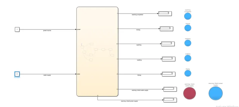
. if the water supply is not active, the condition water==0 becomes true and it will jump onto warning state and will break the program by displaying the warning message via a LED
.when the wayer supply and the power source are active the washing cycle will start, which starts with filling of water and detergent into the washing tub and soaking of the clothes start
. soaking process continues for 200 seconds, before the program moves on to next state, this is called as time-dalay parameter. where the movement of the program is based upon time determined
.after soaking process is completed it moves on to next state washing, which continues for 100seconds, after the washing it moves on to rinsing which continues for 20seconds, after which it moves to last state whihc is drying which continues for 50seconds
.after all of this is completed the washing process concludeds and program moves on to next state end, where the program informs the user that the process have been completed via a LED
.the system is simulated for 500seconds
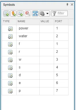
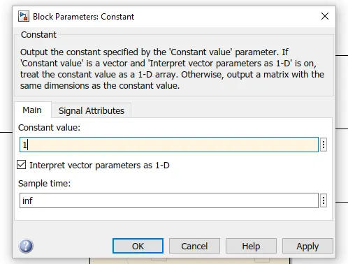
. Each state has an output variable, the output port takes the output from these variables and displays it on the display block through which the LED is connected,
. from the confirugation dropbox, the symbols plane box is acessed through which the variables are configured. the symbols box will recognize the variables and displays them in the box,
. the variables are configured, nature(input/output), which then is assessed by the program to determine the input and output sources
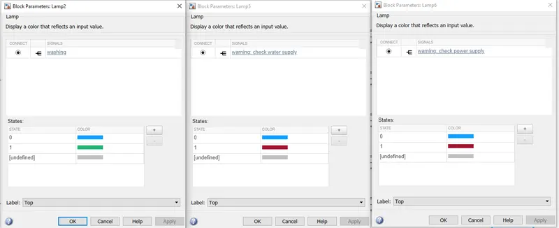
. the LED's are configured as such, it would turn green when the state is true or selected and would remain blue when its idle.
. the warning LED's are configured so as that it would turn red when the condition is true in for warning and would be blue in colour when its idle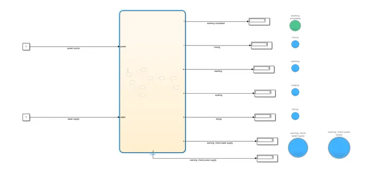
. the outputs from the variables are available at the output ports, which are taken and connected to a display box which displays the logic, ie (true or fales// 1 or 0) , via which the LED is connected, which displays the determined color, for both cases (true or false)
through which it can be learned which state is currently being processed or anyother warning or message is being sent to the user by the system, basically its the interactive space for the machine and the user
. it displays green when the case is true or 1, which happens when the program enters the corresponding state, eg when the system is in washing state the LED, for washing will turn green, and viceversa
. if there is any problem with the power and water supply the warning LEDs will turn on, it turns RED , thus letting the user know to check for water or power supply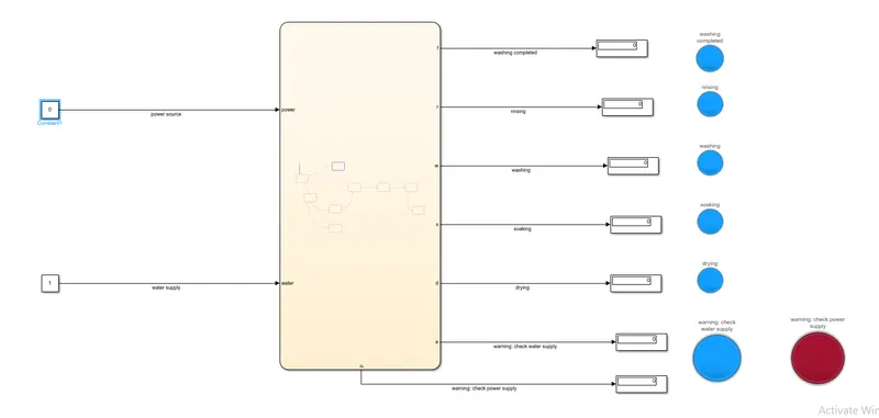
2. AIM
make a simulink chart for gear shift logic
OBJECTIVE
speed range gear
0 to 15 1
16 to 25 2
26 to 40 3
41 to 60 4
above 61 5
give speed input while the simulation is running and display the gear number
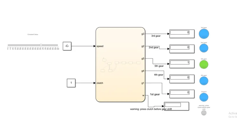
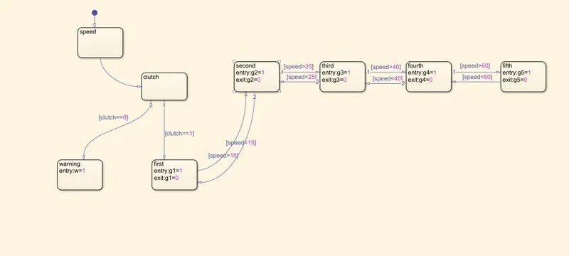
. the gear shift logic is depended upon the input speed, the gears need to be upshift and downshift depending upon the speed ranges.
. a parameter 'clutch' is used in the system which is used as a conditional parameter,
.the speed is taken as an input via input port, which is provided by a constant block connected with a slider gain to satisfy the input parameter ie
'give the speed input while the simulation is running and display the gear number'
. the slider would vary the output value corresponding to the slider posiiton, it has variable values depending upon the position of the slider
. the output of the slider is taken as the input by the constant block via which the value is being fed as constant to the stateflow system, even while the simulation is running in the background
. the clutch input is given as constant value using a constant block , which ideally replicates that the clutch is being disengaged before the gearshift is initated
. as the speed input enetrs the stateflow system its taken in by the block 'speed', after which it moves to another state which is 'clutch'
. in clutch it moves to next state only if the clutch is pressed, which satisfies the condition clutch==1
.if not then'clutch==0' becomes true which will move the program to another state , which will warn the user for the same via a LED
.after the clutch condition bms true it moves on to another state ie the 1st gear where it checks for the speed, wether the criteria is fit to engage the selected gear
.it checks for the criteria, ie the speed range, it would switch the states according to the criteria , would select the respective gears and would select the states respectively.
.as the program switches to the states upon speed range it would indicate the user via a display box and an LED, as the output variable generates ouput value only when the state is selected or when its in use currently
.when the current speed does not fit the present state it would check for the value of speed input, if it is greater than the current speed criteria for the state or if its low, then it would move to the corresponding state depending upon the current speed value,
its the logic for upshift and downshift of the gears, as the speed varies.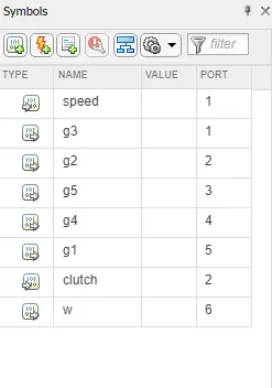
. the variables are read automatically by the system, which are then to be defined by the user wether its input or an output, upon which the system redesigns the blocks and determines the input and the output ports
. the input and the output values are given and obtained from the respective ports
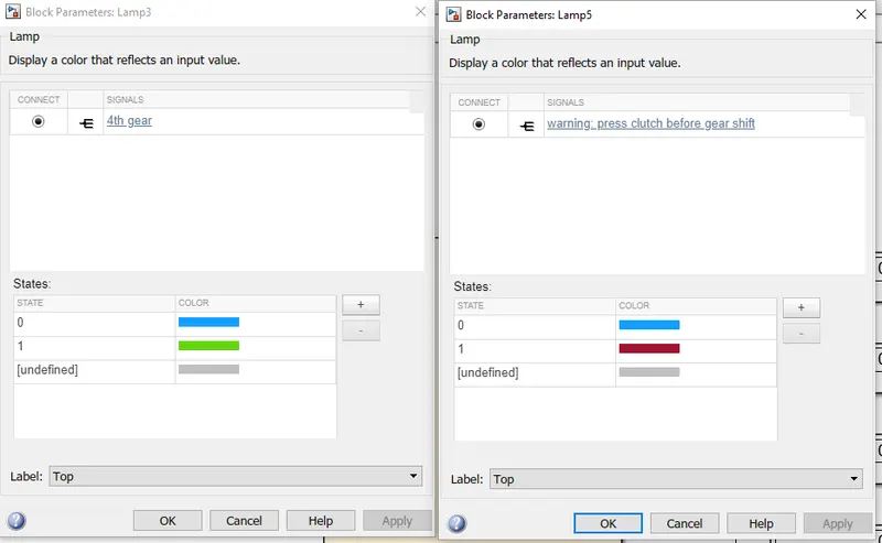
. the LED's are configured as such, it would turn green when the state is true or selected and would remain blue when its idle.
. the warning LED's are configured so as that it would turn red when the condition is true in for warning and would be blue in colour when its idle
- give speed input while the simulation is running and display the gear number
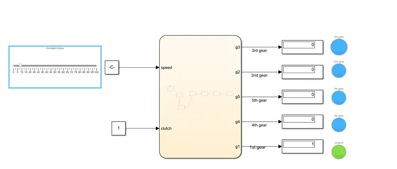
. the LED respective to the 1st gear is indicated when the slider position corresponds to 7kmph , and the display box also displays the value 1 when the state 'first' is selected
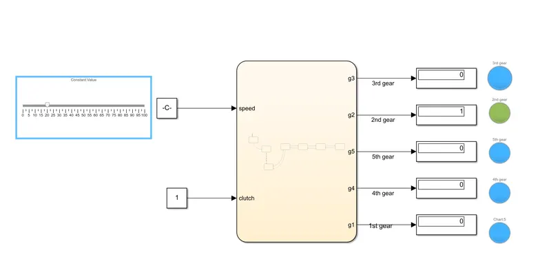
. the system recognizes the change of speed and switches to another state respective of the changed speed and upshifts to 2nd gear as the slider position points to 20kmph and indicates the current state selected via the display box and the LED
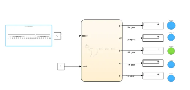
. the system recognizes the change of speed and switches to another state respective of the changed speed and upshifts to 5th gear as the slider position points to 67kmph and indicates the current state selected via the display box and the LED
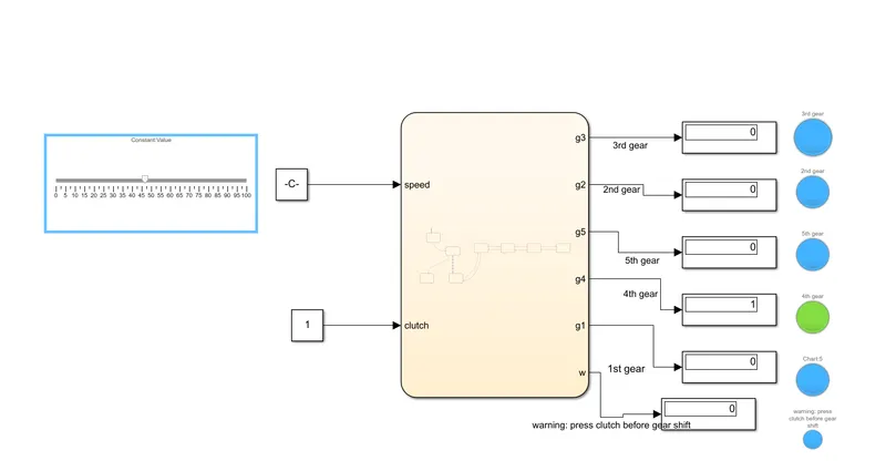
. the system recognizes the change of speed and switches to another state respective of the changed speed and downshifts to 4th gear as the slider position points to 46kmph and indicates the current state selected via the display box and the LED
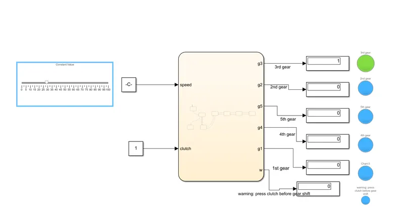
. the system recognizes the change of speed and switches to another state respective of the changed speed and downshifts to 4rd gear as the slider position points to 28kmph and indicates the current state selected via the display box and the LED
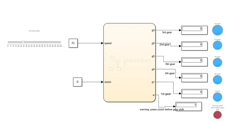
. the warning indication being displayed using the LED and the display box as the clutch is not disengaed, which is simulated by giving the value of clutch input as zero that replicates the scenario as clutch pedal not pressed and satisfies the condition 'clutch==0'