Week-7 Challenge: DC Motor Control
Question 1:
Solution:
Objective: The aim of the assignment is to:
a) run the H-Bridge Model so as to observe the variation in Speed of the DC Motor.
b) decrease the peak value of the armature current draws by the DC Motor when its changes its direction from Forward to Reverse.
Introduction:
The controlling of the Speed of the DC Motor is a very importatnt criteria for various application perspective. From controlling the Speed of the car to the operation of the Pump or the Fan, achieving the right speed at the right moment is outmost important. There are few mechanism through which we can achieve the Speed Control of the DC Motor which are as follows:
- Armature Resistance Control through Rheostat.
- Field Flux Control by varying the Magnetic Field Intensity.
- Variable Voltage Control or Controlling the applied voltage.
In our's case, we have choosen the third one which is the Variable Voltage Control and it is achieved by using BJT H-Bridge Model where a fixed voltage DC source is getting converted into a Variable Voltage DC output(Average Output Voltage) by changing the Duty Cycle of the pulse generated from the BJT Power Converter. This phenomenon of varying the Duty Cycle is also known as Pulse-Width Modulation(PWM) technique where the width of the pulse is controlled which is nothing but the ON-time of the particular BJT by keeping the Total Time fixed. Using the above technique not only the the Speed of the DC Motor is controlled but also we can change the direction of the Motor in both Reverse and Forward direction.
Circuit Diagram:
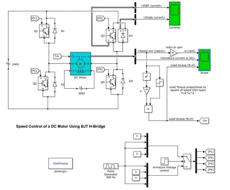
In this project we have choosen a DC motor having a specifications of 5HP,240V,1750RPM with a Field Voltage of 300V. This Motor is connected across Four IGBT switches with a Forward Voltage of 1V and On-State Resistance of 0.001`Omega`. The Free-wheeling Diode is connected to by pass the high reverse current when the corresponding IGBT switches are in OFF position. As there is no option of giving respective Duty Cycle to each IGBT power converter, so an arrangement of Pulse Generator of 500Hz and Armature voltage is made seperately and according to the combination a pair of IGBT switches are triggered by activating the corresponding Gate of the switch.
Working Principle:
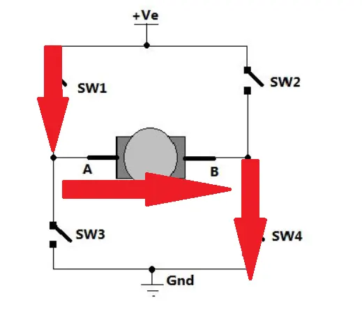
The H-Bridge Model is working in the following fashion and i.e. initially the IGBT Q1 and Q4 are triggered so at that condition the current is flowing in the following direction as shown below:
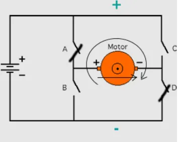
Here the DC Motor works in Forward state as shown below:
After that the IGBT Q1 and Q4 goes to OFF state and in the situation when all the switches are OFF a high amount of Reverse current will flow from the Motor due to the inductance behaviour of the Motor and in order to bypass the current the Free-wheeling diode will act in that situation which in this case is D3 and D2.
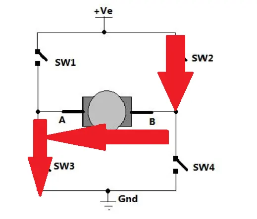
Similarly, during the second pulse the IGBT Q3 and Q2 will get triggered and the current flowing will be opposite from the figure shown above as shown below:
Here the motor direction will get reverse as shown below:
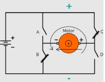
Similarly after the Duty Cycle gets over the IGBT Q3 and Q2 goes to OFF state and to handle the excessive reverse current the Free-wheeling diode D1 and D4 acts to bypass the reverse current.
This is the overall working principle of the H-Bridge Power Converter Model.
Results and Discussion:
Initially at 75% Duty Cycle, the armature current and corresponding Speed and Load Torque Curve is coming as follows:
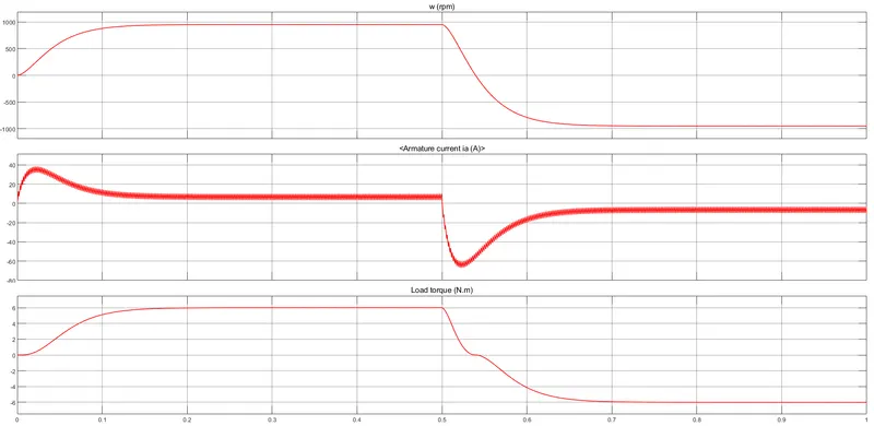
Here we can see that though the Speed and the Torque of the Motor reaches at a decent level but during the changing of the direction the Motor draws a huge amount of current that can be analyse from the negative spike of the armature current curve which can be sometimes become not permissible. So in order to reduce that we just have to decrease the Turn-On time of the Power Converter by decreasing the Duty Cycle.
Changing the Duty Cycle to 50% and the corresponding results are shown as follows:
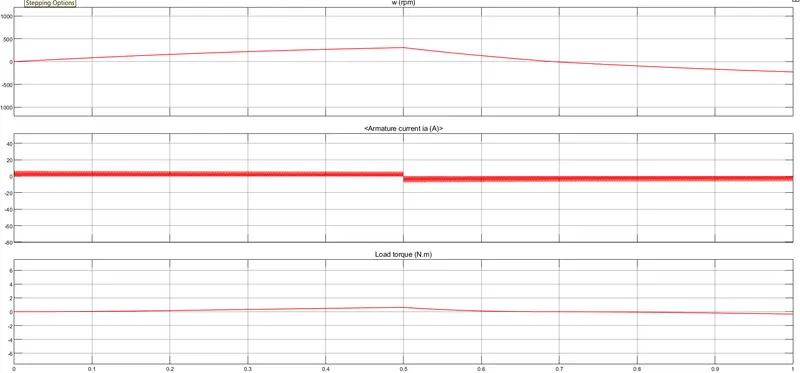
Here the Current consumption by the Motor gets drastically reduced but on the other hand the Speed and the Torque performance gets hugely compromised. So for the purpose where its required less torque and speed then it is always preferable to run the model at less value of Duty Cycle.
Question 2:
Solution:
The Four-Quadrant DC Chopper Block of Matlab is a modified DC supplied Chopper Block that is used for DC Motor drive and its Speed Control. The arrangement is more or less same as that of the BJT H-Bridge Model but the main difference falls on the arrangement for triggering the Base of the IGBT circuit which in this case is done using a PI controller through which the Chopper duty cycle corresponding to every armature current is derived. This duty cycle is then compared to a reference saw-tooth/triangular signal to generate a PWM signal for driving each of the Chopper gate circuit. The corresponding DC Chopper Block in Matlab is represented as following:
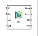
The entire arrangement of the Four-Quadrant Chopper using the IGBT power converter is shown as following:
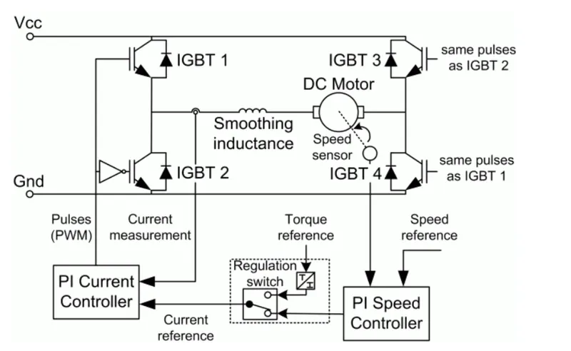
Unlike the H-Bridge Model, here each of the IGBT gate is driven using a PI current controller by constantly monitoring the armature current generated from the corresponding Torque and Speed reference.
Advantage of Four Quadrant DC Chopper over H-Bridge Model:
- As compared to other DC drives, this Chopper arrangement can able to operate the DC Motor in all the Four Quadrants i.e Forward Motoring, Reverse Motoring, Forward Regenerative Braking and Reverse Regenerative Braking.
- For having a high switching frequency, these Chopper circuit arrangement will produce less armature current ripple than other Thyristor based DC drives.
- Controlling the armature current gives the Four Quadrant Chopper an extra advantage over other DC Drives.
Disadvantage of Four Quadrant DC Chopper over H-Bridge Model:
- Complexity of Four Quadrant Chopper is more than the other DC Drives.
- Presence of interrupted conduction current that leads to non-linear charateristics in all the Four Quadrant.
Question 3:
Solution:
Objective:
The aim of this experiment is to create a model using Four-Quadrant Chopper DC Drive(DC7) Block which is required to drive the Motor of the Electric Vehicle(EV) system with its own Driving Cycle as a Speed Reference.
Introduction:
The Four-Quadrant Chopper also known as Class-E Chopper is the only type of arrangement which is capable of operating in all the Four quadrants. In this scenario, the power produced can flow either from source to load or from load to source depending on the condition of operation. When this arrangement works in the First Quadrant it acts like a Step-Down Chopper whereas when it works in the Second Quadrant it acts like a Step-Up Chopper. Here all the IGBT's are triggered using Pulse Width Modulation(PWM) Technique. This Chopper arrangement is then connected to a seperately excited DC Motor whose having a Field resistance of 300`Omega` and an Armature resistance of 0.076`Omega`. This simulated model is then implemented as applicable to Electric Vehicles that is analysed under various speed conditions corresponding to the Driving Cycle defined by the user.
Model Circuit Diagram:
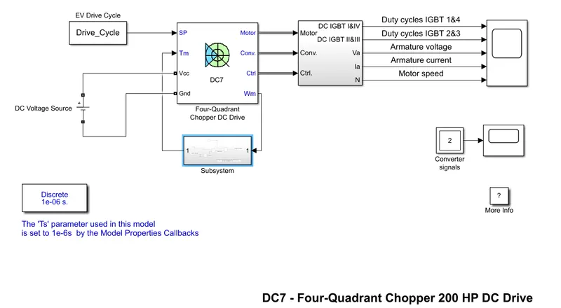
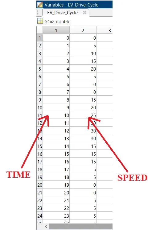
Through this Model we alos represented an EV Model scenario, which is done by connecting a Battery of 515V between Vcc and Ground(Gnd) of the DC Drive Block and also we have implemented a seperate Drive Cycle where the values of the Speed and Time has defined from the Workspace as shown below:
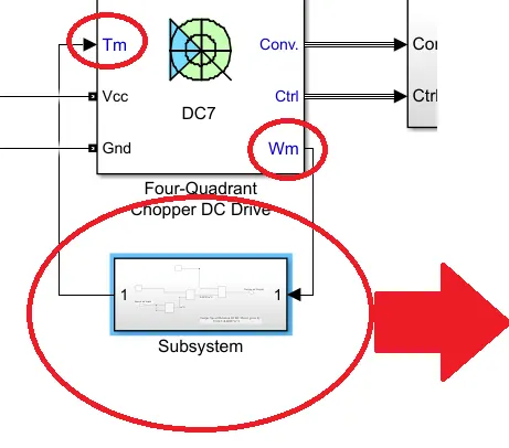
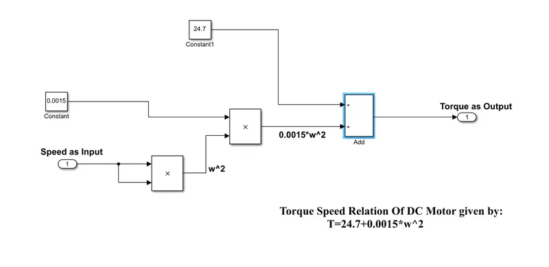
We know the Torque-Speed Relationship of a DC Motor is given by:
`T=24.7+0.0015*omega^2`
This relationship is then implemented in a different Subsystem between Wm(Speed) and Tm(Torque) of the DC Drive(DC7) Block. The Blocks used in the Subsystem is shown below:
Working Principle:
Basically the Circuit of a Class-E or Four-Quadrant Chopper consists of Four Semiconductor switches along with Four Diodes which are placed antiparallal to the corresponding switches. The Circuit Diagram of a simplified Class-E Chopper is shown below:
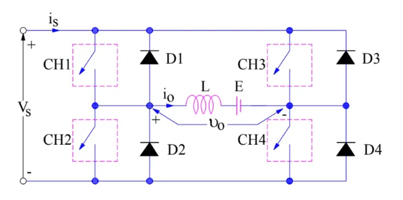
Here in the above circuit diagram the Choppers are numbered from CH1 to CH4, for better understanding we will discuss the operation seperately for each quadrant.
- First Quadrant Operation:
For first quadrant operation, CH4 is kept ON;CH3 is kept OFF and CH1 is operated. In this scenario when the CH1 is ON, the load gets connected to the source voltage therefore v0=Vs and current(io=is) flows in the same direction through CH4 back to the source. When CH1 gets OFF then the loads gets disconnected from the source and the Inductance changes its polarity(to oppose the cause) and the current flows through CH4 and freewheels through the diode D2. Therefore both the current and the voltage are positive w.r.to the point of direction and polarity, and its act exaclty as a Step-Down Chopper.
- Second Quadrant Operation:
In this scenario, all the switches are kept OFF except CH2 which will be operated. When CH2 is ON, the current will flow from the DC source E through CH2 and D4 in the opposite direction to that of io, in this case the Inductor L will stored energy. When CH2 is OFF, the Inductor L will change its polarity so v0 becomes Ldi/dt+E > Vs; so the current will flow from v0 through D1 and D4 and in this case also the current is flowing opposite to that of io. Therefore the Voltage polarity stays positive but the current gets negative w.r.to io and this way it becomes a second quadrant operation similar to that of a Step-Up Chopper.
- Third Quadrant Operation:
For Third and Fourth Quadrant Operation, the first thing is to change the polarity of the DC Source E in opposite direction as shown below:
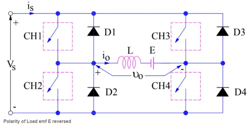
So during Third quadrant operation, CH1 is kept OFF; CH2 is kept ON and CH3 is operated. When CH3 is ON, the source voltage gets connected to the load voltage but in opposite polarity w.r.to the polarity v0 as shown in the circuit. The current flows through CH3 and CH2 and it is in opposite direction to that of the load current io, so both direction of current and the polarity of voltages are opposite to each other. When CH3 is OFF, then the Inductor L will change its polarity and the current will from CH2 and freewheels through D4 and the source will get disconnected from the Load. So, in both the scenario both the current io and the voltage v0 is negative.
- Fourth Quadrant Operation:
For Fourth quadrant operation, all the switches are kept OFF except CH4 which will be operated. When CH4 is ON, current will flow from the DC Source E through CH4 and D2 and it is in the same direction as that of io however the voltage v0 will be negative because of the opposite polarity to that of E. When CH4 goes OFF, the Inductance L will change its polarity so load voltage becomes Ldi/dt+E but negative to that of the v0 polarity and the current will flow through D3 and D2 in the same direction to that of the Load current io. So in this scenario io is always positive but v0 is negative, and thus its a fourth quadrant operation.
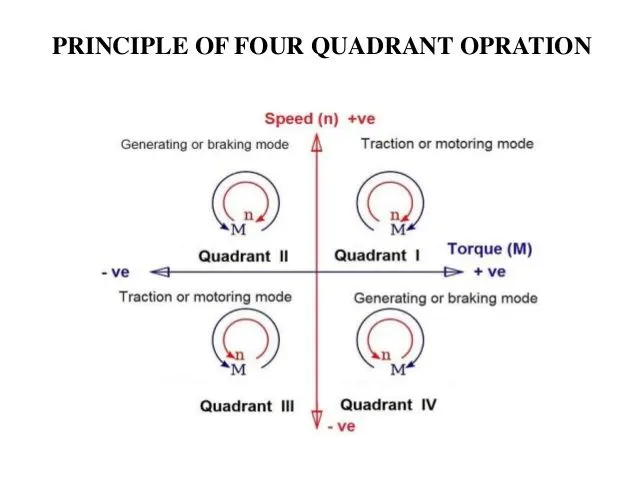
So therefore overall the Four-Quadrant Chopper operates in all the four quadrant efficiently which can be summarized with the help of a figure given below:
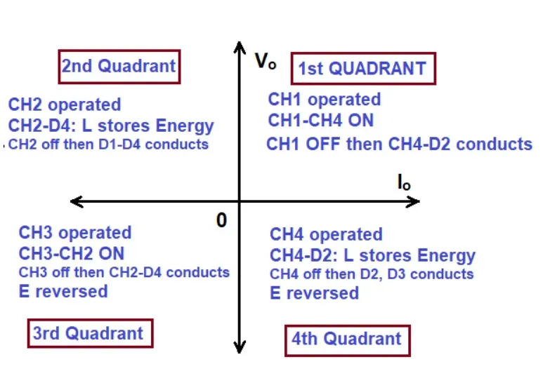
Now with this Chopper arrangement when the DC Motor will get connected then its Speed and Torque will vary along with the respective Quadrant operation of the Chopper which can also be summarized as follows:
Results and Discussion:
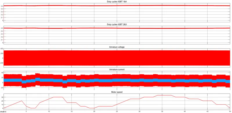
The results are coming as follows:
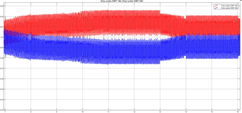
Regarding the IGBT 1&4 and 2&3 if we take a closer look then it is coming as follows:
If we zoom the armature voltage and current it coming as the following:

Here the following discussions can be made from the above results:
- IGBT 1&4 and IGBT 2&3 are acting somewhat complementary with each other and this is the exact case happening when the Chopper arrangement and the DC Motor is working in the 1st and Fourth quadrant. However, the merging of the IGBT curve is occuring due to the Second and the Third Quadrant operation when only one switch is operating at a time. The duty cycle of the switches are ranging from 0.45 to 052, form here we can say that the duty cycle is maximum when the speed of the DC Motor reaches its maximum speed as defined in the Drive Cycle and after that when the speed of the vehicle reaches to zero then the duty cycle of the corresponding switches also reaches to a minimum value of 0.45. Thus from the above statement we can infer that duty cycle is directly proportional to the speed of the vehicle which is because of the fact that by controlling the the duty cycle we are actually controlling the voltage required to drive the motor. So as voltage is proportional to the speed of the Motor so thats why duty cycle is also gets proportional to the speed of the Motor.
- Regrading the Armature Voltage, from the curve we can clearly get an idea that it is produced due to the switching action of the IGBT switches using the PWM technique. Due to higher switching frequency the armature voltage will fluctuate because of the change in direction of the voltage corresponding to the Quadrant operation of the switches. So thats why the armature voltage fluctuates between the positve and negative part of the curve and w.r.to that the Motor will operate either in the Motoring Mode or in the Braking Mode.
- Corresponding to the armature voltage the armature current will also fluctuate at a higher frequency. From the nature of the current it is quite obvious that its magnitude will be more when the vehicle will run at a higher speed because at that time the Torque required to drive the vehicle will be more and gradually the maximum and the minimum armature current will get reduce when the speed of the vehicles will fall to a minimum value. Thus, from here we can clearly say that it is exaclty following the Drive Cycle defined by the user
- Regarding the Motor Speed it is simply the angular speed plotted w.r.to time, so thats why we can see that it is exactly equal to the EV Drive Cycle as defined by the user. So higher the speed of the Motor higher amount of Power will be required to drive the Motor and so the magnitude of the armature current gets increased to a maximum value.
Question 4:
Solution:
A Brushless DC Motor(BLDC) is basically an electronically commutated DC Motor without brushes and they are powered by DC electricity through the connection of an inverter or a switching power supply in order to generate electricity in the form of Alternating Current(AC) so as to drive each phase of the Motor by producing a rotating magnetic field around it via a closed loop control system. This controller provides pulses of current to the motor windings which ultimately regulates the Speed and Torque of the Motor. Actually this controller replaces the Brushes used in other conventional DC Motors.
The Construction of BLDC motor is same as that of the Permanent Magnet Synchronous Motor(PMSM). BLDC Motor has a huge advantage over brushed DC Motor in the segment of high power-to-weight ratio, high speed and low maintenence. Practically a BLDC motor basically looks like these:
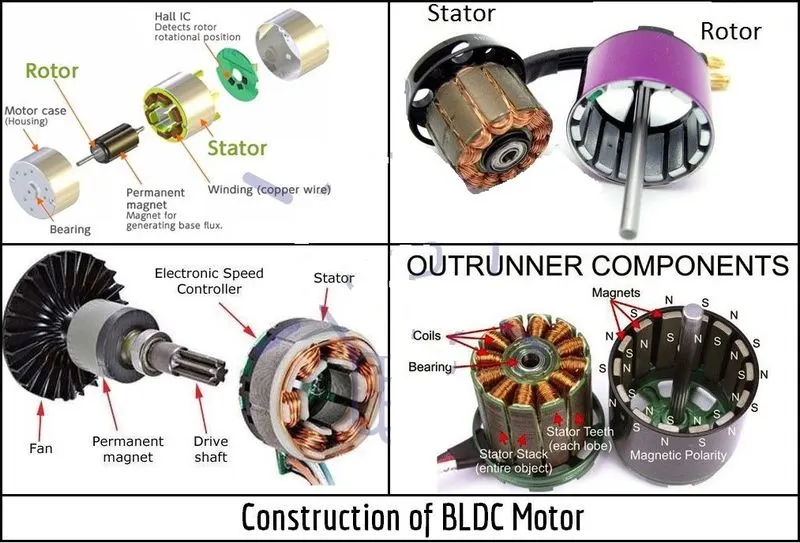
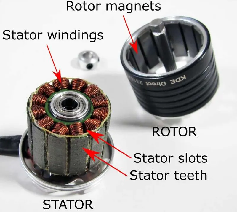
Brushless DC Motor consists of two parts: one is the rotating parts called Rotor along with Rotor magnets which are nothing but permanent magnets and another part is the stationary one called Stator along with Stator windings.These stator windings becomes electromagnets when electricity reaches to it thereby generates the Magnetic Field in the armature. This magnetic field then interacts with the Permanent magnet of the rotor and allows the Rotor or Shaft to rotate at a considerable speed as shown below:
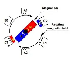
BLDC Motor generally operates due to attraction and repulsion between magnetic poles. It happens in this way that when current starts flowing through the three phase stator windings then it will generates a magnetic pole in the Stator which will attracts the closest permanent magnet of the opposite pole.
Gradually BLDC motor are of two types which are Outer Rotor Motor and the other one is Inner Rotor Motor.
a) Outer Rotor Motor:
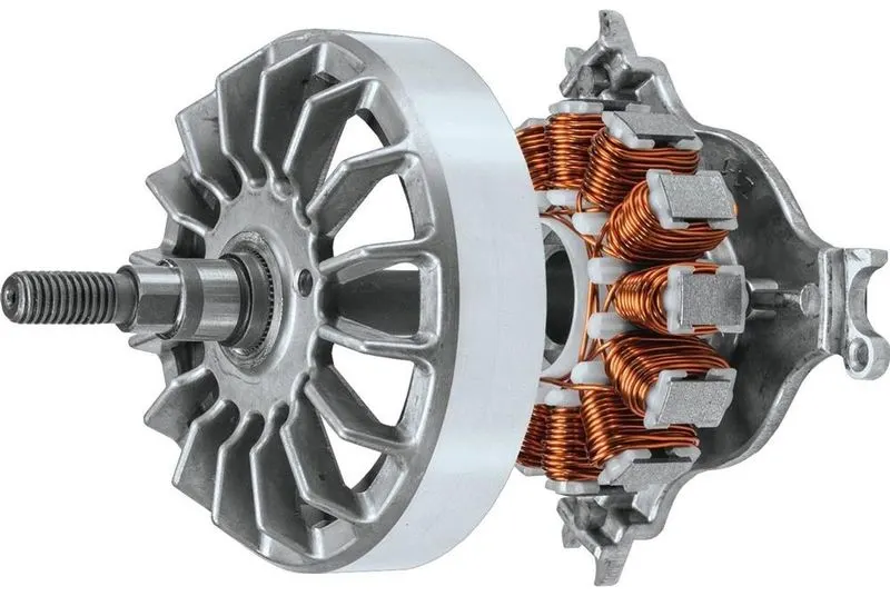
In Outer Rotor Motor the rotor parts of the Motor surrounds the windings which is located in the armature core of the Motor. As the rotor is outside to that of the windings so the magnets in the Rotor trap the heat of the Motor from inside and do not allow to dissipate form the Motor. These type of Motor operates at Lower current rating and therefore has low cogging torque. The construction of such type of Motors is shown below:
b) Inner Rotor Motor:
In these type of Motor design, the Rotor is located at the center of the Motor and the windings of the Stator surrounds the Rotor. As the Rotor is located inside the core so the Rotor Magnets unable to resists the heat of the motor to get dissipated outside. This type of Motor produces a large amount of Torque but very carefully used due to the dissipation effect. The construction of such type of Motors is shown below:
Advantage of BLDC Motor:
- This type of Motor are much more efficient as its speed of rotation is solely depends on the frequency at which the current is supplied, not on the Voltage.
- As they are Brushless so the Mechanical Losses due to friction is negligible therefore increasing the efficiency.
- It can easily operate at High Speed independent of any conditions.
- No Sparking occurs and much less noises are produced during its operation.
- The electromagnets used in the Stator can be increased thereby giving the advantage of more precise control.
- Due to low Rotor inertia of the BLDC Motor, it can accelerate and deaccelerate easily.
- Due to its high performance range it can provide high Torque per cubic inch over a vast speed range.
- As there is no Commutator present so the ionizing sparks and electromagnetic interference can be made totally negligible.
- These type of Motors are basically cooled by conduction and so no air flow is required for inside core cooling.
Disadvantage of BLDC Motor:
- BLDC Motors are more costly than the other Brushed type DC Motors.
- The high power supplied to the Motor must be given in limited amount otherwise too much heat will weaken the magnet and the insulation of the windings may get damaged.
- For Brushless DC Motor, wiring and operation of the Motor is not so simple because of the presence of electronic control devices and its link to all the electromagnets.
- Due to the presence of natural vibration frequency of the BLDC Motor, this frequency sometimes can get match with the vibration frequency of the body or the plastic parts thereby incraeses the chances of the occurence of Resonance phenomenon.
Applications of BLDC Motor:
- Very commonly used in Electric vehicles(EV) and Hybrid Electric Vehicles(HEV).
- Modern Cordless Tools like Timmers, Blowers, etc.
- Used in heating and ventillation purposes.
- Areomodelling like in model aircrafts such as Drones or Helicopters
- Radio Controlled Cars.
REFERENCES:
1] https://www.engineersgarage.com/electronic-projects/dc-motor-control-using-h-bridge/
2] http://www.bulipi-eee.tuiasi.ro/archive/2013/fasc.4/p15_f4_2013.pdf
3] https://electricalbaba.com/four-quadrant-chopper-or-class-e-chopper/
4] https://electricalbaba.com/brushless-dc-bldc-motor/
5] https://electricityshock.com/advantages-and-disadvantages-of-brushless-dc-moto
6] https://en.wikipedia.org/wiki/Brushless_DC_electric_motor