Week-7 Challenge: DC Motor Control
OBJECTIVE 1:
Run MATLAB demo ‘Speed control of a DC motor using BJT H-bridge’. Modify the model such that armature current doesn’t shoot up when motor changes direction from forward to reverse.
Answer :
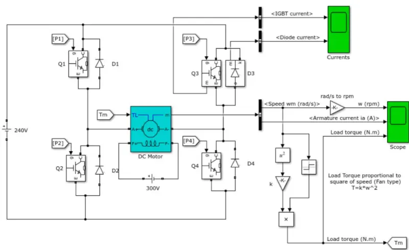
Speed control of a DC motor using BJT H-bridge
This example shows the simulation of an H-bridge used to generate a chopped voltage and to control the speed of a DC motor.
Description:
The Bipolar Junction Transistor(BJT) when used for power switching applications,operates as an IGBT. When it is conducting(BJT operating in the saturated region),a forward voltage Vf is developed between collector and emitter(in the range of 1V). Therfore, the IGBT block can be used to model the BJT device.
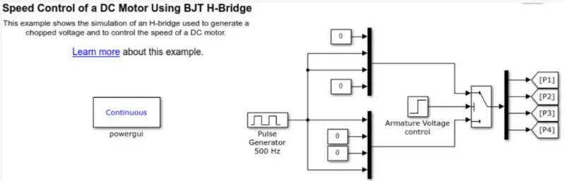
The IGBT block does not simulate the gate current controlling BJT or IGBT.The switch is controlled by a Simulink signal(1/0). The DC motor uses the present model (5HP 24V 1750rpm). It simulates a fan type load (where load torque is proportional to square of speed). The armature mean voltage can be varies from 0 to 240V when the duty cycle(specifiedin the Pulse Generator block)is varied from 0 to 100%.
The H-bridge consists of four BJT/Diode pairs (BJT is simulated by IGBT models). Two transistors are switched simultaneously:Q1 and Q4 or Q2 and Q3.When Q1 and Q4 are fired,a positive voltage is appliedto the motor and diodes D2-D3 operate as free wheeling diodes when Q1 and Q4 are switched off. when Q2 and Q3 are fired, a negative voltage is applied to the motor and diodes D1-D4 operates as free-wheeling diodes when Q2and Q3 are switched off.
Simulation:
The motor starts in the positive direction with a duty cycle of 75%(mean DC voltage of 180V). At t = 0.5 sec, the armature voltage is suddenlyreversed and the motor runs in the negative direction.
Scope shows motor speed, armature current and load torque.
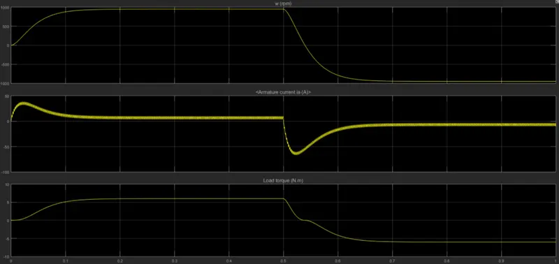
It can be seen from the above graph that the armature current peaks at 50A with the set parameters and when the motor reverses its direction,it goes down to 100 A in the negative axis
This huge volt face in the current value is due to addition of back-emf current to the armature current when the polarity is reversed.
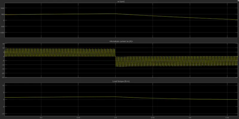
This fluctuation can be mitigated with the help of a RC snubber or by waning the values of Duty cycles.
In this case the duty cycle is reduced to a value of 45% which in turn neutralises the spike in armature current.
Conclusion:
Many of the rise of armature current is reduced by reducing the duty cycle ratio
Q2:Four quadrant chopper Dc drive
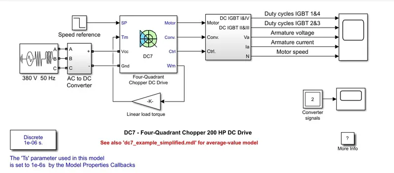
The comparison between Dc7 chopper model and H-bridge model using BJT is as follows:
1. H-bridge model using BJTIGBT-diodepairs.The maximum voltage achieved is 300-350V whereas in DC7 chopper model due to the presence of DC-Ac converters, DC7 model has the privilege to vary the magnitude of voltage to desired level. The maximum value of voltage that can be achieved is 400V which on phase reversal becomes 200V
2.In H-bridge model the Torque and hence output power bandwidthare narroweras it isrestricted to use single pulse generator. where Dc7 chopper motor has a broader range of torque and output power compared to the former.
3.In H-bridge model the range of armature current has lesser values comparatively since only two pairs of IGBT and diode models are functioning at a time whereas in DC7 model the use of four quadrants gives the armature current more degrees of freedom .
Q3:To make an EV Model using DC7 Block:
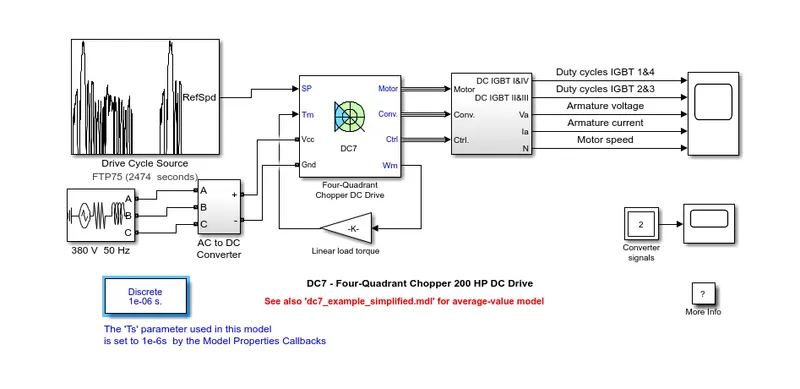
The DC7 Block is modified with addition of blocks to make a suitable EV model
The speed reference is replaced with the drive cycle.
AC source is replaced by the DC voltage source and a current sensor is added in series to measure the flow of current and to view that measure of current a scope is connected.
Linear Torque characteristics block is removed and a new subsystem is created by using the torque equation.
The input of the subsystem is the output speed of the DC7 chopper block,the output of the subsystem block is given to the Torqueinput of the DC chopper block
The resultant graph obtained as follows:
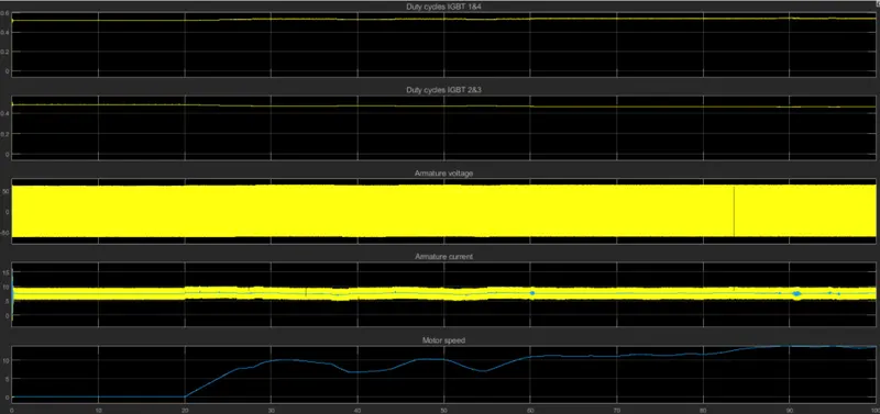
In order to convert the existing DC7 Block into an EV Model , the reference speed block was obviated and replaced with Federal Test Procedure Drive cycle (FTP75). The output sampling time was later changed to 100 seconds.
Q4: Operation of BLDC Motor:
A brushed DC motor has permanent magnets on the outside of its structure, with a spinning armature on the inside. The permanent magnets, which are stationary on the outside, are called the stator. The armature, which rotates and contains an electromagnet, is called the rotor.
In a brushed DC motor, the rotor spins 180-degrees when an electric current is run to the armature. To go any further, the poles of the electromagnet must flip. The brushes, as the rotor spins, make contact with the stator, flipping the magnetic field and allowing the rotor to spin a full 360-degrees.
A brushless DC motor is essentially flipped inside out, eliminating the need for brushes to flip the electromagnetic field. In brushless DC motors, the permanent magnets are on the rotor, and the electromagnets are on the stator. A computer then charges the electromagnets in the stator to rotate the rotor a full 360-degrees.