Week-7 Challenge: DC Motor Control
1)
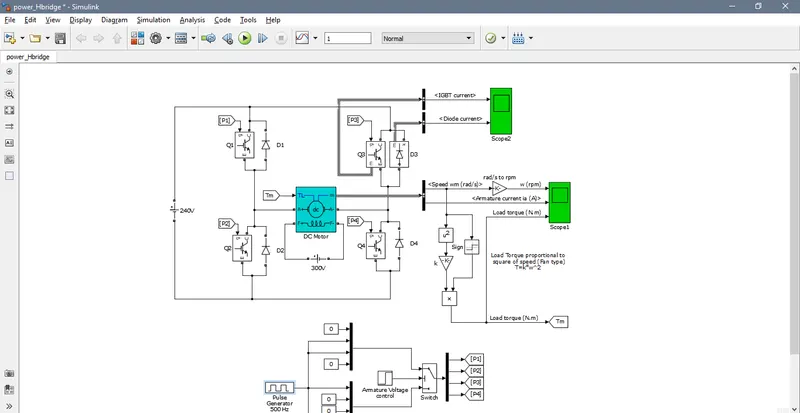
Run MATLAB demo ‘Speed control of a DC motor using BJT H-bridge’. Modify the model such that armature current doesn’t shoot up when motor changes direction from forward to reverse.
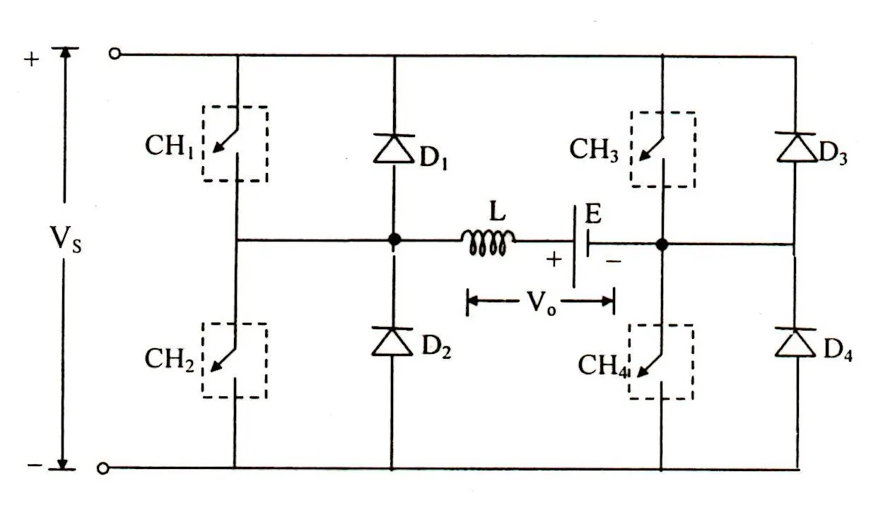
in this circute when switch 1 and 4 is closed the the motor run in one direction.and when the switch 2 and 3 are closed the the motor run in oposite direction .
Description
The Bipolar Junction Transistor (BJT) when used for power switching applications operates as an IGBT. When it is conducting (BJT operating in the saturated region) a forward voltage Vf is developed between collector and emitter (in the range of 1 V). Therefore the IGBT block can be used to model the BJT device.
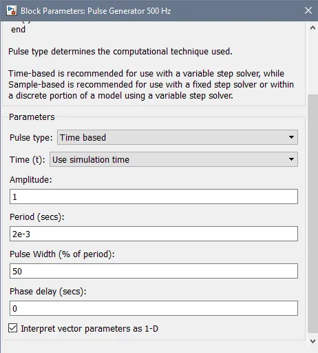
The IGBT block does not simulate the gate current controlling the BJT or IGBT. The switch is controlled by a simulink signal (1/0). The DC motor uses the preset model (5 HP 24V 1750 rpm). It simulates a fan type load (where Load torque is proportional to square of speed). The armature mean voltage can be varied from 0 to 240 V when the duty cycle (specified in the Pulse Generator block) is varied from 0 to 100%.
The H bridge consists of four BJT/Diode pairs (BJT simulated by IGBT models). Two transistors are switched simultaneously: Q1 and Q4 or Q2 and Q3. When Q1 and Q4 are fired, a positive voltage is applied to the motor and diodes D2-D3 operate as free-wheeling diodes when Q1 and Q3 are switched off. When Q2 and Q3 are fired, a negative voltage is applied to the motor and diodes D1-D4 operate as free-wheeling diodes when Q2 and Q3 are switched off.
Simulation
The motor starts in the positive direction with a duty cycle of 75% (mean DC voltage of 180V). At t= 0.5 sec. the armature voltage is suddenly reversed and the motor runs in the negative direction.
Scope1 shows motor speed, armature current and load torque and Scope2 shows currents flowing in BJT Q3 and diode D3.
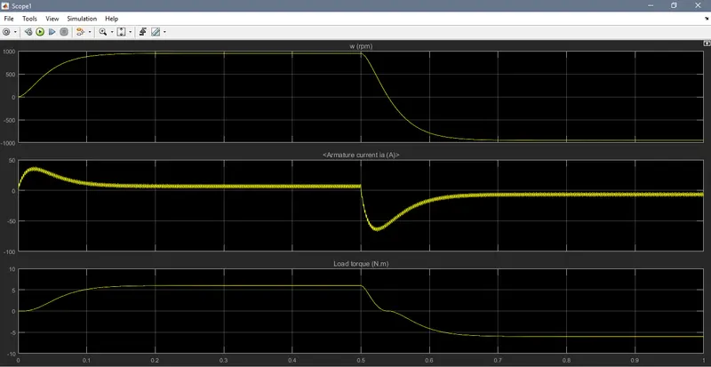
75% of duty cycle:
When the motor start positive direction with a duty cycle 75%.now the motor speed is 950.8rpm and also have high torque. at t is 0.5 sec the armature voltage is reversed and also motor run in negative direction.
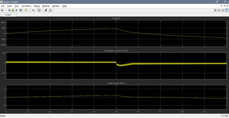
50% of duty cycle:
now the puls width is redused to 50%.so the motor speed also redused by 430rpm.the torque also redused visa-versa.
25% of duty cycle :
now the puls width is redused to 25%.so the motor speed also redused by 93rpm.the torque also redused visa-versa.
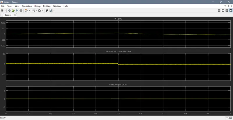
now the armature current does not shoot up when we change the motor direction forward to reverse.
2)
Refer to help section of ‘The Four-Quadrant Chopper DC Drive (DC7) block’. Compare it with H-bridge model.
The Four-Quadrant Chopper DC Drive (DC7) block represents a four-quadrant, DC-supplied, chopper (or DC-DC PWM converter) drive for DC motors. This drive features closed-loop speed control with four-quadrant operation. The speed control loop outputs the reference armature current of the machine.
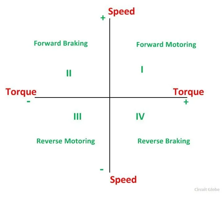
In the I quadrant power developed is positive and the machine is working as a motor supplying mechanical energy. The I (first) quadrant operation is called Forward Motoring. II (second) quadrant operation is known as Braking. In this quadrant, the direction of rotation is positive, and the torque is negative, and thus, the machine operates as a generator developing a negative torque, which opposes the motion.
The kinetic energy of the rotating parts is available as electrical energy which may be supplied back to the mains. In dynamic braking, the energy is dissipated in the resistance. The III (third) quadrant operation is known as the reverse motoring. The motor works, in the reverse direction. Both the speed and the torque have negative values while the power is positive.
In the IV (fourth) quadrant, the torque is positive, and the speed is negative. This quadrant corresponds to the braking in the reverse motoring mode.
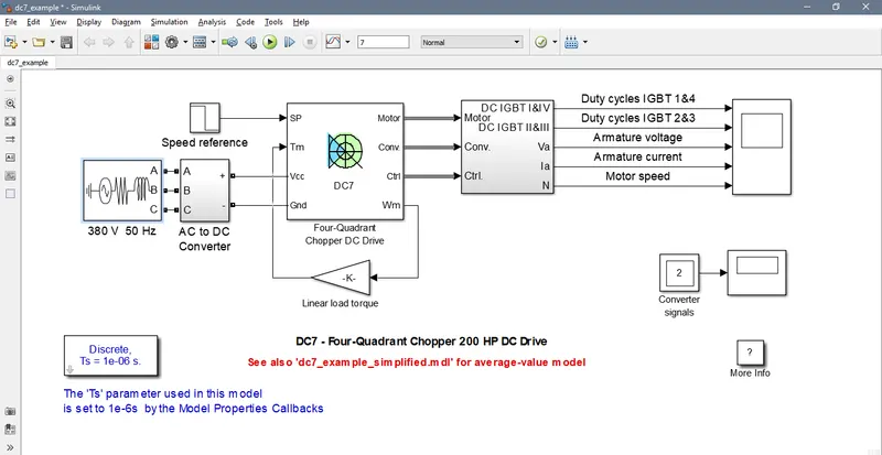
Before starting the simulation, set the initial bus voltage to 515 V via the GUI block ('Initial States Setting' button and 'Cbus' variable).
Start the simulation. You can observe the motor armature voltage and current, the four IGBT pulses and the motor speed on the scope. The current and speed references are also shown.
The motor is coupled to a linear load, which means that the mechanical torque of the load is proportional to the speed.
The speed reference is set at 500 rpm at t = 0 s. Observe that the motor speed follows the reference ramp accurately (+400 rpm/s) and reaches steady state around t = 1.3 s.
The armature current follows the current reference very well, with fast response time and small ripples. Notice that the current ripple frequency is 5 kHz.
At t = 2 s, speed reference drops to -1184 rpm. The current reference decreases to reduce the electromagnetic torque and causes the motor to decelerate with the help of the load torque.
At t = 2.2 s, the current reverses in order to produce a braking electromagnetic torque (dynamic braking mode). This causes the DC bus voltage to increase.
At t = 3.25 s, the motor reaches 0 rpm and the load torque reverses and becomes negative. The negative current now produces an accelerating electromagnetic torque to allow the motor to follow the negative speed ramp (-400 rpm/s). At t = 6.3 s, the speed reaches -1184 rpm and stabilizes around its reference.
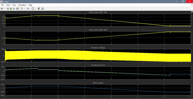
The Four-Quadrant Chopper DC Drive (DC7) block WITH h bridge
In four quadrant chopper DC drive distributes required current supply for each sector and it consist of four quadrants Regenerative Braking, Reverse Motoring and Reverse Regenerative Braking. whereas H-bridge supplies an irregular causes voltage fluctuation in armature current. It consist of two operations they are Forward motoring, reverse In modern battery charger for electrical vehicles, H-bridge circuits are used, A four-quadrant operation is required applications.
The efficiency is high in chopper compare with H-bridge, and maintenance is less than H-bridge.
In Robotics Technology, H-bridge circuits are used, Some other applications of four quadrant operation is engine The regenerative braking is not possible in H-bridge while in chopper it is possible.
The most important application of the H•Bridge circuit as the motor driver circuit. H-bridge circuits can be placed in chopper is lightweight in nature,
In H-bridge we need to change polarity whik turns into opposite direction to control the motor whereas in chopper one signal under control of another.
3)
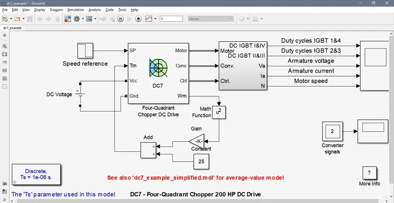
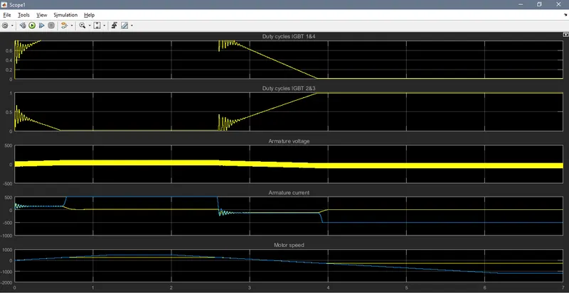
Make a suitable EV model using DC7 block and make result report.
It was a default model of DC7 block.here we have to do some changes.
- first we can change to DC source
- and delete the linear torque and create a new torque speed equation.
- if you want you have to insert a own drive cycle ,otherwise use default mode.
DC voltage: 200 voltage is given
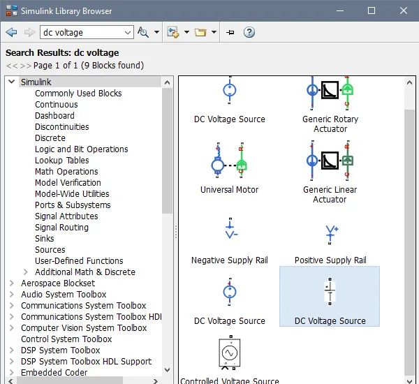
torque speed equation:
Tm=24.7+0.0051w^2
a)
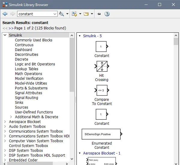
24.7 is a constant .so we have to use constant block and put your constant value.
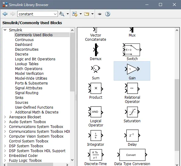
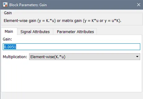
b) after we have to use gain block for 0.0051 .
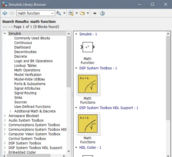
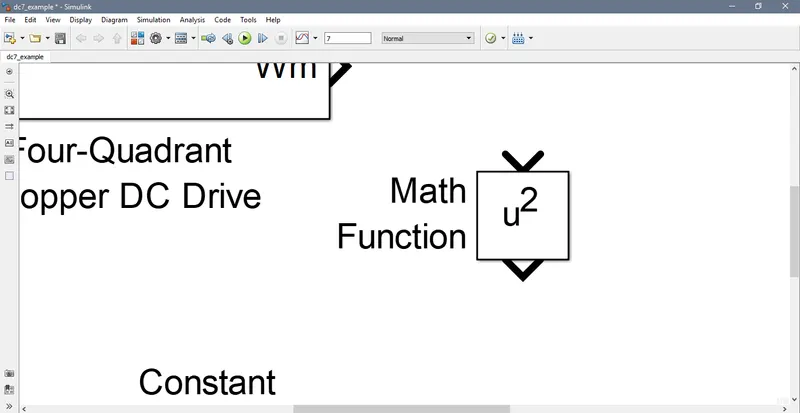
c) and finally we have to multyply with math function
close the model with Tm.
Result:
4)
- Explain in a brief about operation of BLDC motor.
A brushless DC electric motor (BLDC motor or BL motor), also known as electronically commutated motor (ECM or EC motor) and synchronous DC motors, are synchronous motors powered by direct current (DC) electricity via an inverter or switching power supply which produces electricity in the form of alternating current (AC) to drive each phase of the motor via a closed loop controller. The controller provides pulses of current to the motor windings that control the speed and torque of the motor. This control system replaces the commutator (brushes) used in many conventional electric motors.
The construction of a brushless motor system is typically similar to a permanent magnet synchronous motor (PMSM), but can also be a switched reluctance motor, or an induction (asynchronous) motor. They may also use neodymium magnets and be outrunners (the stator is surrounded by the rotor), inrunners (the rotor is surrounded by the stator), or axial (the rotor and stator are flat and parallel).[1]
The advantages of a brushless motor over brushed motors are high power-to-weight ratio, high speed, electronic control, and low maintenance. Brushless motors find applications in such places as computer peripherals (disk drives, printers), hand-held power tools, and vehicles ranging from model aircraft to automobiles. In modern washing machines, brushless DC motors have allowed replacement of rubber belts and gearboxes by a direct-drive design.
BLDC motor advantages:
Brushless motors offer several advantages over brushed DC motors, including high torque to weight ratio, more torque per watt (increased efficiency), increased reliability, reduced noise, longer lifetime (no brush and commutator erosion), elimination of ionizing sparks from the commutator, and an overall reduction of ...
BLDC motor disadvantages:
They are also compact in size and provides high torque with better speed control and efficiency. On the other hand, it also has a few disadvantages like higher cost, resonance issue, and complex wiring setup due to the involvement of electronic control.