Week-7 Challenge: DC Motor Control
Aim:-
- Run MATLAB demo ‘Speed control of a DC motor using BJT H-bridge’. Modify the model such that armature current doesn’t shoot up when the motor changes direction from forward to reverse.
- Refer to the help section of ‘The Four-Quadrant Chopper DC Drive (DC7) block’. Compare it with the H-bridge model.
- Make a suitable EV model using a DC7 block and make a result report.
- Explain in a brief about operation of BLDC motor.
Study 1:-To Run MATLAB demo ‘Speed control of a DC motor using BJT H-bridge’. Modify the model such that armature current doesn’t shoot up when the motor changes direction from forward to reverse.
H-bridge:
An H-bridge is a simple circuit that lets you control a DC motor to go backward or forward.
The H-Bridge circuit:-
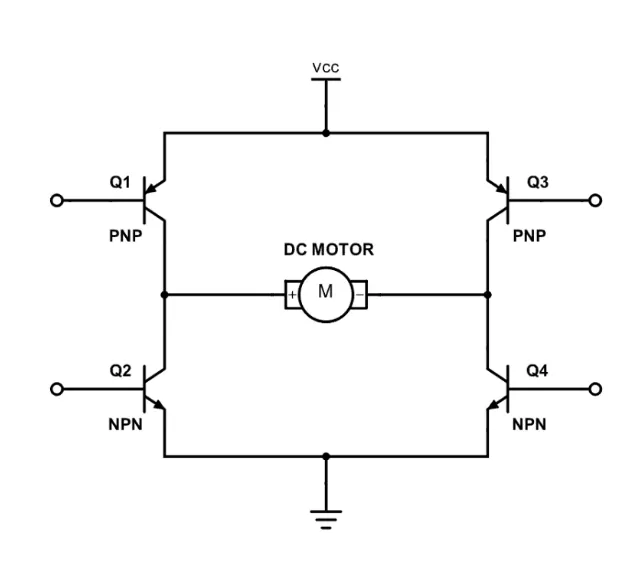
H-Bridge concept
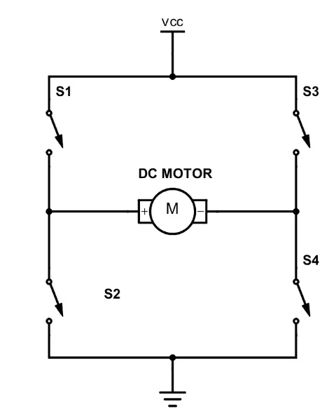
A DC motor turns either backward or forward, depending on how to connect the plus and the minus signs.
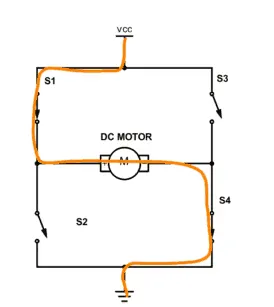
If we switch off 1 and 4, we have plus connected to the left side of the motor and minus to the other side. And the motor will start turning in one direction.
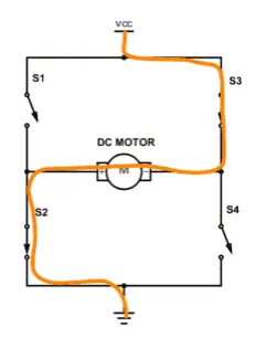
If we switch off 2 and 3, we have plus connected to the right side and minus to the left side. And the motor turns in the opposite direction.
Now opening H bridge in Matlab by pressing in the help section Power-H Bridge Command window we get the following Simulink Model:-
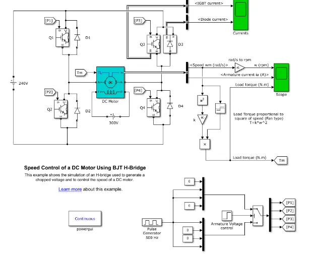
The Explanation of Simulation Model:-
- It consists of 4 IGBTS
- At a time 2 transistors will be switched on and off simultaneously.
- Q1,Q2,Q3,Q4 are Bipolar Transistors.
- D1,D2,D3,D4 are freewheeling diodes
When Q1 and Q4 are fired, a positive voltage is applied to the motor and diodes D2-D3 operate as free-wheeling diodes when Q1 and Q4 are switched off. (Forward Motoring)
When Q2 and Q3 are fired, a negative voltage is applied to the motor and diodes D1-D4 operate as free-wheeling diodes when Q2 and Q3 are switched off. (Reverse Motoring)
The pulse generator is connected to give an output to the forms of motor i.e which IGBT will turn ON. The circuit is connected to a 240 V DC supply and the motor power with a supply of 300 V supply.
Now for the Output shown below is the inbuilt value of Pulse width is 75%
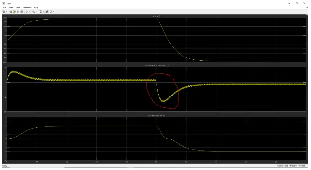
The red circle says that the peak in the current when the mode is shifted from forward to reverse condition from the above parameters.The parameters of the Pulse Generator are shown below
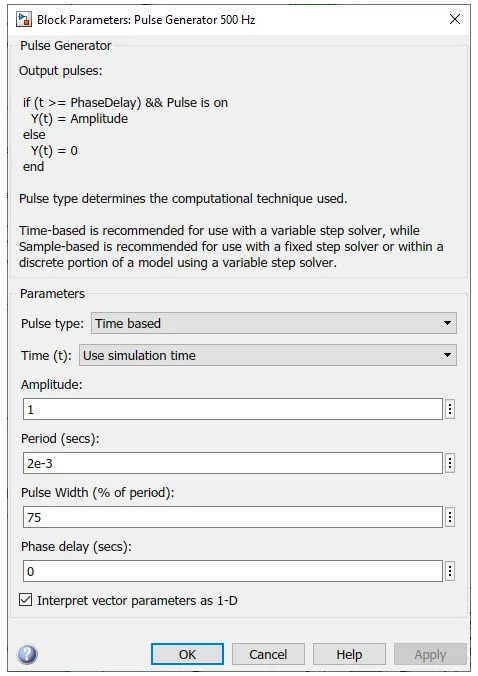
The above figure says that the Dc = 75% where average voltage of 180 V and Frequency=50HZ.By changing the pulse ratio and Dc we try to reduce this current by trial and error method.
We get the following Correct Output when we change the pulse width value = 30%
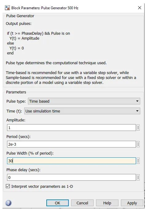
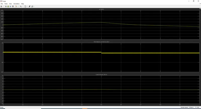
By reducing the amount of voltage entering we can control the Armature Current value.The Output is Shown below.
Study 3:-
Make a suitable EV model using DC7 block and make a result report.
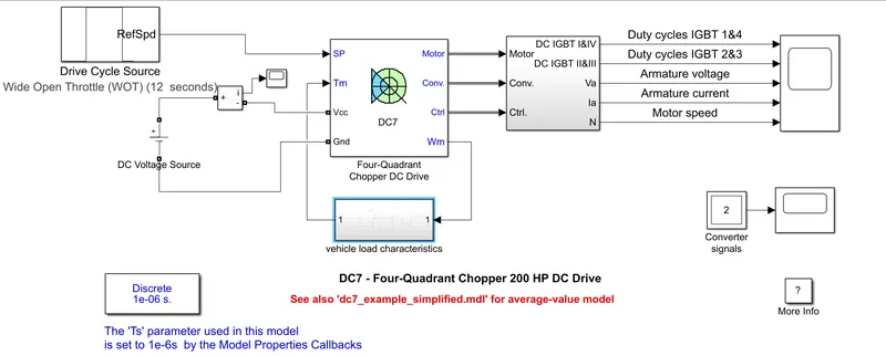
The DC7 block model has to be modified inorder to simulate the EV model.
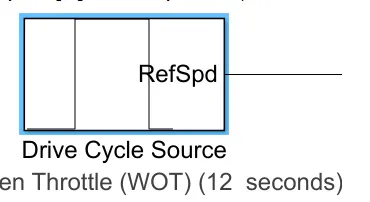
Drive cycle:-
By changing the Drive cycle block parameters values
Vehicle Load Characteristics:-
Linear Load Torque block is replaced with Subsystem Model according to the load Characteristics.
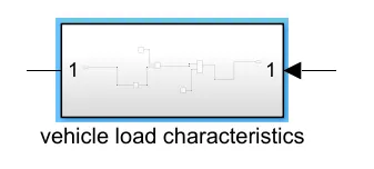
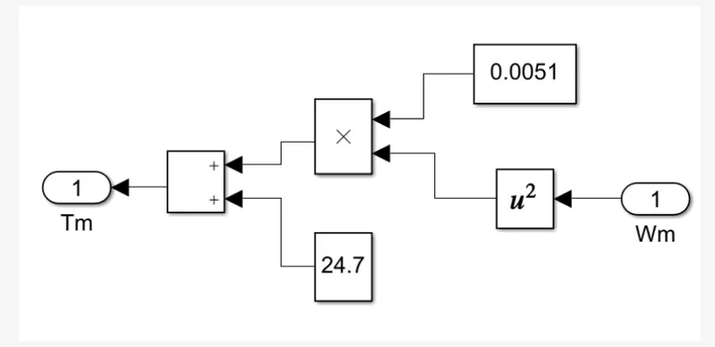
The above shown is an Subsystem
`T = 24.7+0.0051w^2`
The above equation is created in the simulink model as
Electric Vehicle final model:-
Drive Cycle:-
A driving cycle is a set of values, generally, it would be a velocity vs time graph of a vehicle.
Driving cycles can be classified into 2 Types.They are
- Model Driving Cycles and
- Transient Driving Cycles.
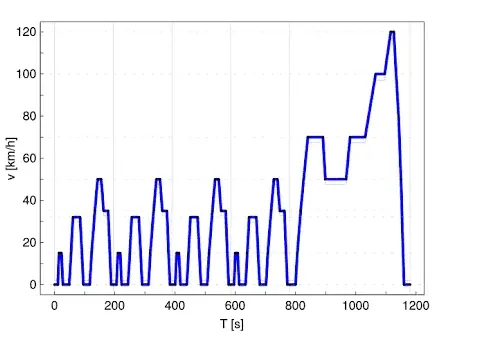
Model Driving Cycle
The model driving cycle comprises constant speed and does not represent a real driving pattern of a vehicle.
The Example for Model Driving Cycle is New European Driving Cycle (NEDC)
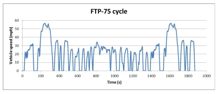
Transient Driving Cycle
The transient driving cycle represents an actual pattern of a vehicle which contains acceleration, deceleration, constant speed, etc.
The Example for Transient Driving Cycle is Federal Test Procedure (FTP 75)
Four Quadrant Chopper Dc Drive:-
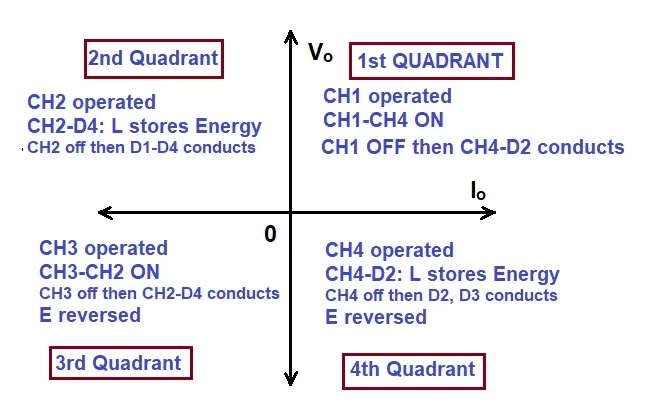
The Four Quadrant Chopper consists of four types.They are
-
First Quadrant Operation:
-
Second Quadrant Operation:
-
Third Quadrant Operation:
-
Fourth Quadrant Operation:
First Quadrant Operation:-
For the first quadrant operation, CH4 is ON, CH3 is OFF and CH1 is operated. When both CH1 & CH4 are ON simultaneously, the load gets directly connected to the source and hence the output voltage becomes equal to the source voltage. This says that vo = vs. It may be known that the load current flows from source to load.
When CH1 is switched OFF, the load current free wheels through CH4 and D2. During this period, the load voltage and current remains positive.
Thus, both the output voltage vs load current io are positive and hence, the operation of the chopper is in the first quadrant.It operates as the Step down Chopper.
Second Quadrant Operation:
In the second quadrant operation, CH2 is operated while keeping the CH1, CH3 & CH4 OFF. When CH2 is ON, the DC source in the load drives current through CH2, D4, E and L. Inductor L stores energy during the On period of CH2.
When CH2 is turned OFF, current is fed back to the source through D1, D4. It should be noted at this point that (E+Ldi/dt) is more than the source voltage Vs. As load voltage Vo is positive and Io is negative, it is the second quadrant operation of the chopper. For second quadrant operation, load must contain emf E as shown in the circuit diagram. In the second quadrant, configuration operates as a step-up chopper.
Third Quadrant Operation:-
In the third quadrant operation, CH1 is kept off, CH2 is kept ON and CH3 is operated. When CH3 is ON, load gets connected to source and hence load voltage is equal to source voltage.Now, when CH3 is turned OFF, the negative load current free wheels through the CH2 and D4. In this manner, vo and io both are negative. Hence, the chopper operates in the third quadrant.
Fourth Quadrant Operation:
In the fourth quadrant operation, CH4 is operated while keeping CH1, CH2 and CH3 OFF. When CH4 is turned ON, positive current flows through CH4, D2, L and E. Inductance L stores energy during the time CH4 is ON. When CH4 is made OFF, current is fed back to the source through diodes D2, D3.. This leads to chopper operation in the fourth quadrant. The chopper acts as a step-up chopper.
Plot the Result:-

The above model of 4 quadrant dc motor.The above graph shows that
- From the duty cycle IGBT 1&4 and IGBT 2&3 states that initially step increment and decrement of the triggering points takes place.
- In the Armature Voltage if the triggering point increases in the same way voltage also increases.
- In the Armature current will be same as step increment and decrement
- At the motor speed it matches with the duty cycle and will be in constant condition.
Study 4:-Explain in a brief about operation of BLDC motor.
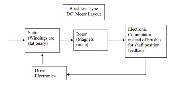
A Brushless DC Motor is the same as a Brushed DC Motor , a BLDC doesn’t use brushes for commutation but rather they are electronically commutated. In conventional Brushed DC Motors, the brushes are used to transmit the power to the rotor as they turn in a fixed magnetic field.
The BLDC motor layout is shown below:-
Construction of BLDC Motor:-
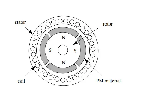
The BLDC Motor is a type of synchronous motor in the sense that the magnetic field generated by the stator and the rotor revolve at the same frequency.BLDC motors also have a rotor and a stator.
Brushless Motors are available in three configurations:
- single phase,
- two phase and
- three phase.( the three phase BLDC is the most common one)
The following image shows a BLDC Motor:-
Stator:-
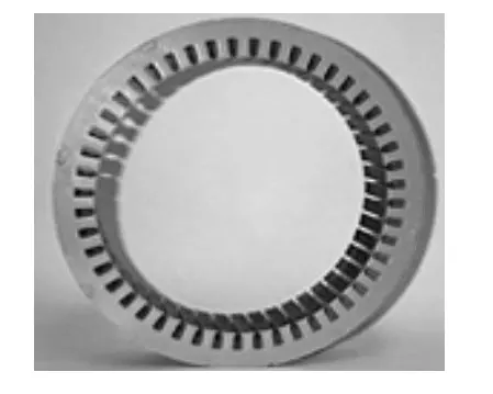
The structure of the stator of a BLDC Motor is similar to that of an induction motor. It is made up of stacked steel laminations with axially cut slots for winding. The windings in BLDC are slightly different than that of the traditional induction motor.
Rotor:-
The Rotor part of the BLDC Motor is made up of permanent magnets and alloy of Neodymium, Ferrite and Boron.Based on the application, the number of poles can vary between two and eight with North (N) and South (S) poles placed alternately.
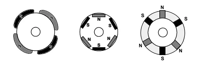
- In the first case, the magnets are placed on the outer periphery of the rotor.
- The second configuration is called a magnetic-embedded rotor, where rectangular permanent magnets are embedded into the core of the rotor.
- In the third case, the magnets are inserted into the iron core of the rotor.
Working Of a BLDC Motor:-
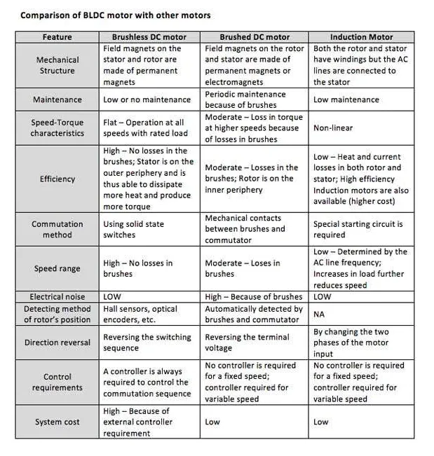
The principle for the working of BLDC motors are the same as for a brushed DC motor. In the case of a brushed DC motor, feedback is implemented using a mechanical commutator and brushes. Within the BLDC motor, it is achieved using multiple feedback sensors. In BLDC motors we mostly use a Hall-effect sensor, whenever rotor magnetic poles pass near the hall sensor, they generate a HIGH or LOW-level signal, which can be used to determine the position of the shaft. If the direction of the magnetic field is reversed, the voltage developed will reverse too.
Advantages of BLDC Motors:-
- No wear and tear (due to absence of brushes)
- High efficiency
- Better speed vs torque characteristics
- Long life
- Less noise or noiseless operation
- Significantly higher RPM
Applications of BLDC Motor:-
- Single speed applications
- Adjustable speed applications
- Position control
- Low noise applications
- High speed applications
Conclusion:-
By reducing the duty cycle we can reduce the armature current.
Dc7 block is used to create an electric vehicle.