Week-7 Challenge: DC Motor Control
1)
Run MATLAB demo ‘Speed control of a DC motor using BJT H-bridge’. Modify the model such that armature current doesn’t shoot up when motor changes direction from forward to reverse.
A bipolar junction transistor (BJT) is a type of transistor that uses both electrons and holes as charge carriers. Unipolar transistors, such as field-effect transistor, use only one kind of charge carrier. A bipolar transistor allows a small current injected at one of its terminals to control a much larger current flowing between two other terminals, making the device capable of amplification or switching.BJTs use two junctions between two semiconductor types, n-type and p-type, which are regions in a single crystal of material.
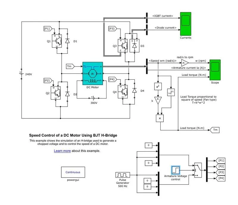
Armature Voltage Control :
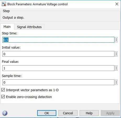
- The step-time for the simulation is taken as 0.5 seconds.
- That means each iteration will be performed for a time of 0.5 seconds.
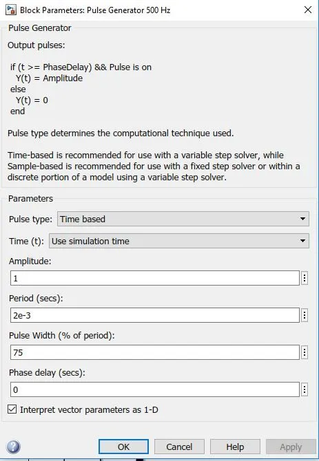
- The magnitude of the pulse generator is 500 Hz.
- The amplitude is taken as 1.
- No phase delay is given.
- The pulse width is 75%.
Results :
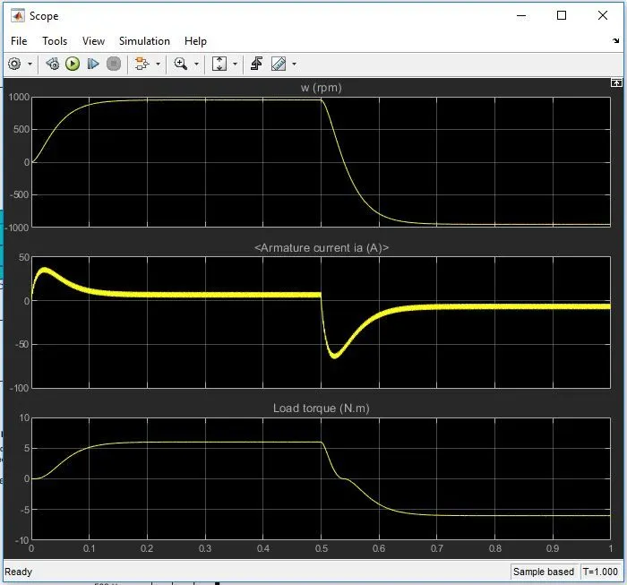
Plot 1 :
At starting when the motor is starting the torque needed is more, hence revolution per minute of the motor is increasing as a result of which the plot starts from zero and shows an increase in variation.Then the motor runs for the required amount of time, and when the voltage is down the rpm falls down from around 900 rpm to a negative value. and then the plot gets constant.
Plot 2 :
When the motor is starting the the current required is more as a result the graph shows a increase variation at the starting.When the time reaches 0.5 seconds, the armature current drops suddenly in a drastic way.And at the same time the armature current shoots up suddenly at 0.5 seconds, which is not desired.We have to make changes in such a way that the armature current does not shoots up and remains constant through out.The value of the current goes to a value of negative approximately -70 amperes.
Plot 3 :
At the starting of the motor the load required increases gradually and as a result the graph shows a increase variation with respect to time.Then with the fall of current and torque the load also decreases.The load is directly proportional to the current and the armature revolution.
Changes done :
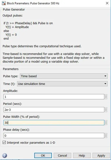
In the block parameters the pulse generator is of 500 Hz.The amplitude is defined as 1. The phase delay is given as Zero.The pulse width is taken as a value of 30
Results :
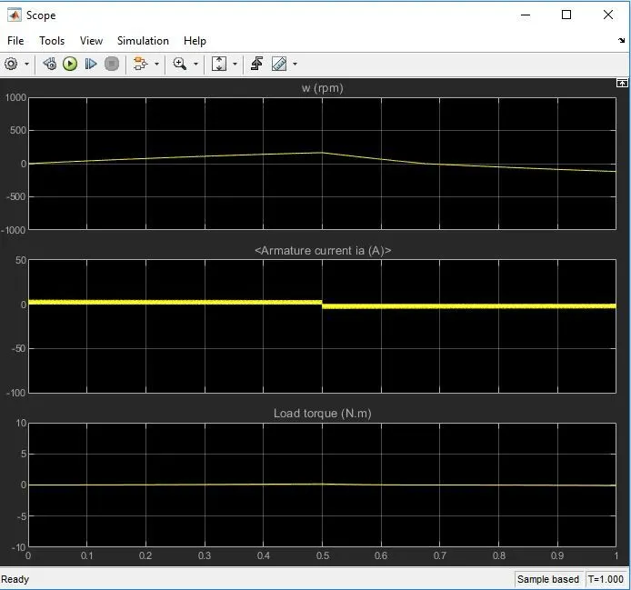
Explanation :
When we decrease the time period of the signal or the pulse generator, we can see that the starting of the motor is smooth without any hindrance.The speed of the motor increases linearly with respect to time, then at time period of 0.5 seconds it a dips very negligibly as a result the armature revolution also drops and after that the rpm remains constant.
Beacuse of the smooth revolution of the motor the current used by the motor is also less and and constant, as the speed is constant through out the armature current consumption is linear and constant.As a result of which the load required during the whole process of motor operation is constant through out.
2)
Refer to help section of ‘The Four-Quadrant Chopper DC Drive (DC7) block’. Compare it with H-bridge model.
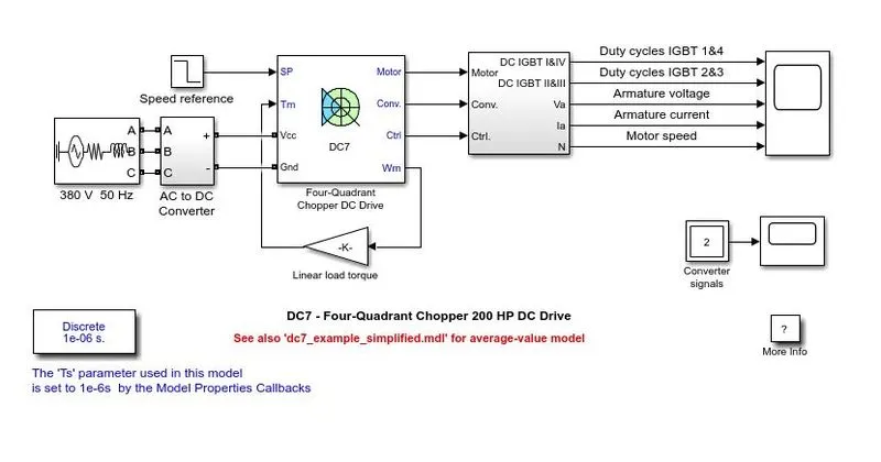
The 200 HP DC motor is separately excited with a constant 150 V DC field voltage source.The armature voltage is provided by an IGBT converter controlled by two PI regulators.The converter is fed by a 515 V DC bus obtained by rectification of a 380 V AC 50 Hz voltage source.In order to limit the DC bus voltage during dynamic braking mode, a braking chopper has been added between the diode rectifier and the DC7 block. The first regulator is a speed regulator, followed by a current regulator.
The speed regulator outputs the armature current reference (in p.u.) used by the current controller in order to obtain the electromagnetic torque needed to reach the desired speed.The speed reference change rate follows acceleration and deceleration ramps in order to avoid sudden reference changes that could cause armature over-current and destabilize the system.The current regulator controls the armature current by computing the appropriate duty ratios of the 5 kHz pulses of the four IGBT devices (Pulse Width Modulation).For proper system behaviour, the instantaneous pulse values of IGBT devices 1 and 4 are opposite to those of IGBT devices 2 and 3.
This generates the average armature voltage needed to obtain the desired armature current. In order to limit the amplitude of the current oscillations, a smoothing inductance is placed in series with the armature circuit.
Four-Quadrant Chopper can operates in all four modes (Forward Motoring,Forward Braking, Reverse Motoring and Reverse Braking), but H-bridge can operate only in two modes (Forward and Reverse).In Four-Quadrant Chopper Regenerative Braking is possible, but H-bridge Regenerative Braking is not possible.In Four-Quadrant Chopper Two PI regulator (Speed Regulator and Current Regulator) is used to obtain electromagnetic torque needed to reach the desired speed and control the armature current and stabilize the system, but in H-bridge model PI regulator is not used.H-bridge is a electronic circuit that switches the polarity of voltage applied to the load and Four-quadrant Chopper is electronic switch that is used to interupt one signal under the control of another.H-bridge circuit are often used in Robotics and other applications to allow dc motor to run forward and backward.Four-Quadrant Chopper circuit is used to refer numerous type of electronic sitching devices and circuits used in power control and signal applications.Four-Quadrant Chopper model gives better efficiency and high energy(power) storage than H-bridge model.
3)
Make a suitable EV model using DC7 block and make result report.
The armature voltage is provided by an IGBT converter controlled by two PI regulators. The converter is fed by a 515 V DC bus obtained by rectification of a 380 V AC 50 Hz voltage source.In order to limit the DC bus voltage during dynamic braking mode, a braking chopper has been added between the diode rectifier and the DC7 block.The first regulator is a speed regulator, followed by a current regulator.The speed regulator outputs the armature current reference (in p.u.) used by the current controller in order to obtain the electromagnetic torque needed to reach the desired speed.The speed reference change rate follows acceleration and deceleration ramps in order to avoid sudden reference changes that could cause armature over-current and destabilize the system.The current regulator controls the armature current by computing the appropriate duty ratios of the 5 kHz pulses of the four IGBT devices (Pulse Width Modulation).For proper system behavior, the instantaneous pulse values of IGBT devices 1 and 4 are opposite to those of IGBT devices 2 and 3.This generates the average armature voltage needed to obtain the desired armature current. In order to limit the amplitude of the current oscillations, a smoothing inductance is placed in series with the armature circuit.
How to model it for an Electric vehicle
- The energy source of an EV is a battery or fuel cell. Let’s take the case of a battery.
- So the model can be modified with an input of a battery from the Simulink Library Browser.
- You can take a generic battery model and configure it by referring to any datasheet sheet related to an EV vehicle battery model.
- Otherwise the easy option is to use a simple DC source as your energy source and give the appropriate voltage value for an EV. The scope results vary in both cases from each other
How to modify energy source :
You can take a generic battery model and configure it by referring to any datasheet sheet related to an EV vehicle battery model.
Otherwise the easy option is to use a simple DC source as your energy source and give the appropriate voltage value for an EV. The scope results vary in both cases from each other
You can prepare your own drive cycle data and import it to this model also.
Linear load torque block can be replaced with a subsystem model according to the load characteristics given by
Results :
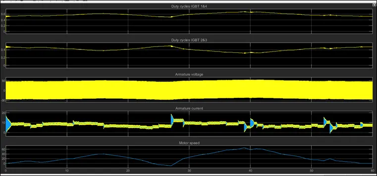
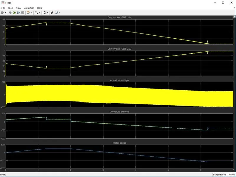
- The above figure shows Plots of Supply Voltage, Armature Current, IGBT duty Ratios & Motor Speed.
- Speed values are based on the Input Duty Cycles.
- Battery Voltage is capable enough to provide the required Armature Current throughout the Cycle.
- The Supply Voltage has been found Proportional to the demanding Load and Speed of the Motor.
- During deceleration after t=20s, a negative Armature Current can be observed which shows the Regenerative Braking where the Battery is being Charged.
- IGBT 1 & 4 are used for Positive Cycles and IGBT 2&3 for Negative Cycles.
- It can be observed that Duty Ratio of IGBT 1&4 is inversely proportional to IGBT 2&3.
- This duty ratios will control the Supply Voltage and in turn the Armature Current.