Week-7 Challenge: DC Motor Control
Aim:
* To Run a matlab model demo of "Speed control of a DC motor using BJT bridge, and to Modify the model such that armature current doesn’t shoot up when motor changes direction from forward to reverse.
* To model the ‘The Four-Quadrant Chopper DC Drive (DC7) block’, and to Compare it with H-bridge model.
* Make a suitable EV model using DC7 block and make result report.
i) Running a matlab model demo of "Speed control of a DC motor using BJT bridge, and to Modify the model:
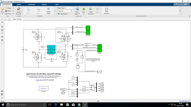
fig 1: The model of "Speed control of DC motor", In 1 second stoptime.
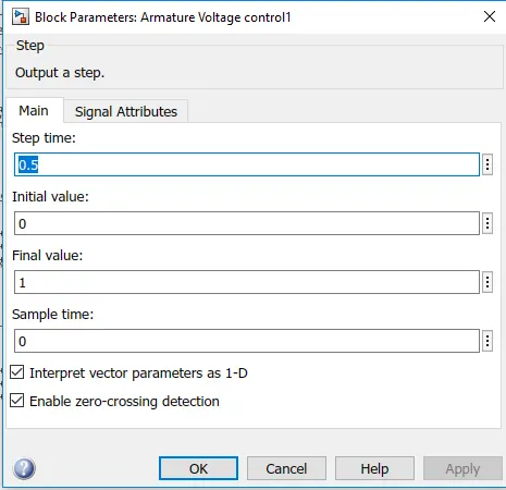
fig-2: setting the step time values in ARMATURE VOLTAGE CONTROL
* The step time of 0.5 seconds that determine the output value of this block for 0.5 seconds, and returns 1 as output value for the time period of 0.5-1 sec.
* The output of the step block is connected to the u2 port of the switch of the threshold of 0.5.
* For 0.5 seconds, the u3 port gets activated and for the rest of simulation, port u1 is activated.
* Hence, for 0.5 seconds, the switches Q1 and Q4 are getting activated. So, the positive flow occurs in DC motor.
* For the rest of 0.5 seconds, The switches Q2 and Q3 gets activated, So the negative flow occurs in DC motor.
* The positive flow indicates that the car moves in forward direction, whereas The negative flow indicates that the car moves in reverse direction.
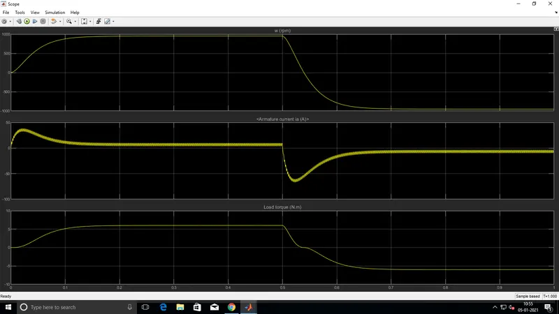
fig-3: The scope of the vehicle running.
* The initial stage in the graph showing the armature current, due to the excess power required to accelerate the vehicle.
* Once the vehicle obtains the specific speed, there will be no need of extra power, and the constant armature current is drawn from the battery.
* When the sudden reverse gear is applied, the current flow occurs at Q3 and Q2, and the vehicle working towards -1000 to +1000 rpm.
* The sudden reverse gear applied in the vehicle, which is in forward movement, gives rise to the armature current, which is greater than -50 Ampere.
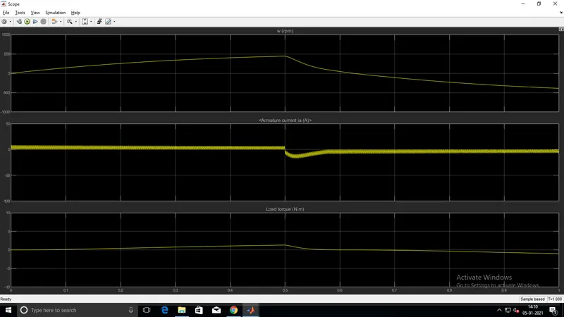
fig-4: The duty cycle ratio is changed into 50% in pulse generator block.
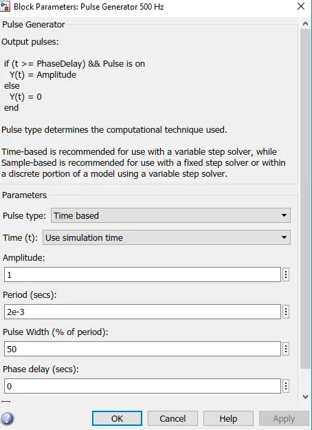
fig-5: setting the pulse ratio
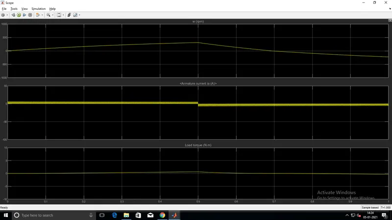
fig-6: The duty cycle ratio is changed into 40% in pulse generator block.
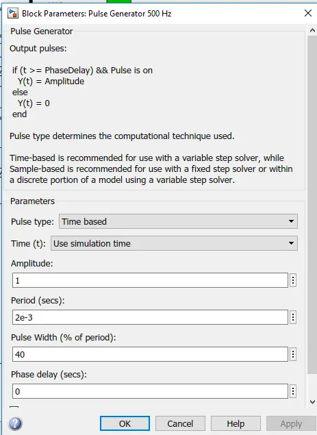
fig-7: setting the pulse ratio
2) Modelling the ‘The Four-Quadrant Chopper DC Drive (DC7) block’, and to Compare it with H-bridge model:
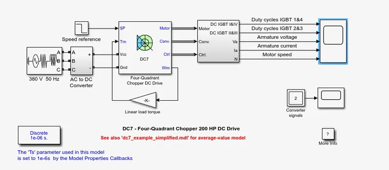
fig-8: Four quadrant DC chopper drive
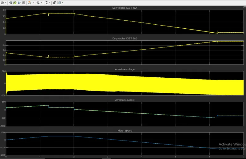
fig-9: Scope obtained from four quadrant DC chopper drive
* The chopper is used for converting fixed DC into variable DC
* A DC voltage source is used to drive motor in four quadrant chopper.
* A system consists of four choppers, used for controlling the speed of motor.
* IGBT is used to provide the current and voltage in armature.
* When Q1 and Q4 are fixed, positive voltage is applied and Q2 and Q3 are closed. Hence, the motor is driven in forwarddirection.
* When Q2 and Q3 are fixed, negative voltage is applied and Q1 and Q4 are closed. Hence, the motor is driven in reverse direction.
Differences:
* DC 4 quadrant is used in automobiles, while BJT is used in robotics.
* DC consists of PI current controller and BJT, PI is not present.
* The direction of motor is reverse biased on speed reference in DC7, but in BJT, duty cycle is used.
3) Making a suitable EV model using DC7 block and result report.
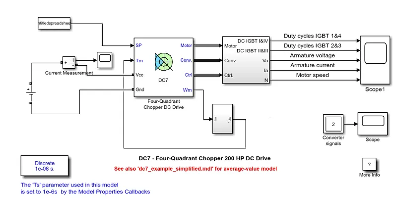
fig-10: Modified DC7 chopper into EV model
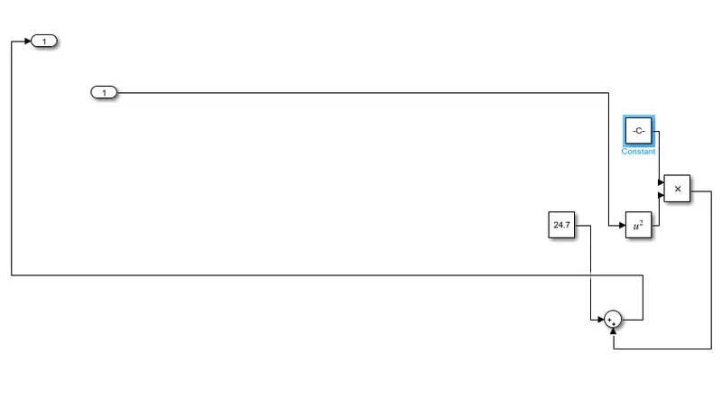
Fig-11: The subsystem for calculating TORQUE EQUATION.
* The DC block is modified into EV model using some addition of blocks.
* The speed reference is replaced with FROM WORKSPACE.
* AC source is replaced with DC voltage source, The CURRENT MEASUREMENT is added along with the SCOPE.
* A new subsystem is created with the TORQUE EQUATION.
* The Torque equation is T = 24.7 + 0.0051w2
* Hence the Graph is then generated.
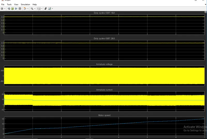
fig-12: Graph shown in the scope.
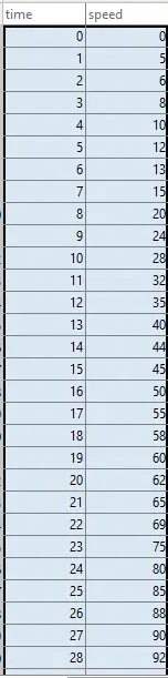
fig-13: Values for drive cycle, that is to be stored in FROM WORKSPACE.
* From the values of IGBT, The variation in voltage and current takes place according to the speed of the motor.
Conclusion:
Running a matlab model demo of "Speed control of a DC motor using BJT bridge, Modelling the ‘The Four-Quadrant Chopper DC Drive (DC7) block’, and Comparing it with H-bridge model, Making a suitable EV model using DC7 block, has been done and analysed using SIMULINK and MATLAB software.