Week 7 Challenge - Assembly Workbench
ASSEMBLY WORKBENCH
Objective:
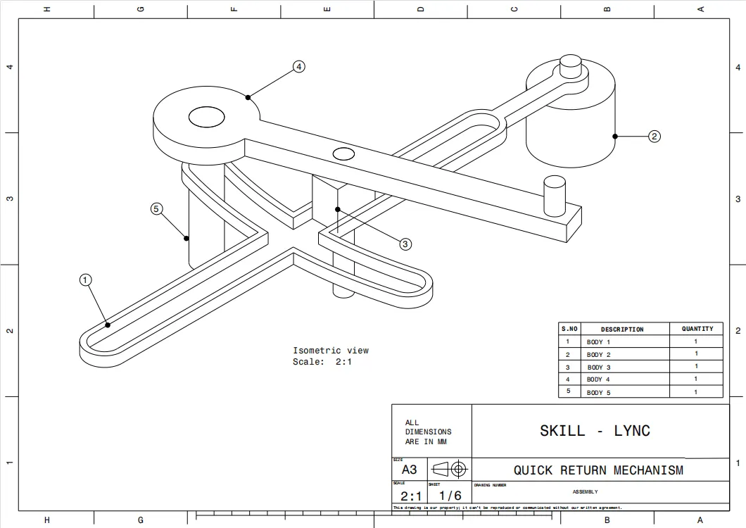
To create an individual part files of a given 2D drawing and then create a complete assembly of those part files in assembly workbench. After creating assembly by using drafting workbench to create a 2D drawing of the assembly and individual part files.
Introduction:
- Assembly modeling is a technology and process of using CAD and productive visualization software to design components of a product.
- Assemblies are 3D files that contain multiple parts or other assemblies. In the assemblies you can connect parts together with mates or constraints to buildup a 3D model of an entire system.
Drawing 1:
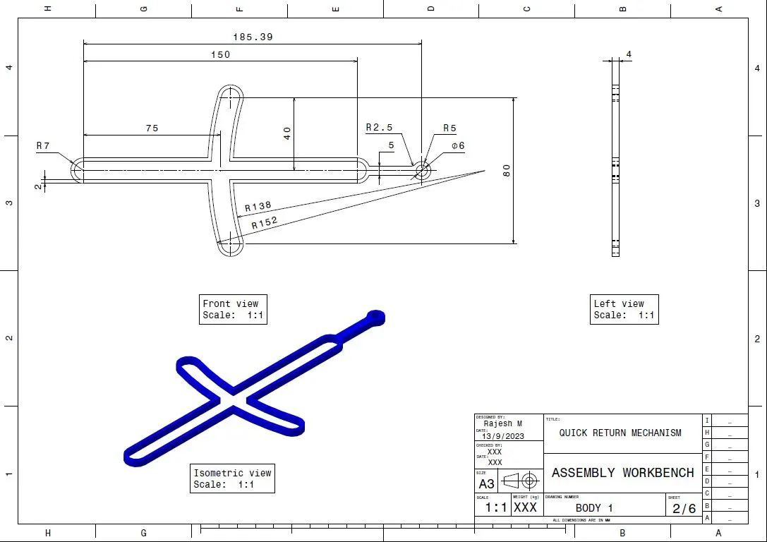
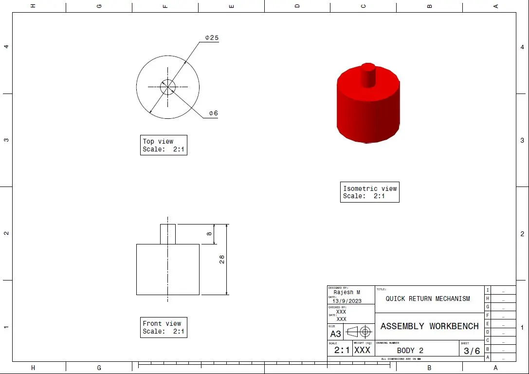
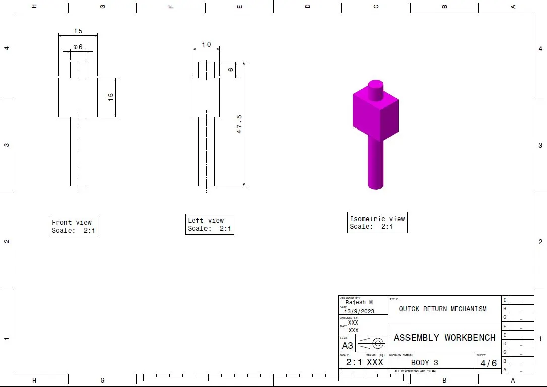
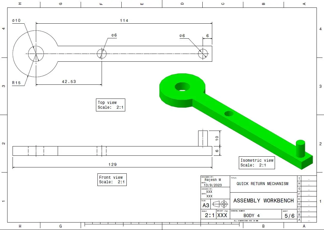
Given drawing: Quick Return Mechanism
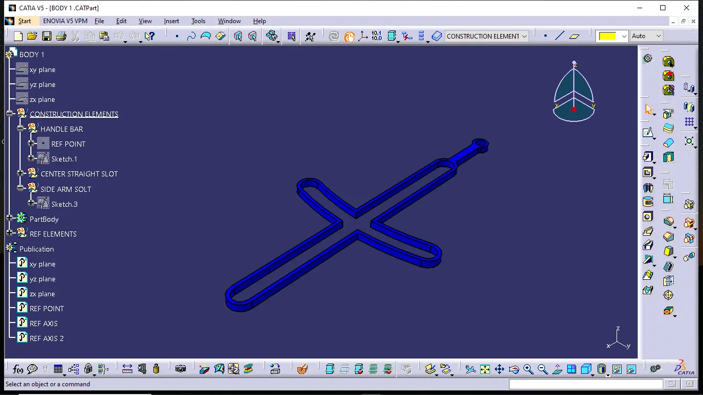
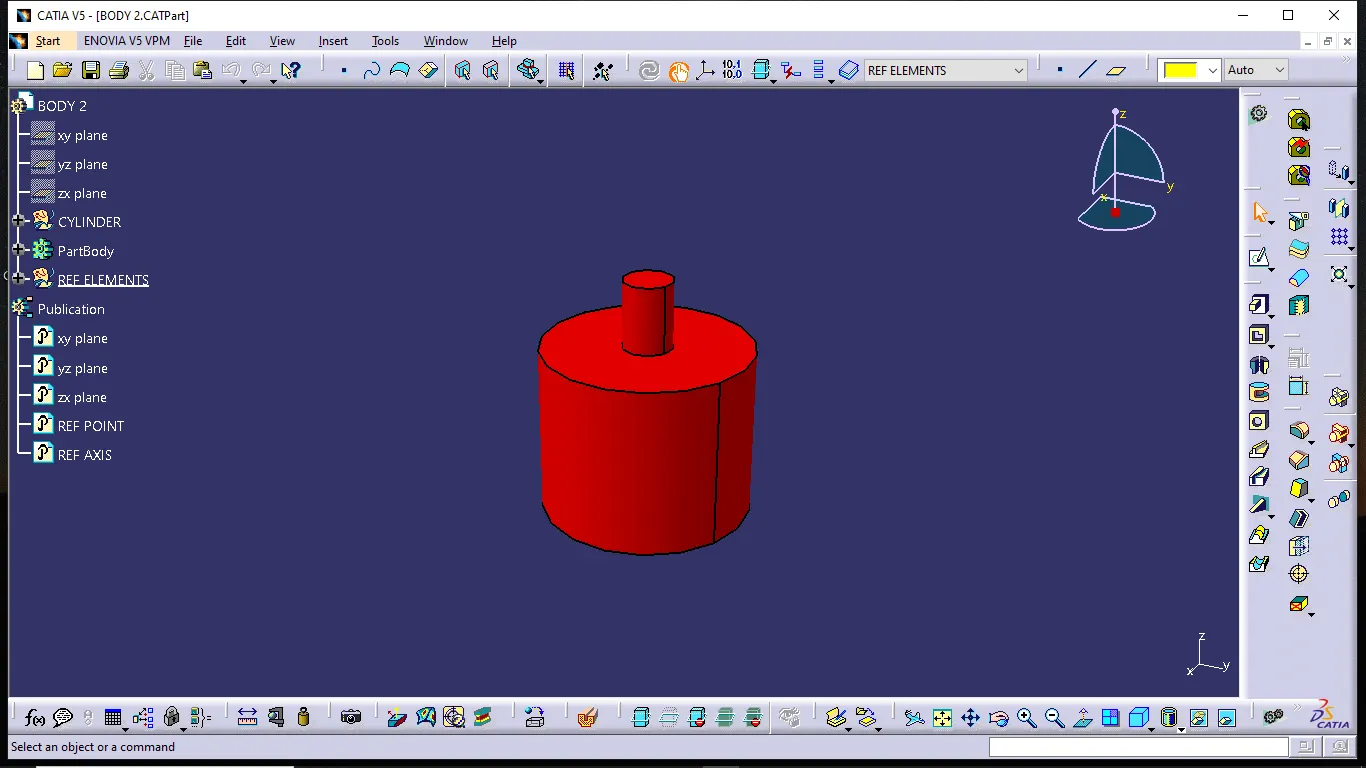
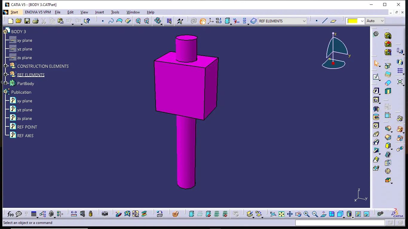
Creating Part files:
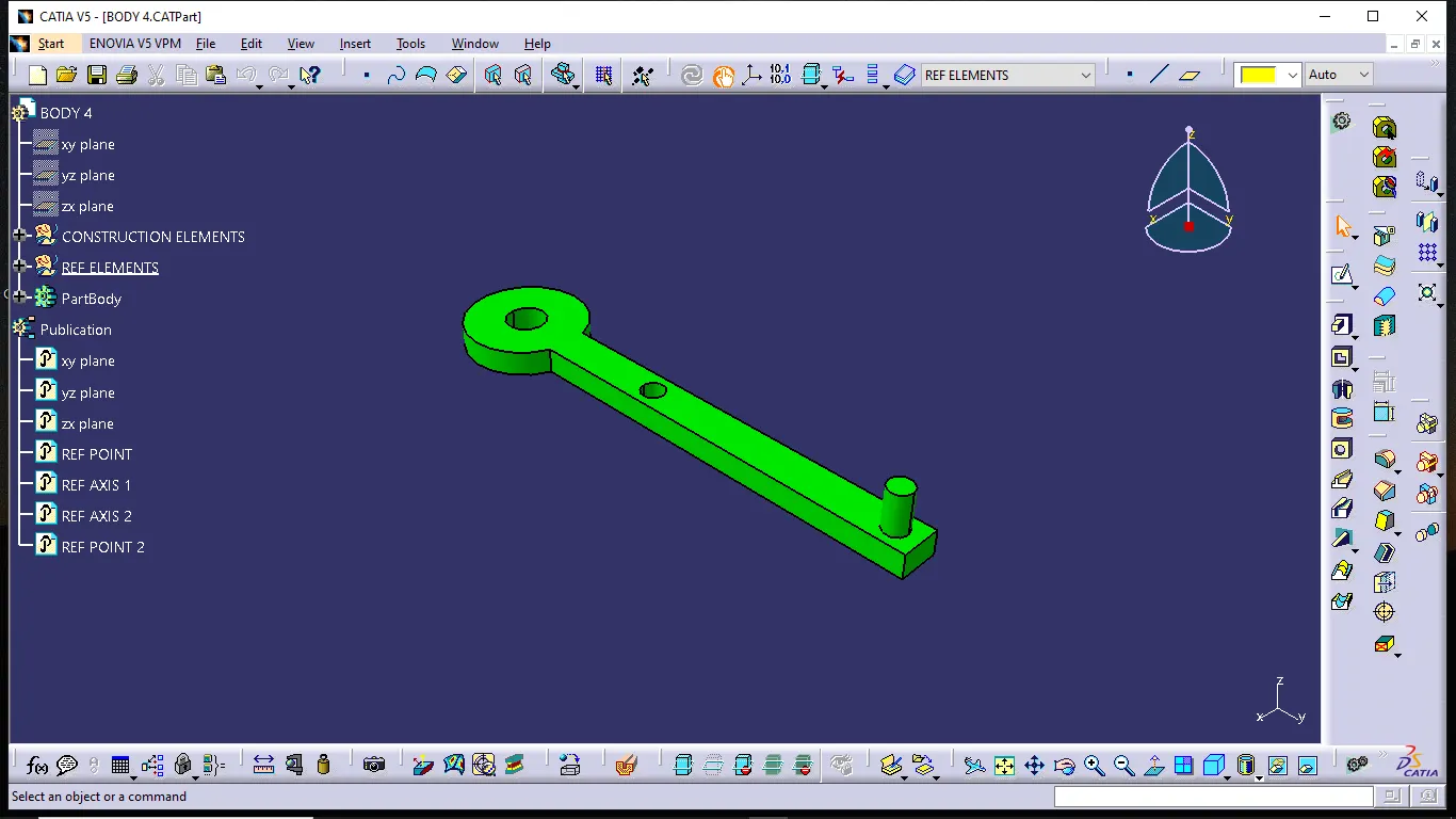
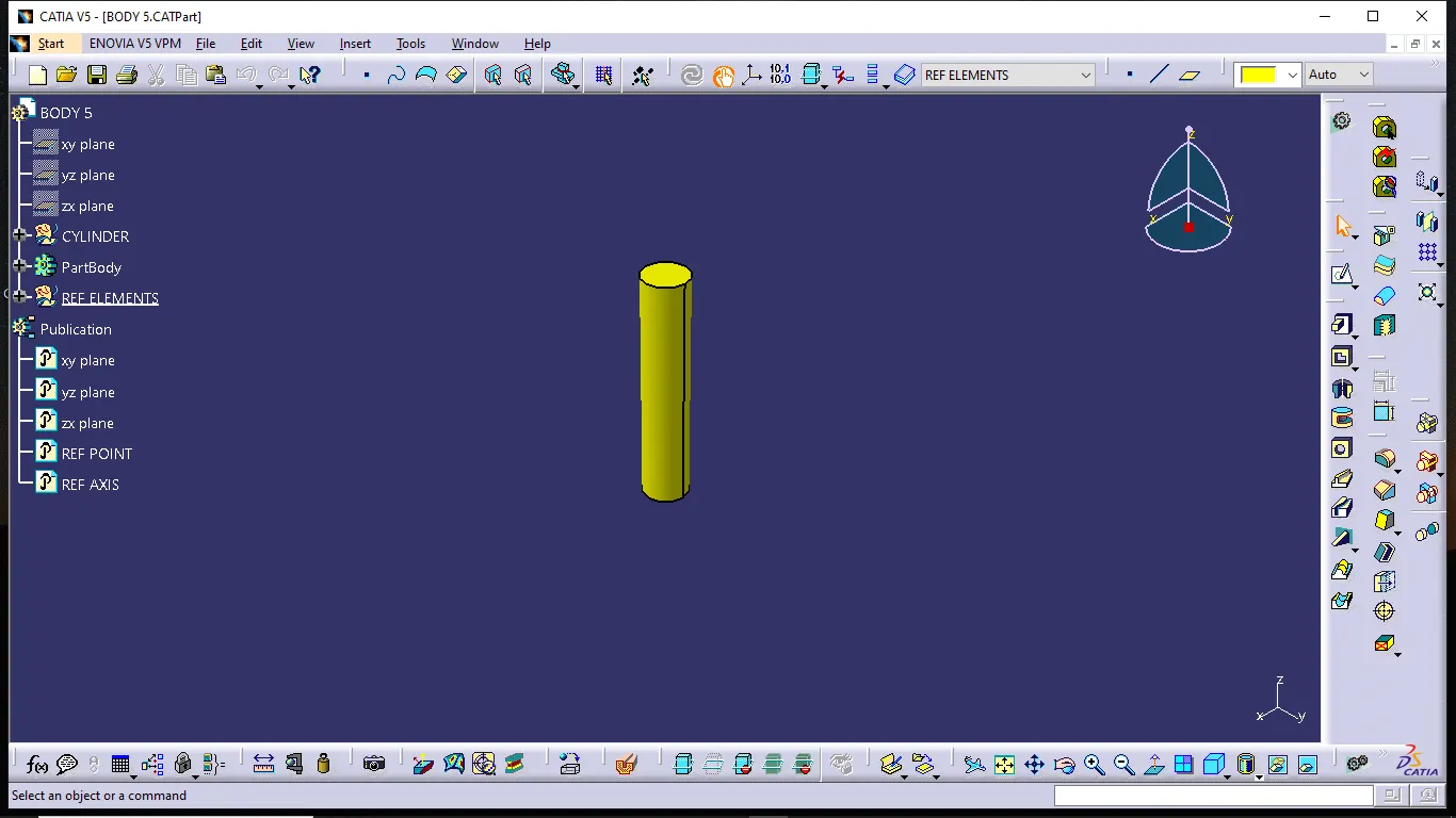
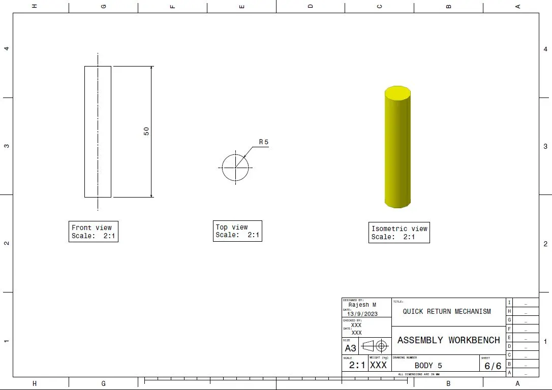
From the given individual part file model created by using the part workbench.
Assembly Workbench:
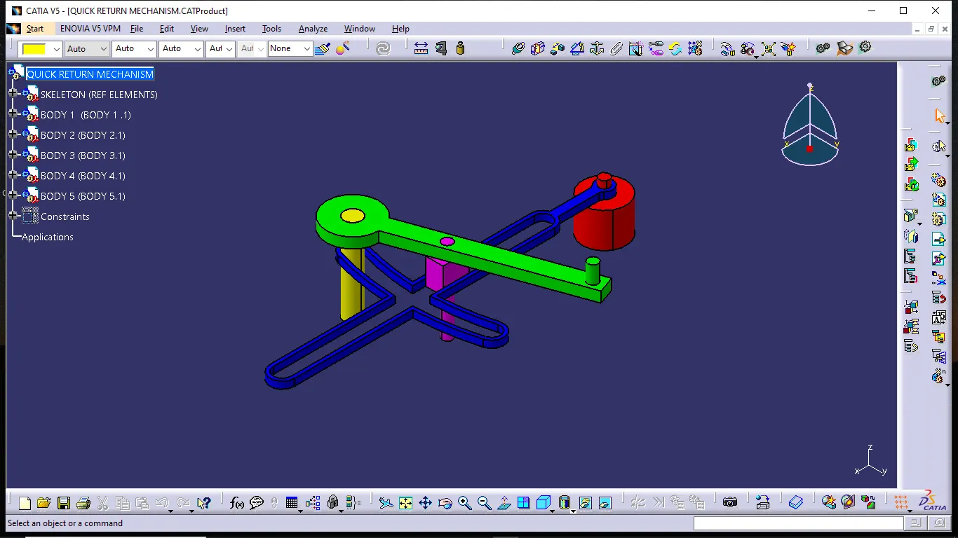
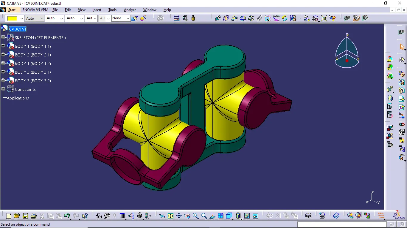
- In the assembly workbench we have to create a new CATproduct file and insert all individual part files inside the assembly.
- After inserting all part files, we have to create a reference plane and a point then named into skeleton. In the assembly using a fix constraint to fix the skeleton for assemble all CATpart together.
- Now create a reference plane, axis and point for all CATpart and publish the all the reference elements.
- In assembly constraints are used to make the CATpart together by using the coincidence, offset tools.
Drafting:
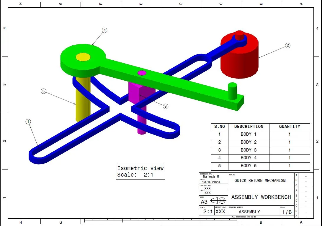
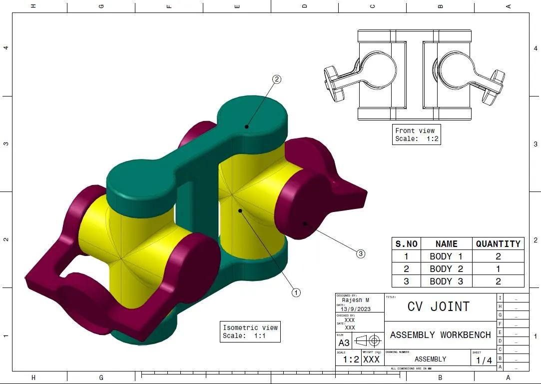
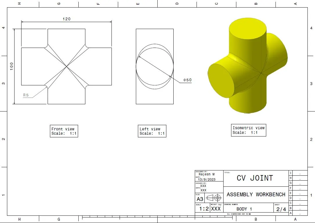
After the assembly the 2D drawings are created by using the drafting workbench.
Drawing 2:
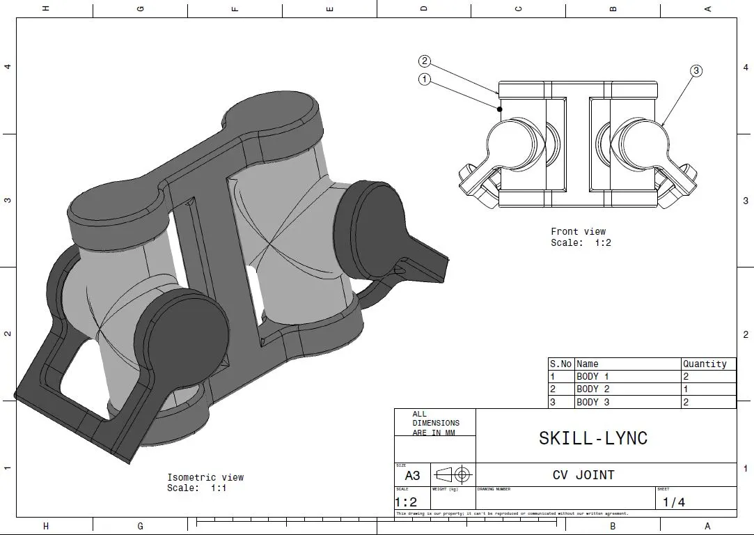
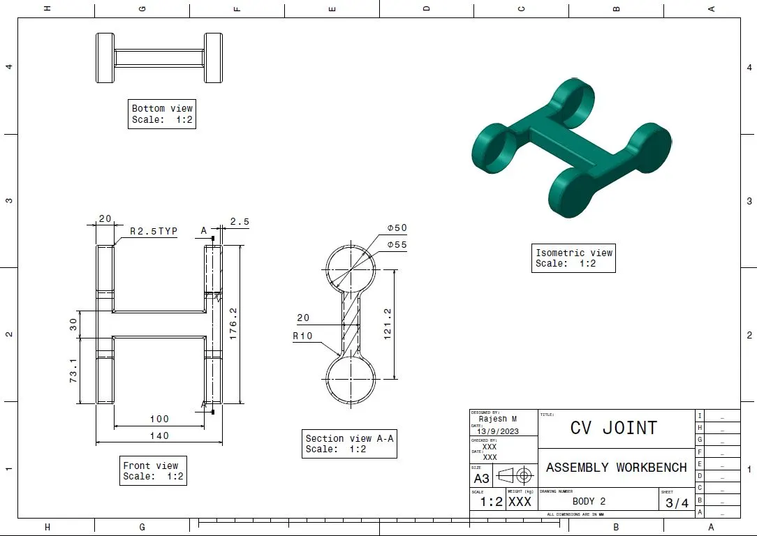
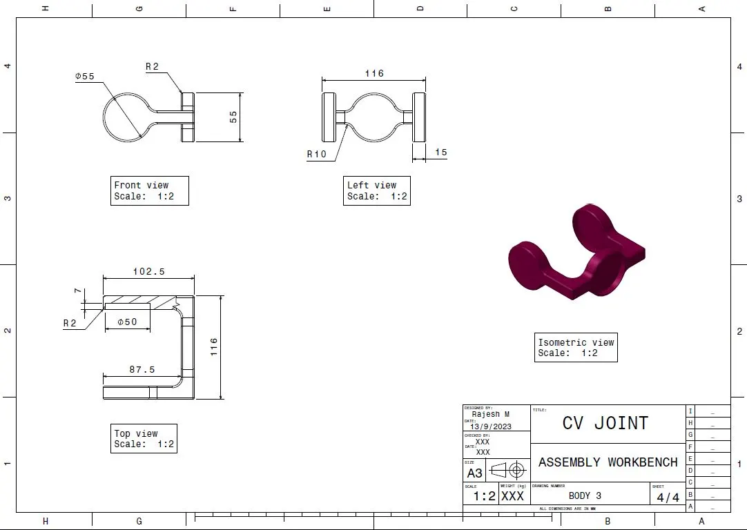
Given drawing: CV Joint
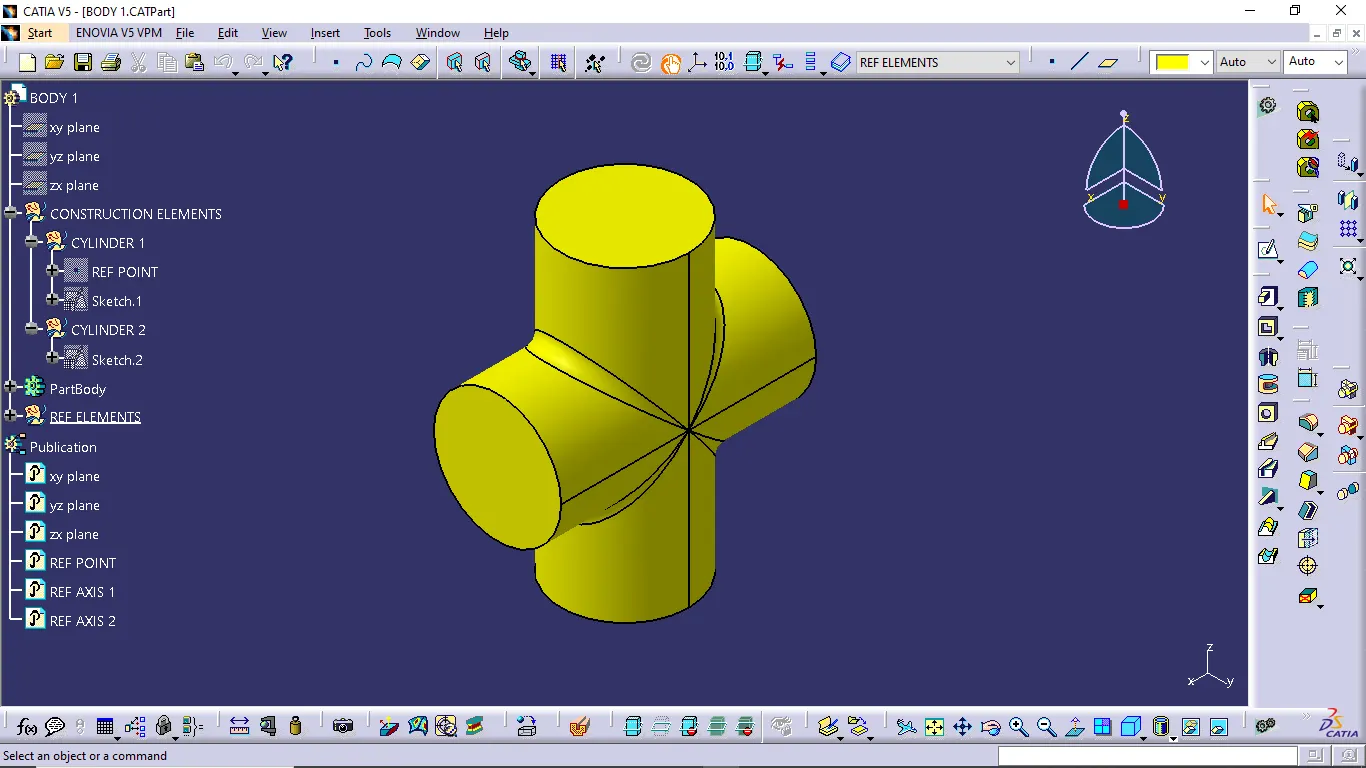
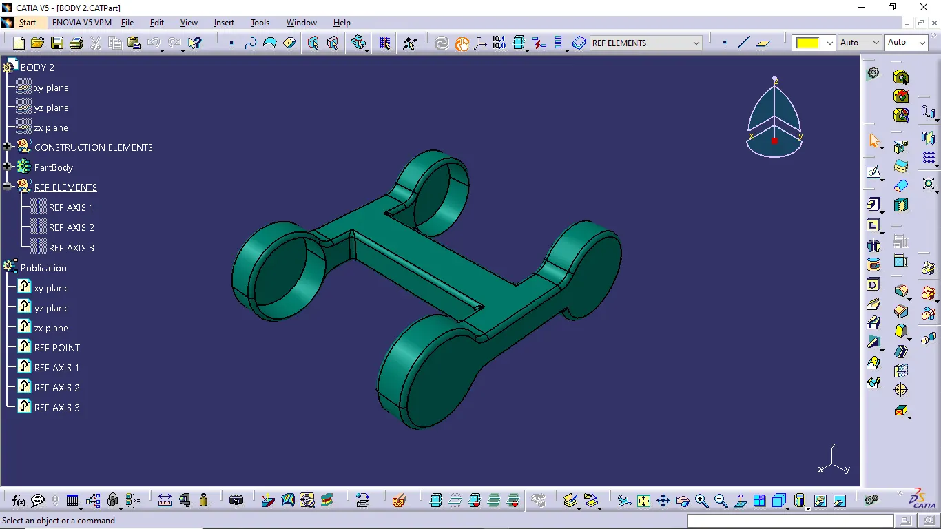
Creating Part files:
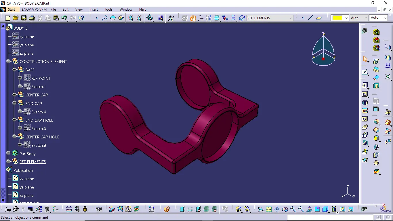
Assembly Workbench:
Drafting:
Conclusion:
Thus, the given 2D drawing created an individual part file and assembled together. Also, drafted into 2D drawing.