Week 7 Challenge - Assembly Workbench
AIM-:
- CREATE THE PART FILE FOR ALL 2D DRAWING.
- ASSEMBLY WITH GIVEN PROPER CONSTRAINT.
- DRAFTING FOR PART DESIGN AS WELL AS ASSEMBLY DESIGN AS GIVEN IN CHALLENGE.
A) PROCEDURE FOR MODEL 1 AND MODEL 2 PART DESIGN-:
1. Apply the position sketch for all part drawing.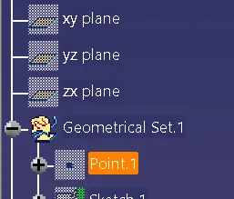
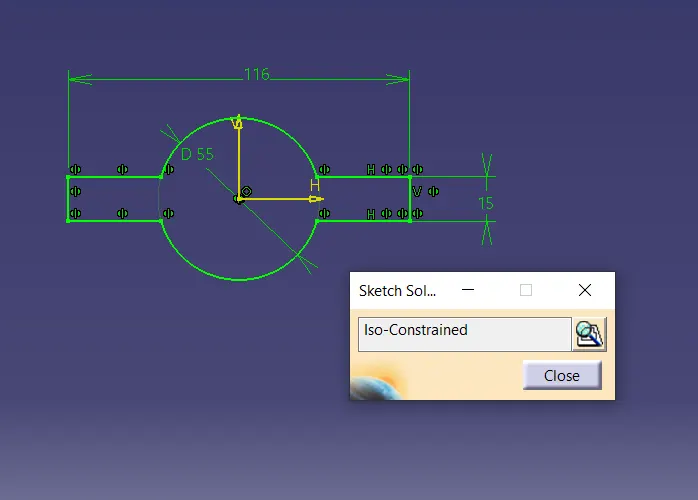
2. sketch the ISO CONSTRAINT 2d drawing with given dimension as given in challenge master section for all part design file.
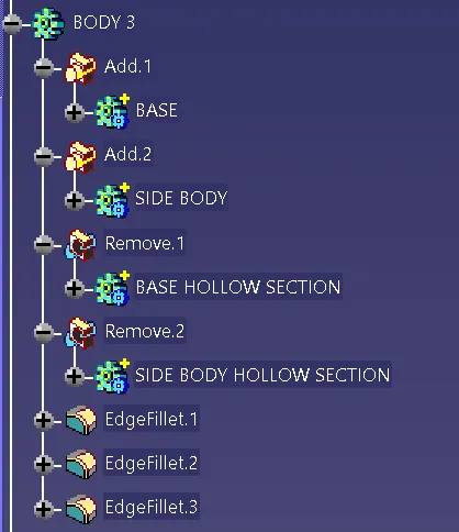
3. Use the boolean operation to create 3d drawing with proper dimension.
4. After create 3d, apply chamfer and edge fillet as per given master section in challenge.
B) PROCEDURE FOR MODEL 1 AND MODEL 2 ASSEMBLY DESIGN-:
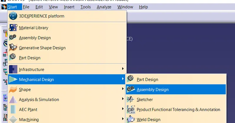
1. Open th assembly work bench (start, mechanical design, assembly design)
2. Copy the part file and paste it in the product workbench.
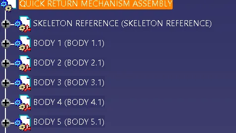
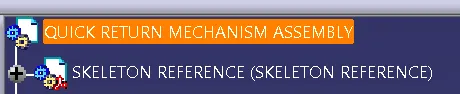
3. Change the name of product as per assembly name given in master section.
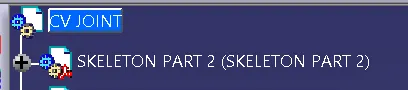
4. Insert geometrical set for reference element for each part body.
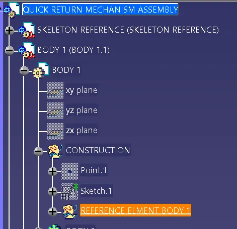
5. Create the axis reference on reference elemnet wherever it is required for each part body.
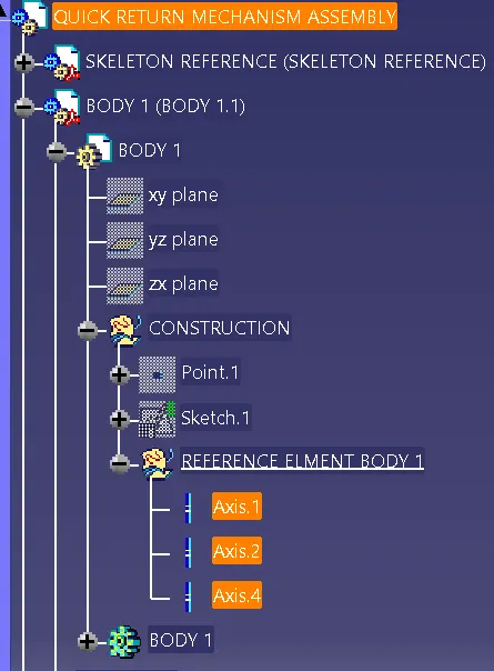
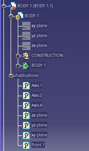
6. Publish all the part body xy plane, yz plane, zx plane, point (position sketch) and axis separately in part body.
- Select xy plane, yz plane, zx plane, point (position sketch) and axis
- Then go to the Tools,publication,yes and ok.
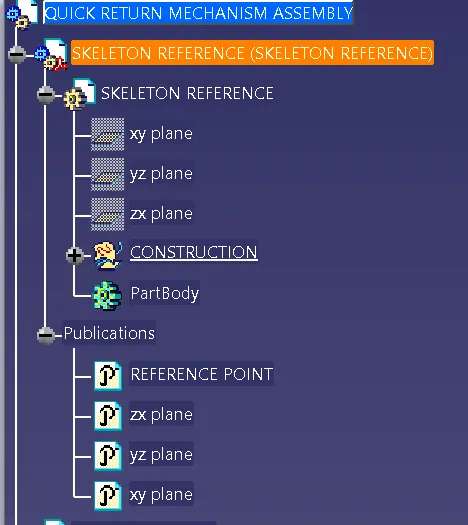
7. Insert one part name given as skeleton reference, create point then publish xy plane, yz plane, zx plane and point in this file also.
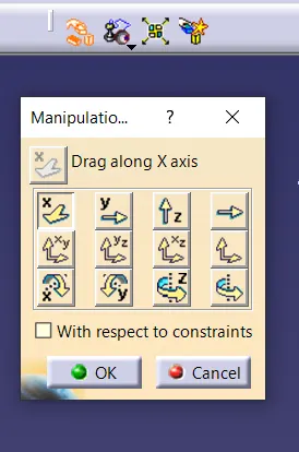
8. Apply manipulation command to move all the body in x,y or z plane.
9. Fix the skeleton point reference first by giving fix component constraint.
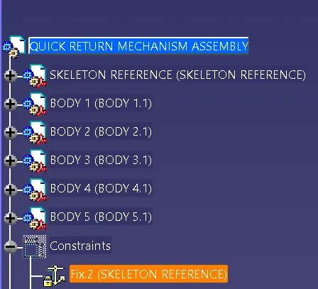
10. Give coincidence constraint from fix point to first body (whichever is placed there).
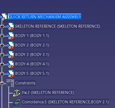
11. Apply coincidence constraint, contact constraint, offset constraint etc wherever it is required and assembled all the part body.
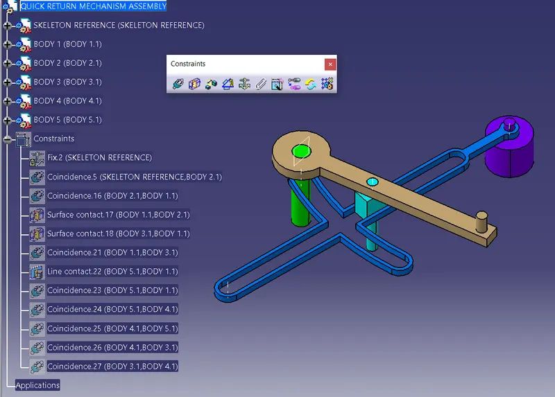
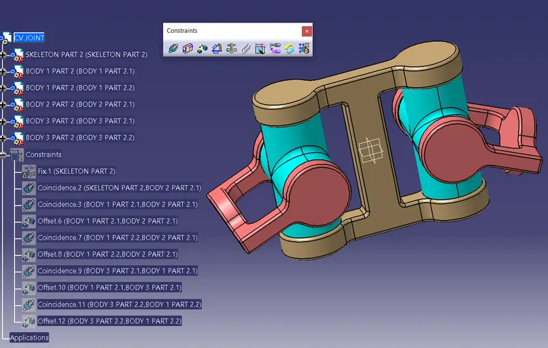
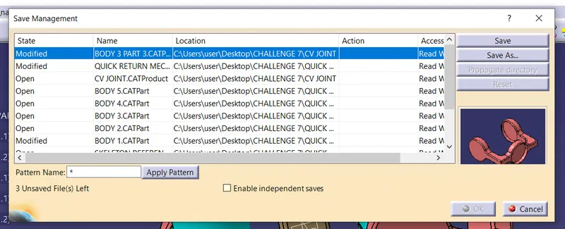
12. After assembly, save the main assembly file by going FILE, Save Management, Save as, choose location, then Propagate directory to save all the file in one folder or in one place then ok.
C) PROCEDURE FOR MODEL 1 AND MODEL 2 PART BODY DRAFTING-:
1. Open the drafting page by (File, new, drawing,ok, ISO, Sheet Style, landscape and ok.)
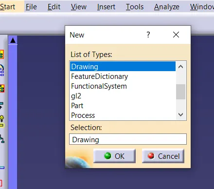
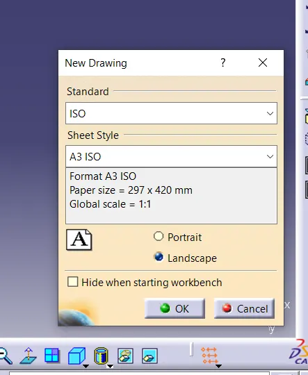
2. For Frame and Tiltle Block, go to the the Edit, Sheet Background.
3. Then Insert, Drawing, Frame and Title Block, Style of Title Block (Choose any of them), Create ok.
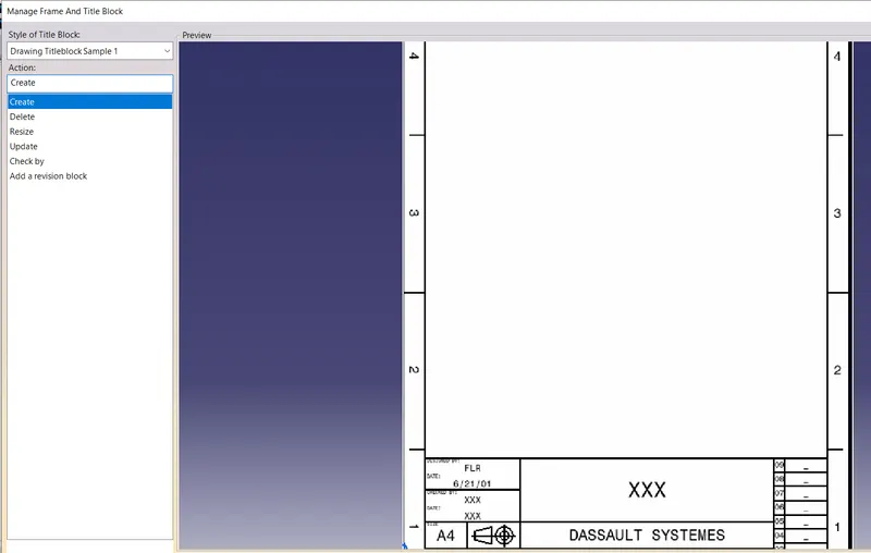
4. For edit on Title Block, Double click on the text.
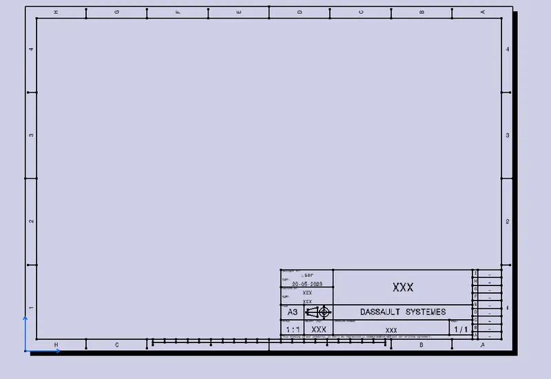
5. Then go the Edit, Working view.
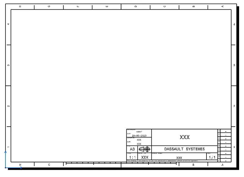
6. For front view, go to the Front View, Window, choose ( .Cat file or .Cat product file), select the face of body, rotate model if required, click on display. Front view is projected.
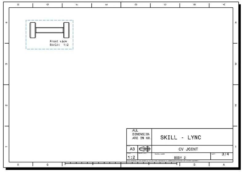
7. For Side or Top view, first double click on front view frame, projection view, drag from front view, click where it is placed.
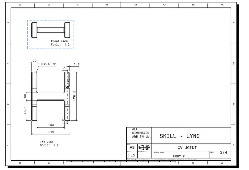
8. For Isometric view, go to the Isometric View, Window, choose ( .Cat file ), select the face of body, rotate model if required, click on display. Isometric view is projected.
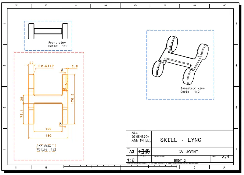
9. For Section View, first double click on view frame, go to the Offset Section View, create line, double click on display, drag the isometric view, then left click on display. Section view is projected.
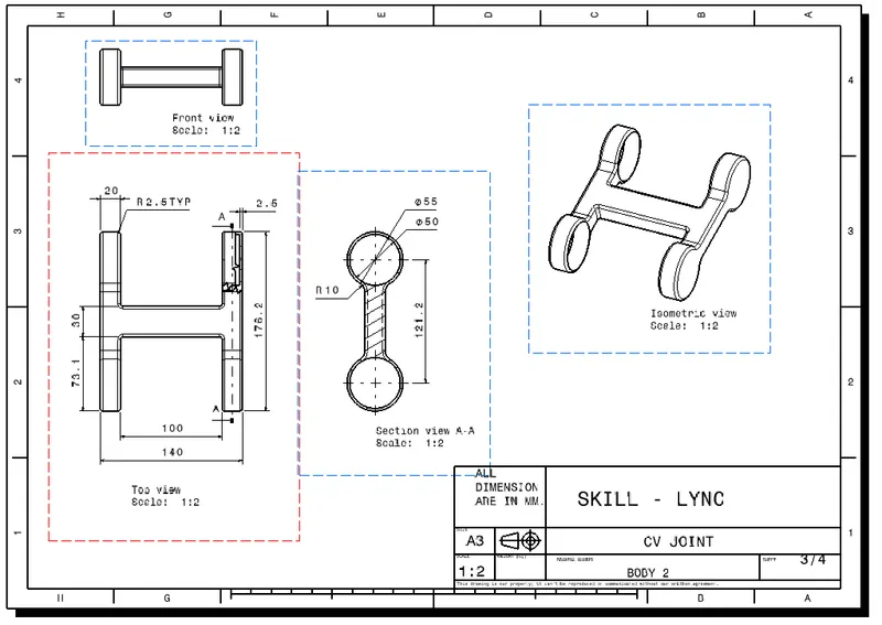
10. For section in middle portion, first double click on view frame, go to the Breakout View, create close shape (where it required), ok.
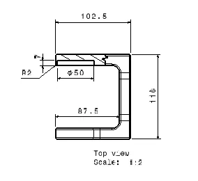
11. For edit (Like scale,hidden line, display view frame etc), right click on view, properties, choose, ok.
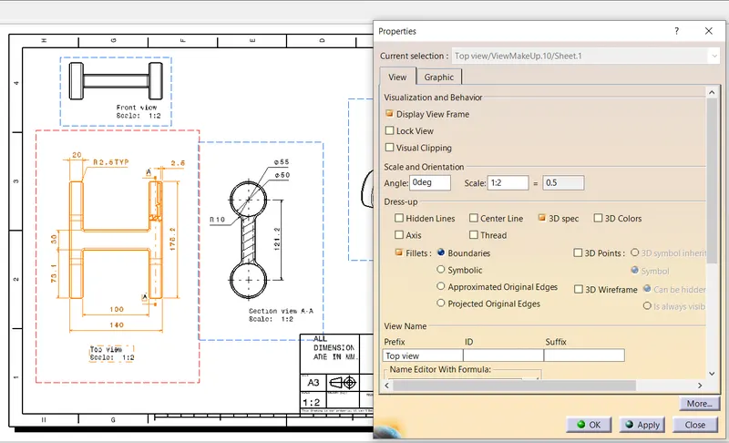
12. Dimension all the view as per master section given in challenge.
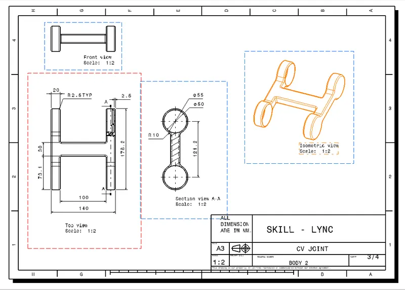
13. For save the file, go to the File, save management, save as, choose place, ok.
C) PROCEDURE FOR MODEL 1 AND MODEL 2 ASSEMBLY DRAFTING-:
1. Open the drafting page by (File, new, drawing,ok, ISO, Sheet Style, landscape and ok.)
2. For Frame and Tiltle Block, go to the the Edit, Sheet Background.
3. Then Insert, Drawing, Frame and Title Block, Style of Title Block (Choose any of them), Create ok.
4. For edit on Title Block, Double click on the text.
5. Then go the Edit, Working view.
6. For front view, go to the Front View, Window, choose ( .Cat product file), select the face of body, rotate model if required, click on display. Front view is projected.
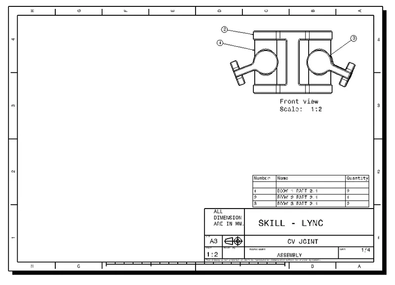
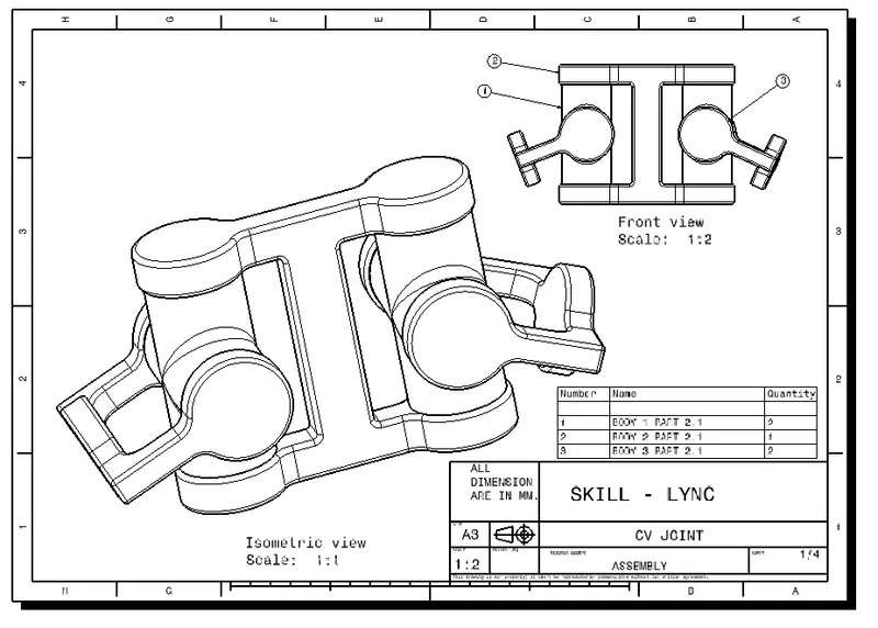
7. For Ispmetric view, go to the Isometric View, Window, choose ( .Cat product file), select the face of body, rotate model if required, click on display. Isometric view is projected.
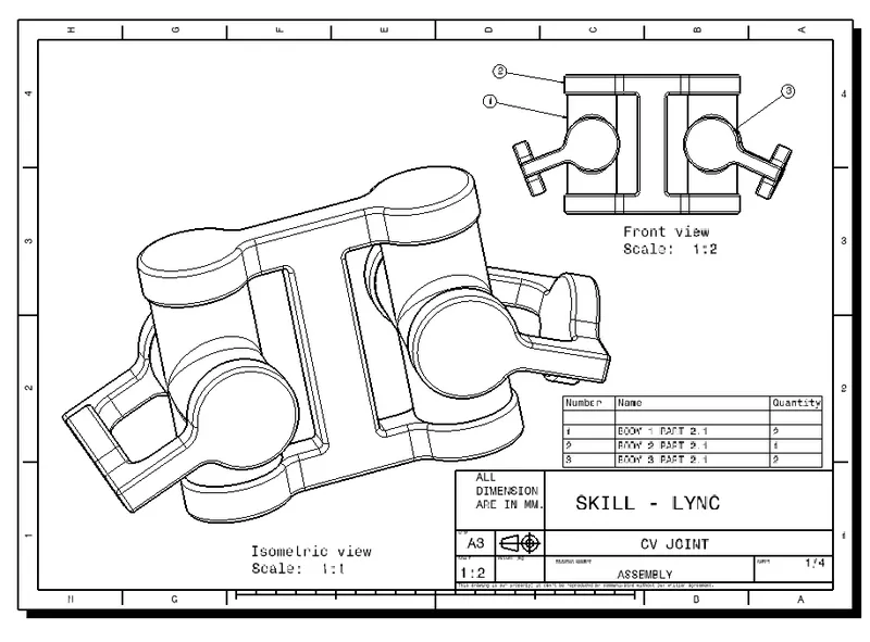
8. For Bill of Material, Go to the assembly file, Generating Number, select product name,Mode,ok.
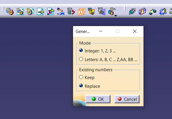
9. For Bill of Material, go to the Analyze, Bill of Material,Define Formats, choose display properties, ok.
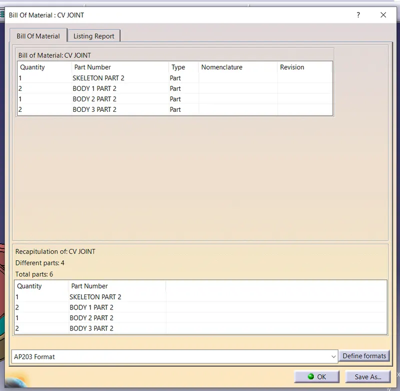
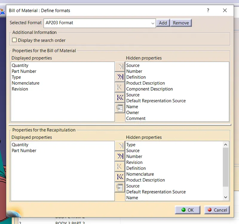
10. For Balloon Generation, Go to the drafting working page, Insert, Generation, Balloon Generation.
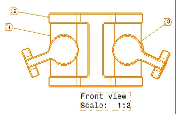
11. For Bill of Material, Go to the drafting working page, Insert, Generation, Bill of material, bill of material. For edit on bill of material, double click on table and edit it.
12. For save the file, go to the File, save management, save as, choose place, ok.
Conclusion
All the dimension should be follow as per given master section in challenge. Also give the proper constraint for assembled the part body. Publication is required for proper assembly.