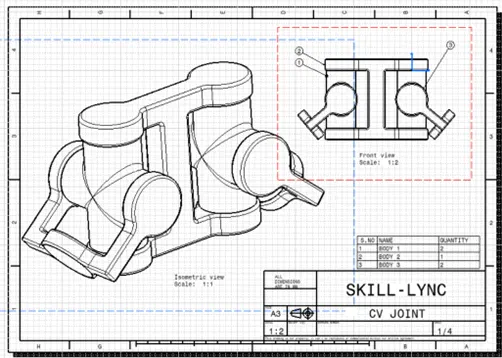
Week 7 Challenge - Assembly Workbench
Assembly Design:
For an assembly, a dedicated assembly workbench is present in the CATIA software. To access it got to start > mechanical design > assembly design.
First, with help of given 2D sketches of the parts that are to be assembled are created using part workbench. Following are the parts needed for Assembly 1-
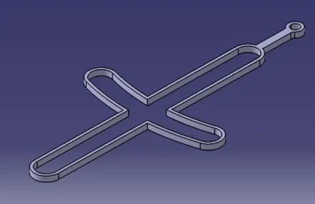
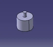
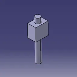
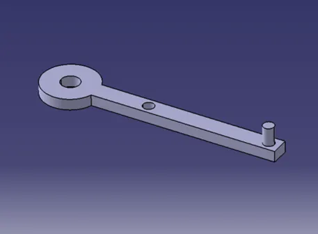
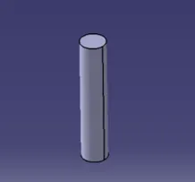
(Part 1) (Part 2) (Part 3) (Part 4) (Part 5)
Once all parts are created, we need to open the assembly workbench. Now, to insert all those parts we need to copy each part and paste it in the product file in assembly workbench.
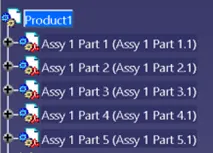
(Parts in product file)
Now, all the parts may be overlapping each other hence, a tool named as Manipulation is used to move the parts to the point that all parts are individually visible in the workspace. Now, we need to constrain the degrees of freedom of all the parts and assemble them to the parent part. We can choose any part as a parent. Here, I have chosen Part 1 as my parent part. Parent part is important as all the other parts will be assembled respective to its position. Therefore, the parent part should be restricted first and fixed to constrain its movement.
For this, a tool Fix Component is used. It is a type of constraint which fixes a part at its given position.
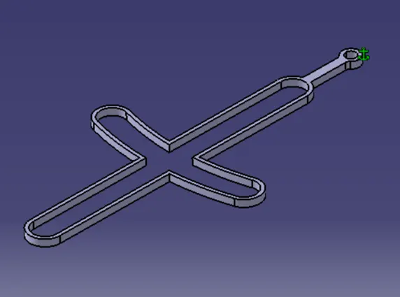
(Fixing Constraint on Part 1)
Further, to assemble the parts at their respective position we need to bring them together at their positions. For this Coincident Constraint is used. This constraint will coincide any two parts coaxially or by two points. The axes and points coincide to restrict the translation and rotational motions of the part. Hence, all parts are given points and axes to the faces which will meet together in assembly. Now, with the help of coincidence constraint one by one axis to axis and point to point of the parts are constrained. At the last, click on the update button to see if the given constraints bring the part together at ther given positions according to assembly drawing.
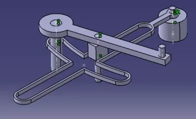
(Final Assembly)
Drawing For Assembly 1:
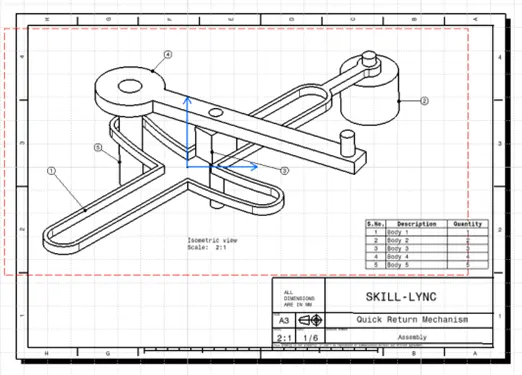
Assembly 2:
Similar steps are followed for Assembly 2.
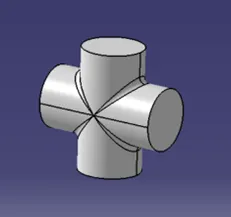
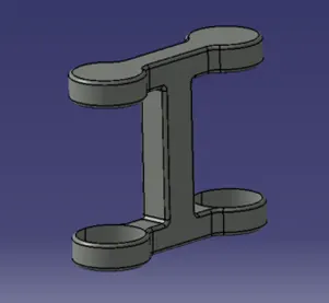
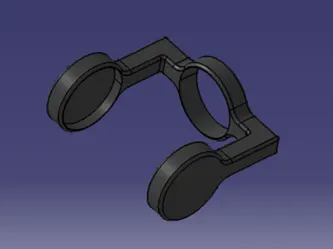
(Part 1) (Part 2) (Part 3)
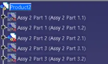
(Parts in product file)
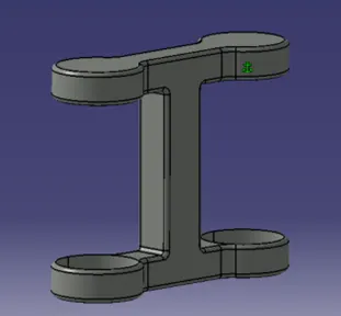
(Fixing Constraint on Part 2)
For Part 2 and Part 3 I have used Offset constraint to orient their faces according to the given assembly as it they were not orienting properly with using only coincident constraint.

(Final Assembly)
Drawing For Assembly 2: