Week 8 - Challenge 2 - Switch Bezel Design
Tooling axis:
A tooling axis/ tooling direction is the direction in which core side and the cavity side of the mould are pulled apart from each other. Generally, tooling direction is decided by the geometry of the component design. Deciding the tooling axis to create maximum portion of the part is essential for the manufacturer of the mould as it will affect the cost of the manufacturing process and the product directly. In the given class-A surface there is a pocket like structure having fillets hence, the tooling axis should be perpendicular to it.
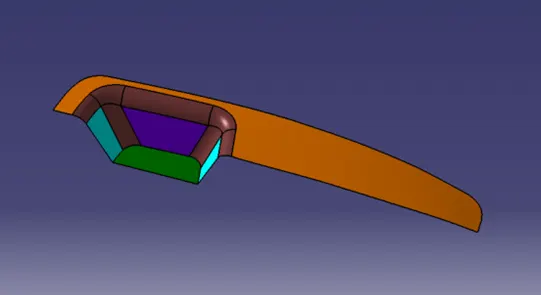
(Class-A Surface)
Creation of tooling axis using Bisecting line method-
Now, as the direction is confirmed an accurate tooling axis needs to be created. To do so, a method in which a bisecting line is created between the faces which are parallel to the tooling direction is used. This method ensures the exact angle at which a tooling axis should pass through and proper draft angle is maintained. In the above image, the faces in cyan and violet colours are the parallel faces to the tooling direction. Since there are parallel faces on different planes different dummy tooling axes are created as the base for main tooling axis.
By projecting the intersection of the part through yz plane, first dummy tooling axis is created. This axis is formed through bisecting the two lines passing through the intersection of cyan coloured faces. Similarly, second tooling axis is created on zx plane. Since there is no intersection on the other side for bi-section a line passing through the main horizontal axis at an angle from the projected intersection is created. This angle is taken as 3 degrees for minimum drafting.
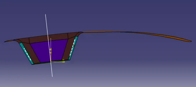
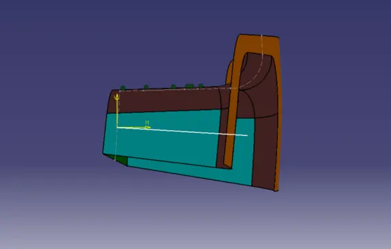
(Dummy Tooling Axis 1) (Dummy Tooling Axis 2)
With the help of both dummy axes a new axis is created using the bisecting command in the line tool. This is the main tooling axis required.
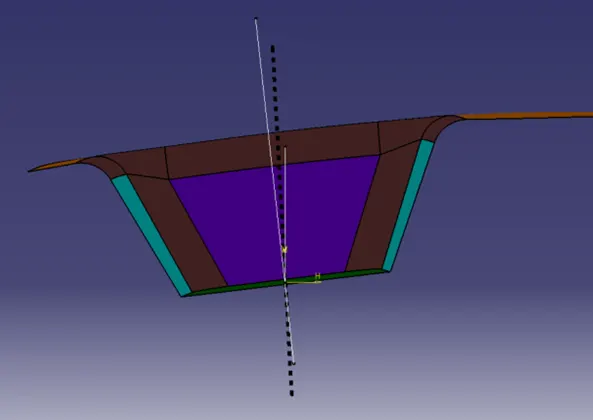
(Tooling Axis)
Draft analysis:
Draft analysis is a method checking the draft angles of the part in order to decide whether the CAD part is manufacturable or not. In a mould, the material inserted tends to stick to its surface after cooling and makes it difficult for ejection of the created part. If the mould has straight 90 degrees angle from the base, then it will be almost impossible to eject the part from the mould which in turn could damage the mould as well. To ease this process the part will have small draft angles at every area. For sheet metal components the minimum draft angle is 7 degrees and for plastic components it is minimum 3 degrees.
This draft analysis is done using the draft analysis tool present in the part design as well as generative shape design work bench. It can also be accessed through Insert tab > Analysis > Draft Analysis.
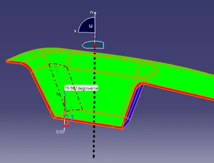
Following is the draft analysis performed on the Class-A surface.
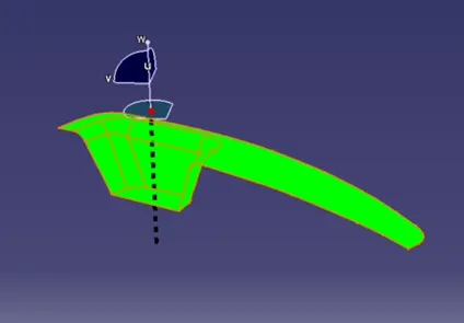
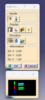
(Class-A Surface Draft Analysis) (Colour Scale)
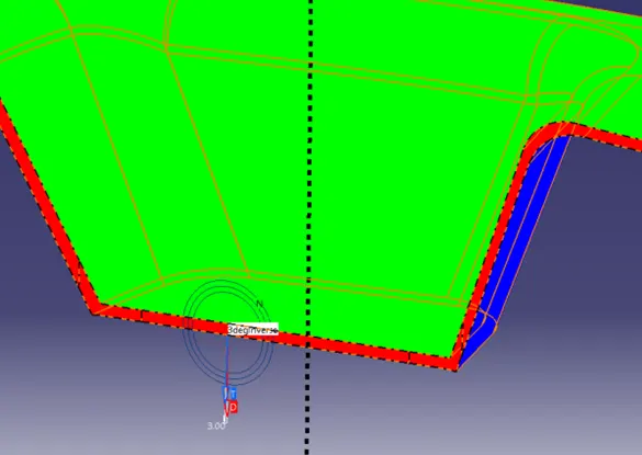
In the above image, the color scale shows that the green color indicates the surfaces having more than 3 degrees of draft angle, red color indicates the surfaces having draft angle between 0 to 3 degrees and blue color indicates less than 0 degrees of draft angle. The compass is placed on the tooling axis to determine the draft direction.
Following is the draft analysis performed on the final part model.
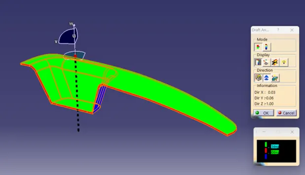
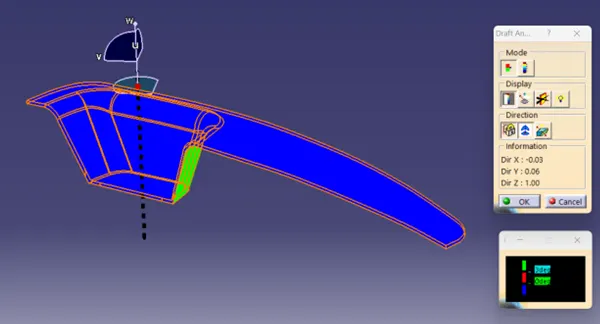
The same procedure is followed as for the class-A surface. With the help of inverse direction command in the direction option of the draft analysis dialogue box, we can change the draft direction to check the opposite side of the part for draft angles.
Draft analysis from different 3D views-
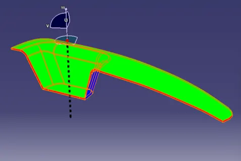
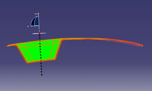
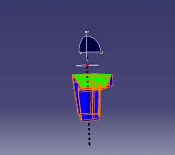
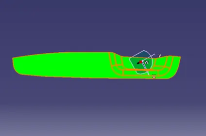
(Isometric View) (Front View) (Side View) (Top View)
To check the draft at each point, select the option analysis under running point in the display option of the draft analysis dialogue box.