Week 7 Challenge - Assembly Workbench
In this week’s assignment, you will have to create 2 assemblies according to the content covered in the course videos. You will be provided with 2D diagrams of the components and you will have to first create the individual part files and then create a complete assembly of those part files in the assembly workbench. After creating the assembly make use of the drafting tools to create a 2D drawing similar to the one given in the assignment folder.
The diagrams for the assignment are provided in the link mentioned below. Assume all the unmarked dimensions as you see fit.
PROCEDURES:
- initially we creating a solid models by using given inputs( part dimensions).
- Once we get it, and we go to assembly design workbench.
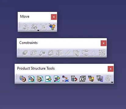
- Assembly design tool commands
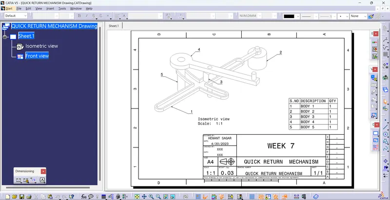
MODEL-1 QUICK CRANK MECHANISM :
In this quick return mechanisms we required 5 parts. First we create a required 5 parts.
Then open the assembly workbench, insert the required part files.
Then manupulate the all parts, then fix the any one part use fix tool.
Then assemble the all parts respect to fixed parts.
Use constrain tool, fist constrain required part and fixed part ,then update.use offset tool then fixed properly, now assemble the first part. Do the same procedure for a rest parts.
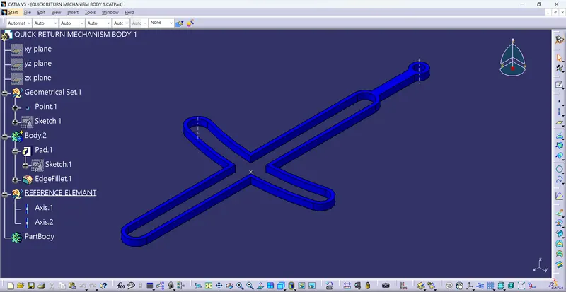
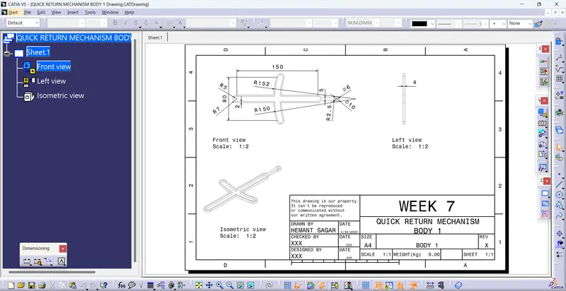
BODY 1
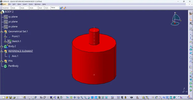
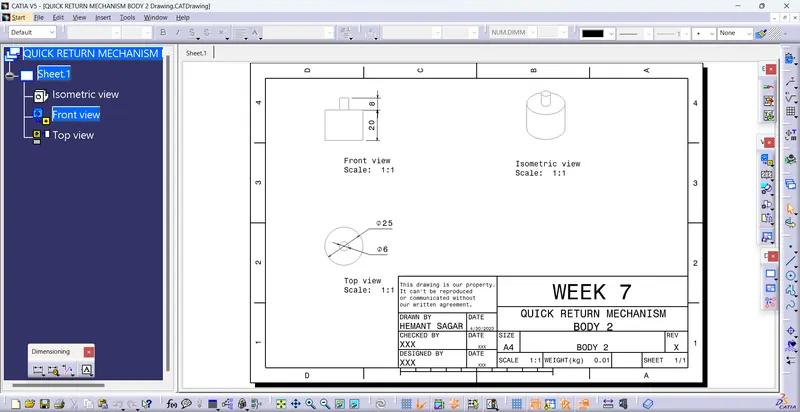
BODY 2
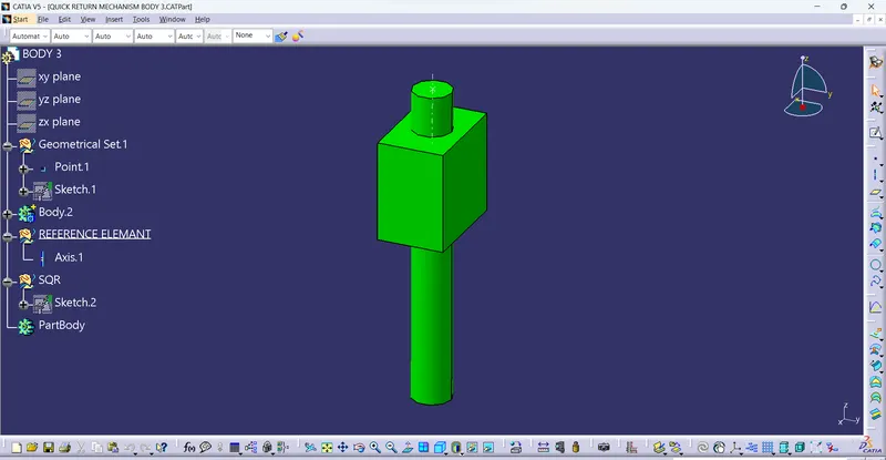
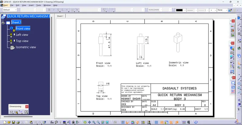
BODY 3
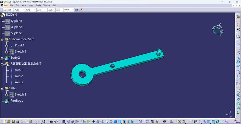
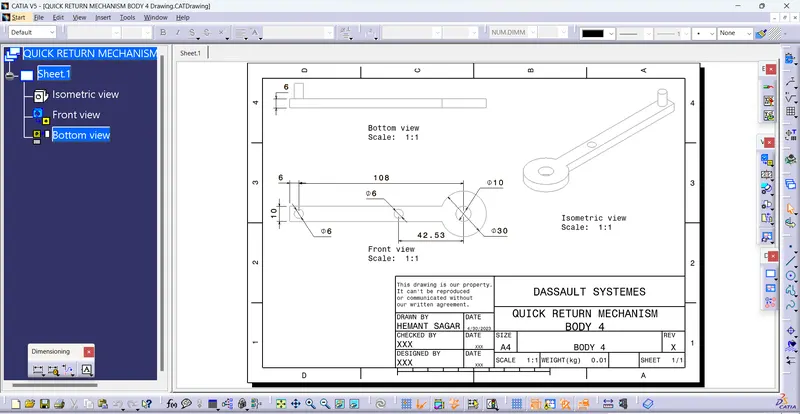
BODY 4
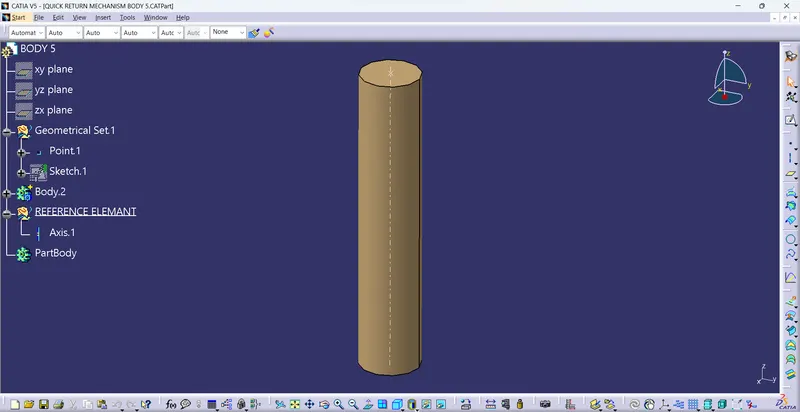
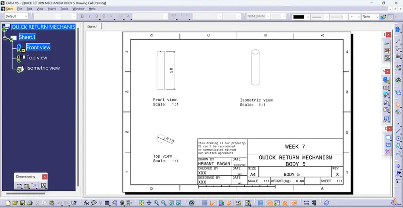
BODY 5
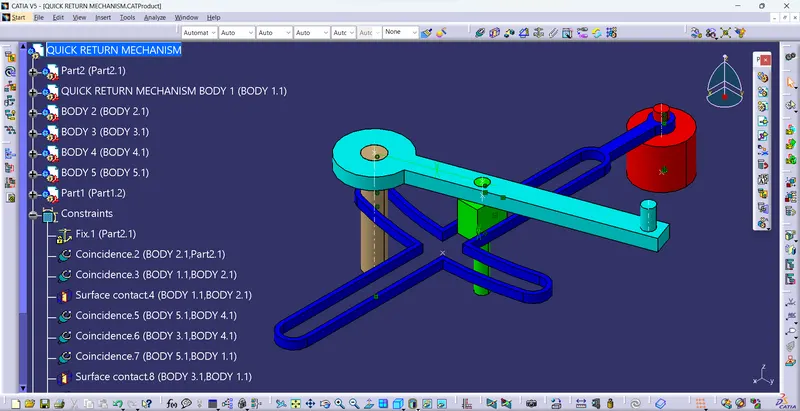
ASSEMBLY BODY OF THE QUICK RETURN MECHANISM :
I had selected a new product file and copied the all part files of the assembly bodies and paste in the product file.
After i took a part file for skeleton reference and i had fix the skeleton part file and and given the coincidence constraint for the bodies to form a ASSEMBLY BODY.
MODEL-2 CONSTANT VELOCITY JOINT :
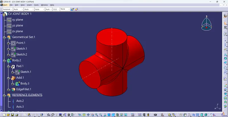
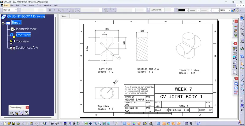
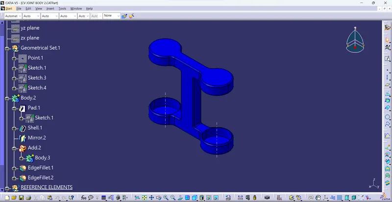
In this constant velocity joint we required 3 parts. First we create a required 3 parts.
Then open the assembly workbench, insert the required part files.
Then manupulate the all parts, then fix the any one part use fix tool.
Then assemble the all parts respect to fixed parts.
Use constrain tool, fist constrain required part and fixed part ,then update.use offset tool then fixed properly, now assemble the first part. Do the same procedure for a rest parts.
BODY 1
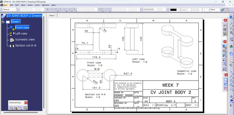
BODY 2
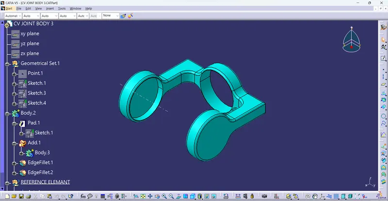
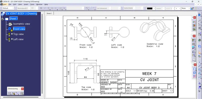
BODY 3
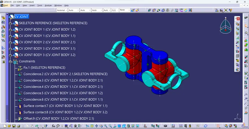
ASSEMBLY BODY OF THE CONSTANT VELOCITY JOINT :
I had selected a new product file and copied the all part files of the assembly bodies and paste in the product file.
After i took a part file for skeleton reference and i had fix the skeleton part file and and given the coincidence constraint for the bodies to form a ASSEMBLY BODY.
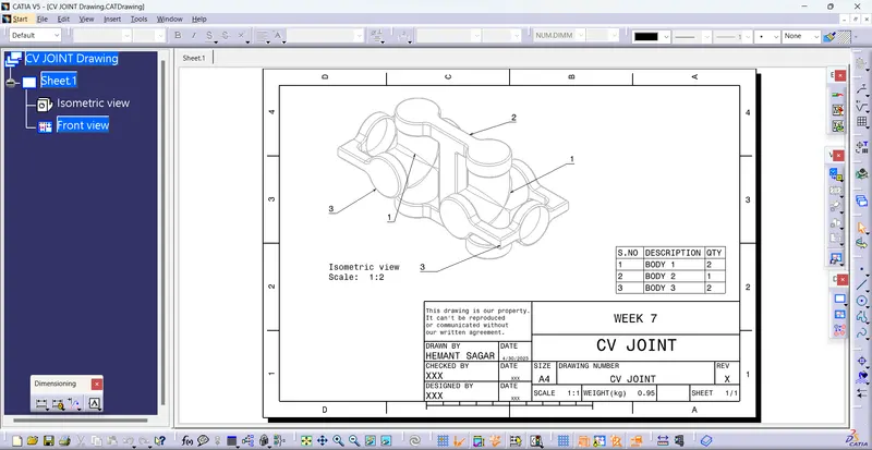
RESULTS:
created 2 assemblies according to the content covered in the course videos. You will be provided with 2D diagrams of the components and you will have to first create the individual part files and then create a complete assembly of those part files in the assembly workbench. After creating the assembly make use of the drafting tools to create a 2D drawing similar to the one given in the assignment folder.
hence it is proved...