Project 1
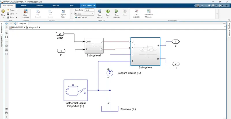
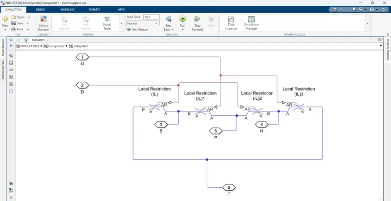
Develop a double-acting actuator model using Simscape Multibody and Simscape components. The mechanical system of the cylinder needs to be built using Simscape Multibody library components / blocks, and the hydraulic system needs to be modelled using Simscape library physical components.
CYLINDER MODEL
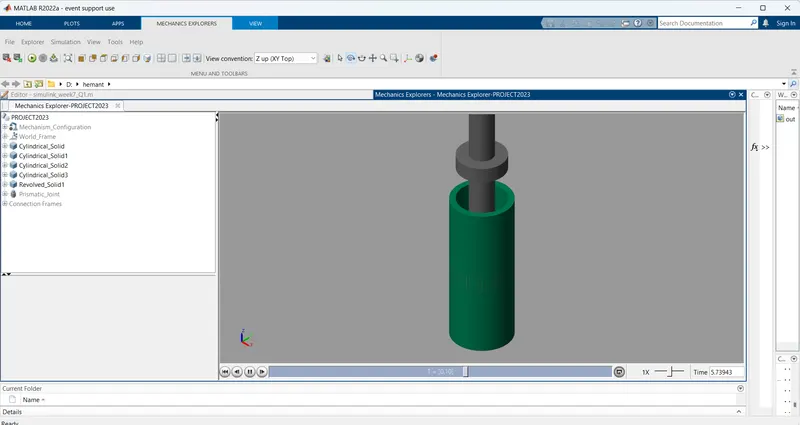
The cylinder is shown on the schematics in three different positions partially retracted, fully retracted, and fully extended.
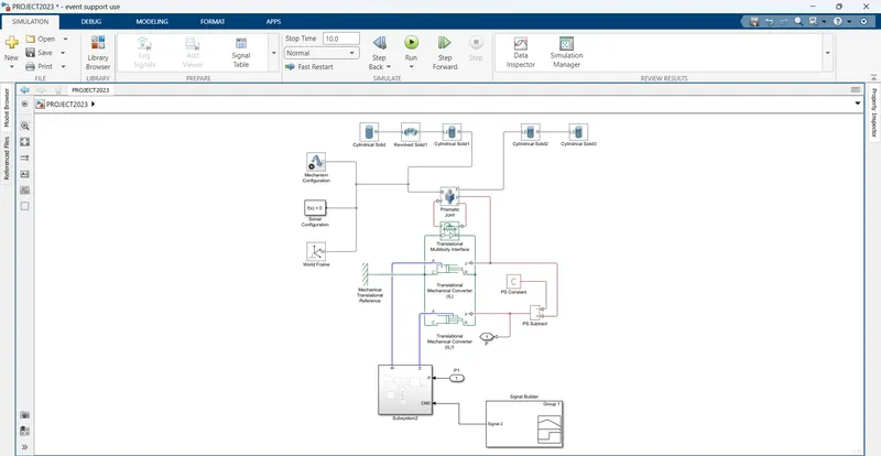
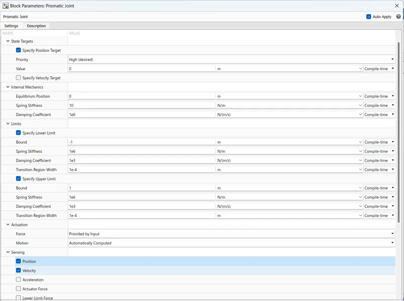
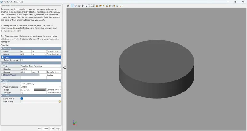
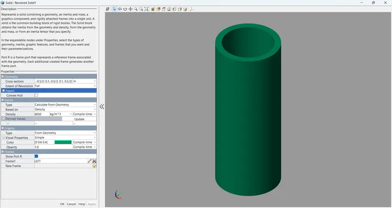
Simscape Multibody allows you to simulate the system's mechanical component. The Revolved Solid (Simscape Multibody) and Cylindrical Solid (Simscape Multibody) blocks, for instance, can be used to depict the cylinder and piston. Use a Prismatic Joint (Simscape Multibody) block to provide the piston the translational degree of freedom. The base frame (B) and follower frame (F) of the joint can be attached to the centres of the left inner surface of chamber A and the left surface of the piston, respectively, to make it simple to compute the lengths of chambers A and B. Make sure that chamber B is in the centre of both the B and F frames' Z-axes.
Using this convention, the length of the chamber A, d A, equals the joint block's output position, and the length of the chamber B, d B, is equal to the difference between d A and the stroke length. You may set the top and lower position limitations of the Prismatic Joint block to make sure the piston doesn't go past the cylinder's ends.
DOUBLE ACTING CYCLINDER
Double-acting actuators employ air pressure to open and close the valve, in contrast to single-acting actuators. The most common type of pneumatic valve actuator is this one. Due to the lack of mechanical springs in the majority of models, double-acting actuators are used since they are more affordable and have a longer lifespan. High-quality double-acting actuators frequently cycle through millions of times before failing.
1.Piston Assembly:
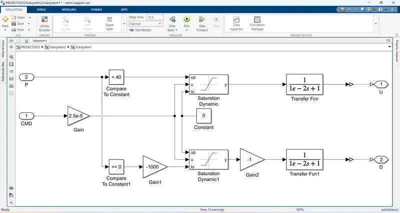
The inlet or outlet flow inside the barrel pushes the Piston or Plunger of hydraulic cylinders. When the Piston moves to either side of the cylinder, the Rod contracts or expands.
These are the parts of the basic hydraulic cylinders. More types of cylinders are more complex in their construction. However, these components are essential to almost all hydraulic cylinders, and it is good to know what they are and how they work.
2.Prismatic Joint:
A prismatic joint is often called a slider — for example, a “crank-slider linkage.” This is a type of kinematic pair and an idealized way to describe how motions are constrained within machines.
There are several physical embodiments of a prismatic joint, such as slideways. Rectangular cross-sections may be used in combination with plain or rolling bearings to enable linear motion while preventing rotation about the axis of movement.
Hydraulic and pneumatic cylinders are typically modeled as prismatic joints although they may also permit rotation about their axis. Kinematic pairs are classified as higher pairs and lower pairs. Higher pairs involve point or line contact, such as a ball or roller that’s rolling over a surface. Lower pairs can be visualized as surface contact.
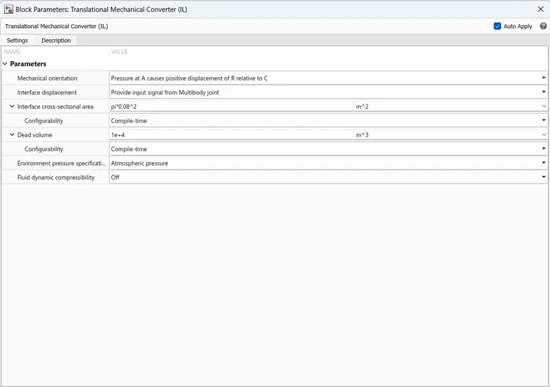
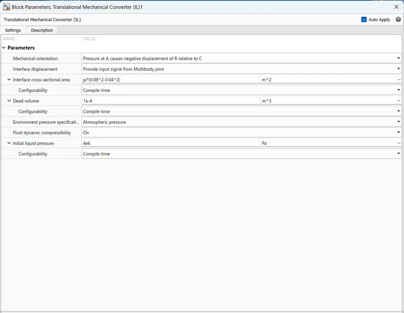
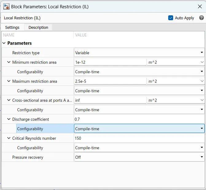
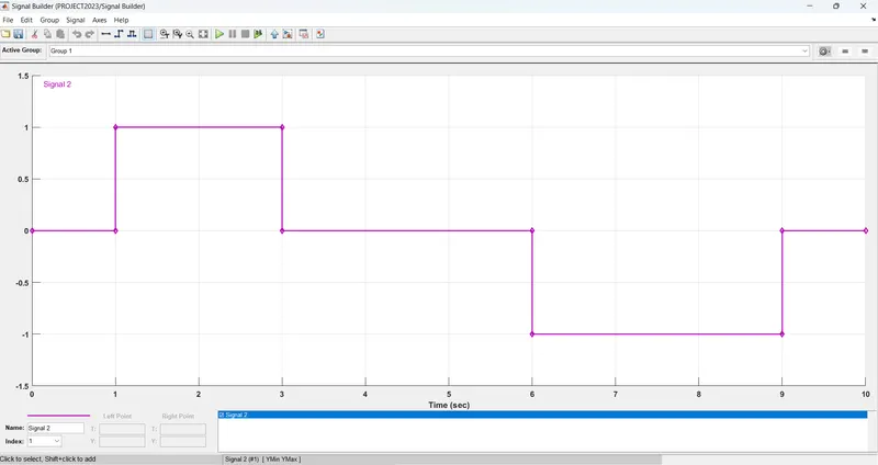
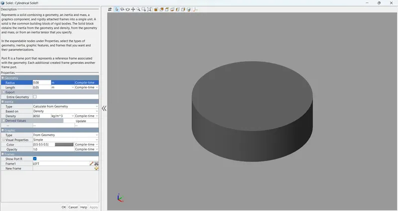
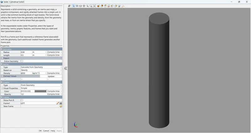
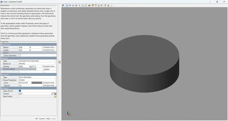
Result: The animation of the acutuator can be observed while running the Simulink file attached below.