Week 7 Challenge
Introduction
The first step in vehicle performance modelling is to produce an equation for the tractive effort. This is the force propelling the vehicle forward, transmitted to the ground through the drive wheels.
Consider a vehicle of mass m, proceeding at a velocity v, up a slope of angle ψ, as in below figure.
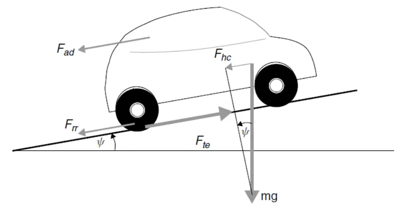
The force propelling the vehicle forward, the tractive effort, has to accomplish the following:
- overcome the rolling resistance;
- overcome the aerodynamic drag;
- provide the force needed to overcome the component of the vehicle’s weight acting down the slope;
- accelerate the vehicle, if the velocity is not constant.
Rolling resistance force
The rolling resistance is primarily due to the friction of the vehicle tyre on the road.
Friction in bearings and the gearing system also play their part. The rolling resistance is
approximately constant, and hardly depends on vehicle speed. It is proportional to vehicle weight. The equation is:
Frr = µrr m g
Where µrr is the coefficient of rolling resistance.
The main factors controlling µrr are the type of tyre and the tyre pressure. Any cyclist will know this very well; the free-wheeling performance of a bicycle becomes much better if the tyres are pumped up to a high pressure, though the ride may be less comfortable.
The value of μrr can reasonably readily be found by pulling a vehicle at a steady very low speed, and measuring the force required.
Typical values of μrr are 0.015 for a radial ply tyre, down to about 0.005 for tyres developed especially for electric vehicles.
Aerodynamic drag
This part of the force is due to the friction of the vehicle body moving through the air. It is a function of the frontal area, shape, protrusions such as side mirrors, ducts and air passages, spoilers, and many other factors.
The formula for this component is:
Fad = ½ ρACdv2
where ρ is the density of the air, A is the frontal area, and v is the velocity. Cd is a constant called the drag coefficient.
The drag coefficient Cd can be reduced by good vehicle design. A typical value for a saloon car is 0.3, but some electric vehicle designs have achieved values as low as 0.19.
There is greater opportunity for reducing Cd in electric vehicle design because there is more flexibility in the location of the major components, and there is less need for cooling air ducting and under-vehicle pipework. However, some vehicles, such as motorcycles and buses will inevitably have much larger values, and Cd figures of around 0.7 are more typical in such cases.
The density of air does of course vary with temperature, altitude and humidity. However a value of 1.25 kg.m−3 is a reasonable value to use in most cases. Provided that SI units are used (m2 for A, m.s−1 for v) then the value of Fad will be given in Newtons.
Hill climbing force
The force needed to drive the vehicle up a slope is the most straightforward to find. It is simply the component of the vehicle weight that acts along the slope. By simple resolution of forces we see that:
Fhc = m g sin(Ψ)
Total tractive effort
The total tractive effort is the sum of all these forces:
Fte = Frr + Fad + Fhc
where:
- Frr is the rolling resistance force, given by equation
- Fad is the aerodynamic drag, given by equation
- Fhc is the hill climbing force, given by equation

We will discuss the subsystem Vehicle_model in detail here
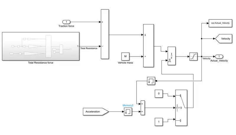
Our aim is to calculate the velocity for a given traction force. The basic equation here is
Force = mass * acceleration
acceleration = Force / mass
then by integrating the accelearion we can get velocity.
The above logic is created in the simulink model attached above.
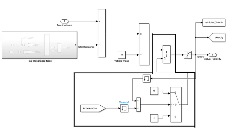
The logic inside the marked black line is created to avoid the intergral wind up. Let us see what is integral wind up briefly,
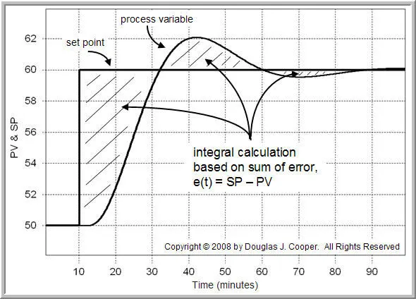
Integrator windup is a problem that results in overshoot that would not occur if the system were being controlled only in its linear range.
The linear range of a control system can be limited by saturation of the feedback controller output. The rise time of a system step response when the controller must initially be saturated is longer than that of the step response in the linear region. Because of this, the integrator will accumulate a larger output during the rise, causing overshoot.
Integrator anti-windup can be used to avoid this overshoot.
The tractive force should be subtracted from the total resistance of a moving vehicle so that we can get a actual force that is availabe for moving the vehicle forward.
The logic for calculating the resistance in given inside the subsystem Total_Resistance
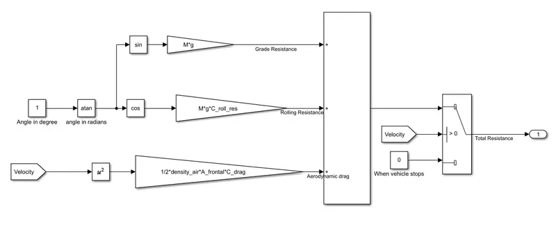
The actual velocity calculated against the given tractive force is attached here
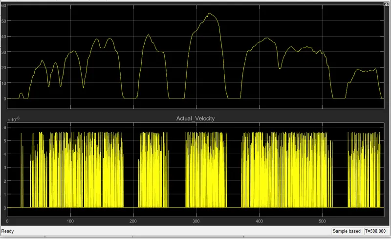
The input signal is fed by using signal bulider block(a drive cycle is created as signal in this block), and the simulation time is set to 598s.
The velocity required to move the vehicle forward is calculated as shown in the above scope results.