Week 7 Challenge
1)
ANS:-
AIM:- To set up model for RC Building design base on the parameters for cover.
PROCEDURE:-
- Firstly we have to open new file in TEKLA software using new icon present in file tab.
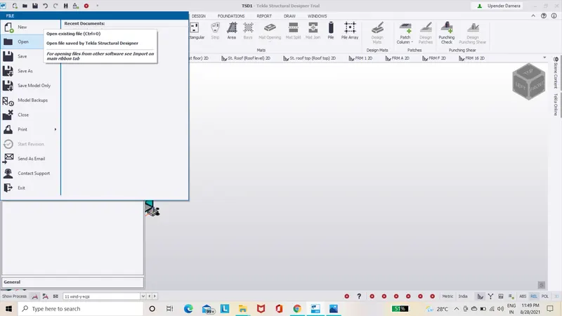
- Now let us select the settings icon from the home tab.
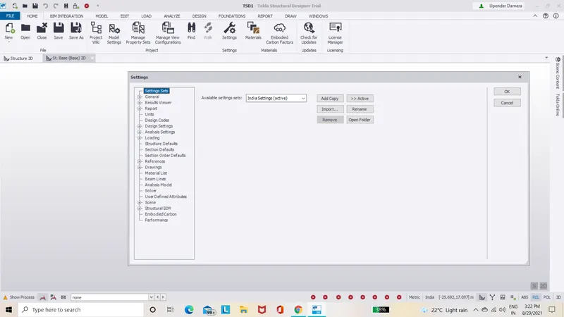
- After selecting the settings icon a dialog box appears then let us modify settings according to our model that includes design codes,units as shown below.
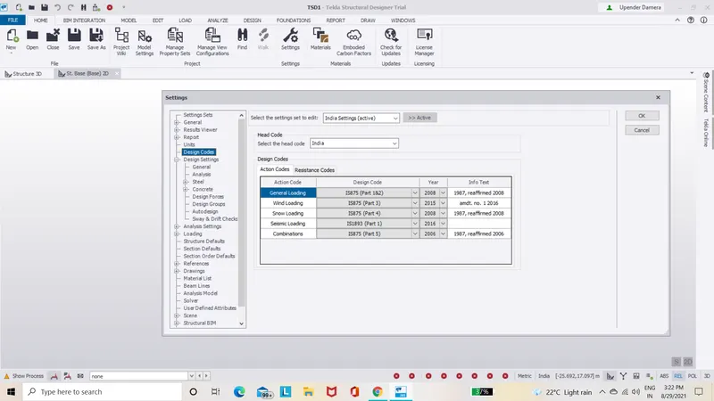
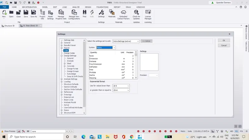
- Now we will set up the model for the given parameters by using structure defaulits.
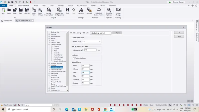
- We can also change the cover after modeling the element in property window.
- Similarly we can change design settings of beams,columns,foundation,slabs and walls.
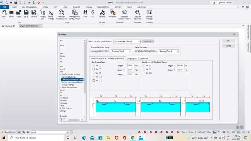
- Save the file by using save as icon.
RESULT:-
We have successfully created a new file in TEKLA and set up model for RC building Design based on the given parameters.
2)
ANS:-
AIM:- To model grids as per the attachment 2,2.1,2.2.
PROCEDURE:-
- First select consrtuction levels from model menu.
- Construction level dialog box appears on the screen.
- Enter the levels with appropriate name and height.
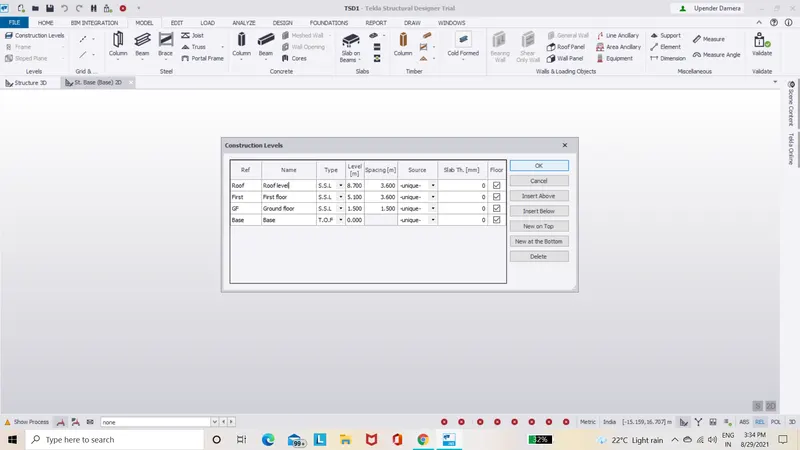
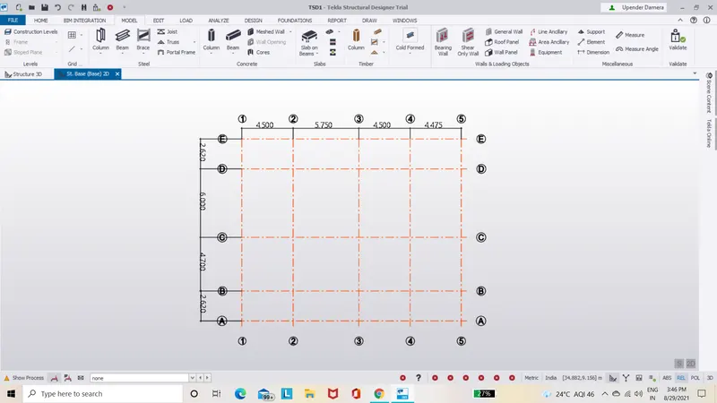
- Next select grids option and draw a horizontal grid line.
- Next using parallel quick option draw the remaining grid lines.
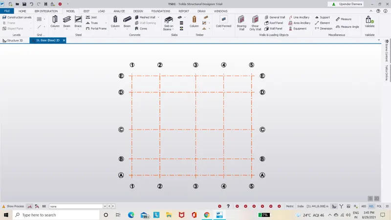
- Repeat the same procedure for vertical grid lines.
RESULT:-
With tha above steps we can create construction levels and draw grid lines for the structure.
3)
ANS:-
AIM:- To study the layout and write a summery for general arrangement of the structure.
PROCEDURE:-
- First we have to open the attatchments provided. Next we have to analyze and check where to place the columns.
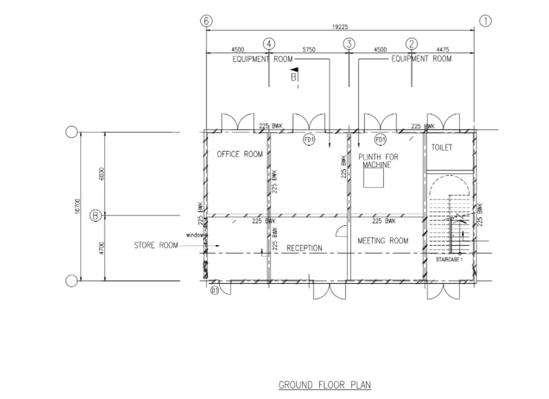
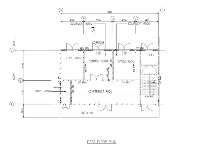
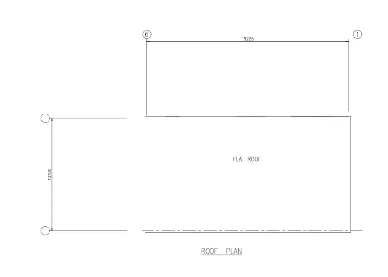
- Now open attatchment 2 ground floor and paste the image into paint to draw the columns and beams position.
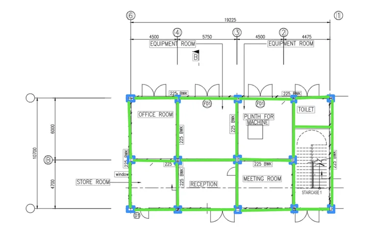
- Repeat the same for attachment 2.2 First floor.
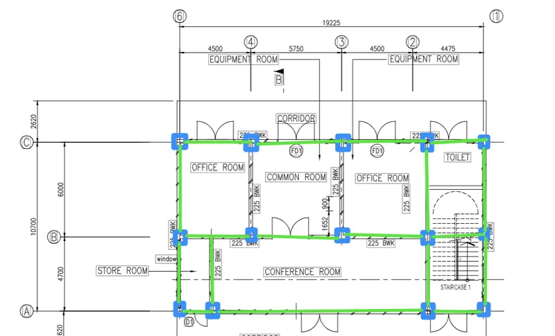
It is neccessary to check and identify all the components in the plan .All the plans designed cannot be implemented perfectly. We may face certain issuses and problems at the site or workplace,So it is necessary to study the plan cmpletely . Some issues can only be found once we start the work at site ,and that is when the major role of a civil engineer plays. The plan should be observed keenly and the structure should be imagined.With this software we can analyze the structure before construction, So thats where the important of the software fails.
RESULT:-
With the above steps we can draw the major requirements in paint,which will be helpful further designing of the building.
4)
ANS:-
AIM:-
PROCEDURE:-
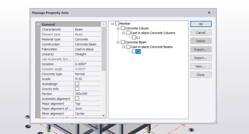
- First we have to go to the manage properties and definen member properties which are concret column as M30 & size 400x400 and beam as M30& size 230x500.
- And also define slab property as 200 overall depth and concrete type as M30 as shown below.
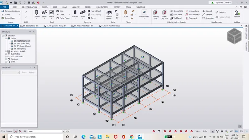
- Then open the base plan and select column tool and place concrete colummn where ever required.
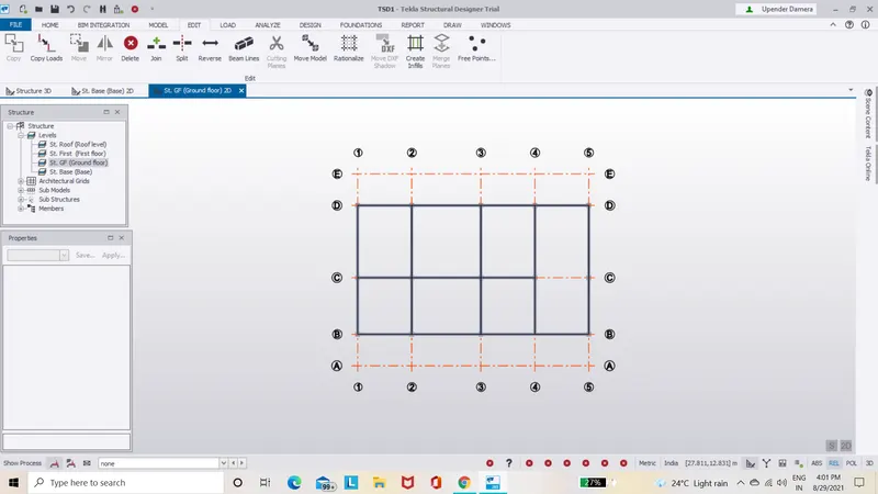
- Next construct concrete beams joining the columns as shown below.
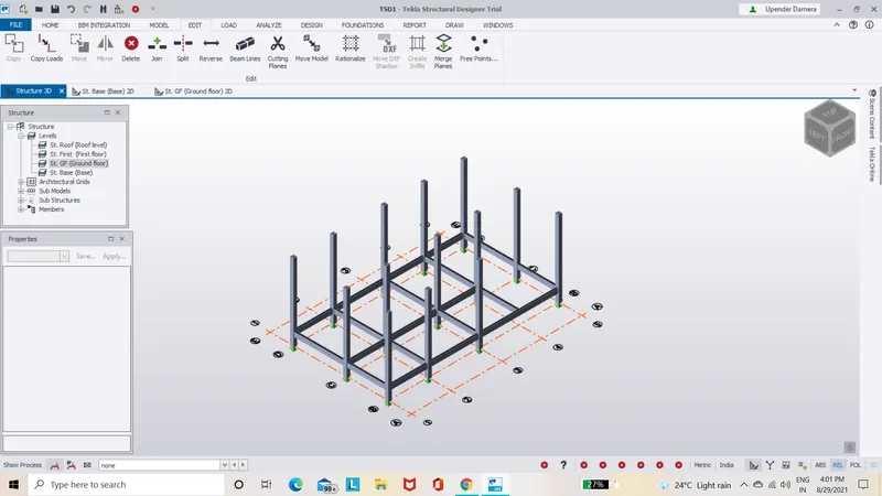
- Next we have to repeat the same procedure for the first floor and roof level.
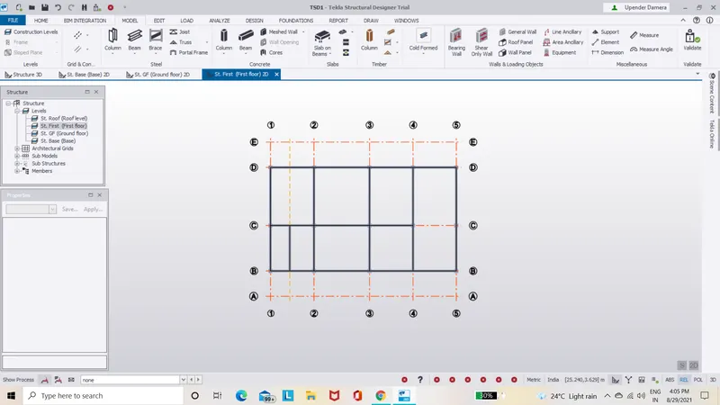
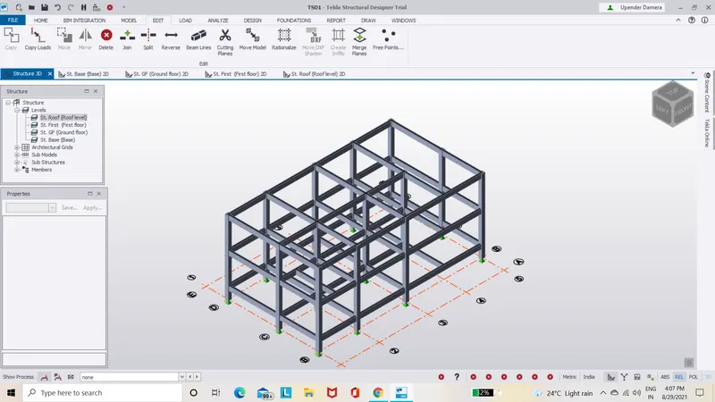
- Next go to model tab select the slab on beams option.
- Next go to manage proprty set and define the slab propty and click the cursor where ever we want the slabs.
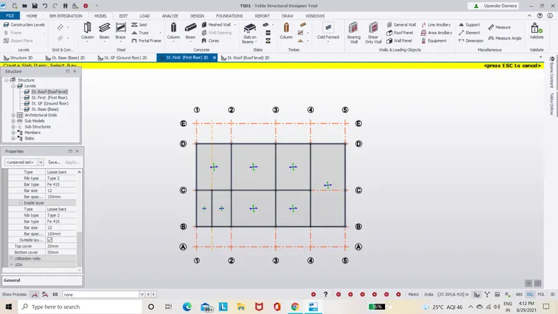
- Repeat the same process for first floor and roof level as shown below.
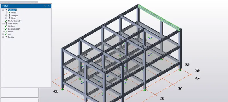
- At last click on validate option to verify weather the structure is free from errors as shown below.
RESULT:-
With the above steps we can construct concrete columns,concrete beams and slab for the structure.