Creating a Floor plan, Footing detail and Isometric view using AutoCad
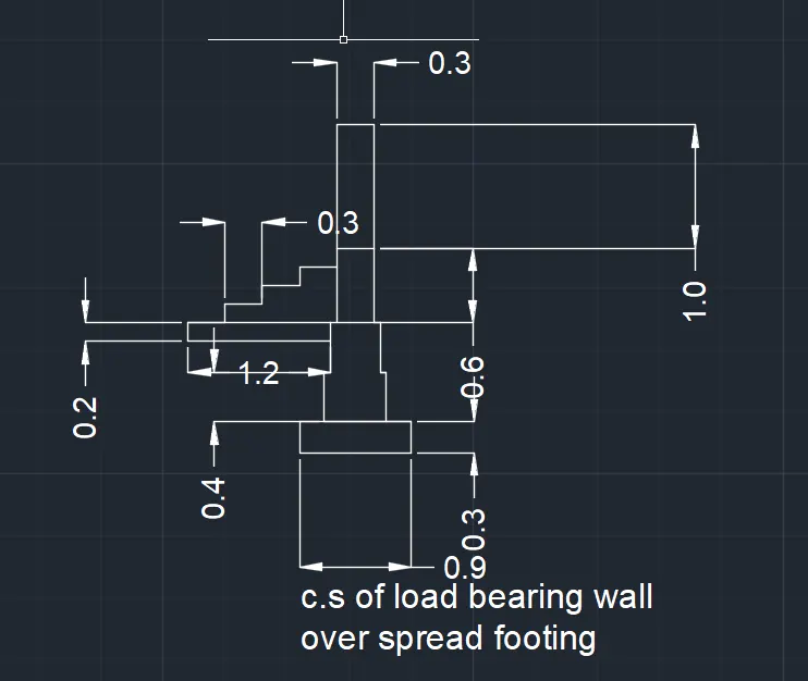
AIM:Draw the the c.s of load bearing wall over the spread footing.
procedure:
- open the autocad and set the units and limits as per the drawing requirements.
- next start the drawing by using various commands like line,circle,rce,etc.
- in the above drawing all the lines are drawn by using line command in command box .
- The dimesions are given by using the command dime.
- The footings and columns are drawn by using line command .
- below text is wrote by using text command in above ribbon section.
- And also use offset command for the object which has same length.
commands used in the above drawing are
- line command
- text command
- dimension command
- offset command
- trim command
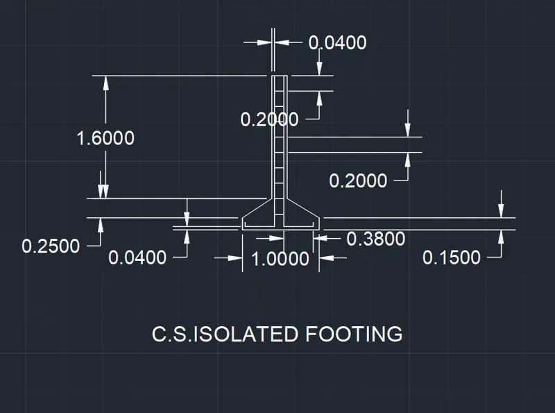
AIM:To Draw the the c.s .isolated footing by autocad .
procedure:
- first open the autocad and set the units and limits as per the drawing requirements.
- next start the drawing by using various commands like line,circle,rce,etc.
- in the above drawing all the lines are drawn by using line command in command box .
- The dimesions are given by using the command dime.
- The footings and columns are drawn by using line command .
- below text is wrote by using text command in above ribbon section.
- And also use offset command for the object which has same length.
commands used in the above drawing are
- line command
- text command
- dimension command
- offset command
- trim command for remove unwanted objects.
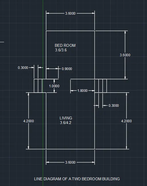
AIM:To draw the line diagram of a two bedroom building by using autocad.
procedure:
- first open the autocad and set the units and limits as per the drawing requirements.
- next start the drawing by using various commands like line,circle,rce,etc.
- in the above drawing all the lines are drawn by using line command in command box .
- The dimesions are given by using the command dimension.
- below text is wrote by using text command in above ribbon section.
- And also use offset command for the object which has same length.
commands used in the above drawing are
- line command
- text command
- dimension command
- offset command
- trim command for remove unwanted objects.
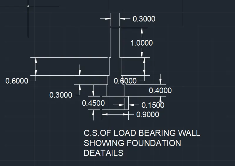
AIM:To draw the c.s.of load bearing wall showing foundation details by using autocad.
procedure:
- first open the autocad and set the units and limits as per the drawing requirements.
- next start the drawing by using various commands like line,circle,rce,etc.
- in the above drawing all the lines are drawn by using line command in command box .
- The dimesions are given by using the command dimension.
- below text is wrote by using text command in above ribbon section.
- And also use offset command for the object which has same length.
commands used in the above drawing are
- line command
- text command
- dimension command
- offset command
- trim command for remove unwanted objects.
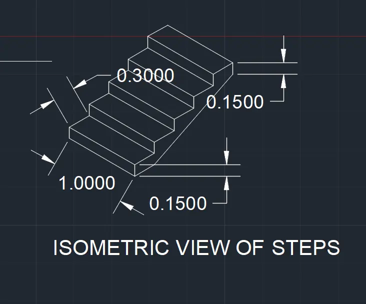
AIM:To draw the isometric view of steps by using autocad.
procedure:
- first open the autocad and set the units and limits as per the drawing requirements.
- to draw the above drawing go to drafting settings in that click on snap and grip and select isometrc view.
- And also use the f5 key to change the angles.
- next start the drawing by using various commands like line,circle,rce,etc.
- in the above drawing all the lines are drawn by using line command in command box .
- The dimesions are given by using the command dimension.
- below text is wrote by using text command in above ribbon section.
- And also use offset command for the object which has same length.
commands used in the above drawing are
- line command
- text command
- dimension command
- offset command
- trim command for remove unwanted objects.
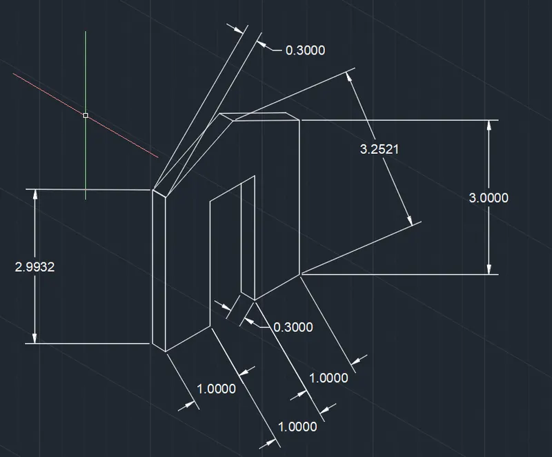
AIM:To draw the isometric view of gable wall by using autocad.
procedure:
- first open the autocad and set the units and limits as per the drawing requirements.
- to draw the above drawing go to drafting settings in that click on snap and grip and select isometrc view.
- And also use the f5 key to change the angles.
- next start the drawing by using various commands like line,circle,rce,etc.
- in the above drawing all the lines are drawn by using line command in command box .
- The dimesions are given by using the command dimension.
- below text is wrote by using text command in above ribbon section.
- And also use offset command for the object which has same length.
commands used in the above drawing are
- line command
- text command
- dimension command
- offset command
- trim command for remove unwanted objects.