Week 7 Challenge
- Introduction: When constructing a bridge across a river, a portion of the foundation will be submerged in water. Horizontal forces are induced by the water movement on the submerged section. Water current forces are greatest at the top of the water level and zero at the bottom of the water level, or at the bed level.
Many cross-sea bridges have been constructed or in construction in the Chinese coastal areas, such as Hangzhou Bay Bridge, East China Sea Bridge and Hong Kong-Zhuhai-Macau Bridge, etc. Usually the foundations of cross-sea bridges will bear the load of wave and current simultaneously, the extreme value of which is an important factor for bridge design. It is quite difficult to estimate the extreme wave-current forces on bridge foundations due to their complex form, for example a polygonal platform pier shape on piles.
AIM: Calculate the Current Force on the given Bridge and apply in the Staad Model for Analysis of the bridge.
Force on submerged bridges
Fd=1/2XΡxCdxVxVxA
FL=1/2xPxCLxVxVxA
Mg=1/2xPxCmxVxAxLref
Although current bridge is not a submergible
PROCEDURE:-
As per given data
The high flood level (HFL) is 2 m above the foundation level.
Mean Velocity (v) = 3m/sec
Water Current Forces as per IRC
P=52xKxV 2
Where P= Intensity of pressure due to water current in KN/m 2
V= Maximum velocity of the current at the point where the pressure intensity
B2eing calculated in m/sec.
K= Shape factor=0.66 for circular pier.
V=Maximum Velocity
= SQRT (2) x Mean velocity
= SQRT (2) x 3=4.24 m/sec
P= 52x0.66x4.24x4.24=616.99 KN /m2
Load on the circular pier (pier diameter =2m)
Circumference of ½ circle=22/7X2/2=3.14 m
Uniformly Varied Load on the pier =616.99X3.14=1937KN/m
Load on the Abutment (diameter=1.065) as per given data
Circumference of ½ circle=22/7X1.065/2=1.672 m
Uniformly Varied Load on the pier =616.99X1.672=1031.6 KN/m
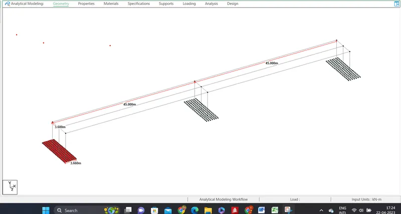
Fig-1
-
From Above Fig-1
- Create a single Node with coordinates (0.000, 0.000, 0.000)
- And create another node at the distance of 7.6 m in +y direction with the help of translation repeat.
- 7.6 m vertical Column has been created by the command of add beam and connect with these two nodes as per given data.
- Another two columns have been created with help of translation repeat with equal distance of 3.6 m.
- Create a plate element with dimension of 3.66mX12.6m for Abutment (A1) foundation with mess of 0.610mx0.610m with help of Translation repeat. The raft thickness is 0.765 m as per given data
- And make a another two same raft foundation with columns, one for pier and another for Abutment A2 at the equal distance of 45 m as per given data with help of Ctrl C and Ctrl V with reference point.
- Main beams and Cross beams have been made with the adding of top nodes of columns longitudinally (in +X direction) and laterally (in +Z direction) respectively as shown in the fig-1.
- Made another plate element for the deck slab on the top of the beams with mess of 0.510 mx0.510m and with thickness of 0.225 m as shown in the fig-1.
Fig-2
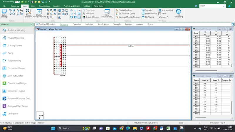
From above fig
Create a mess for deck slab with thickness of 0.225 m as shown in the fig.
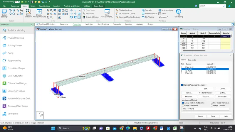
Fig-3 above
From above fig span length is 45 m and 3 circular column with dia 1.065 m are made at equal distance of 3.6 m for Abutments (A1 and A2) as shown in fig.
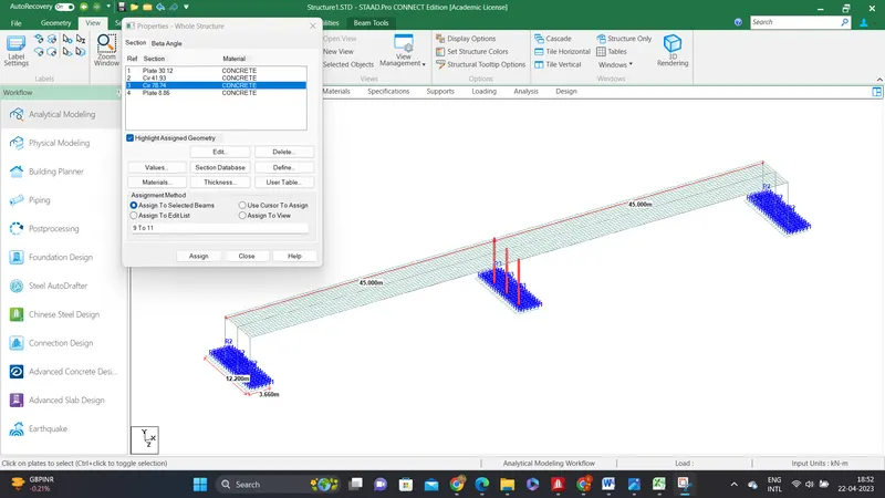
Fig-4 above
2m dia circular columnn are made at equal distance of 3.6 m for the pier as shown in the fig-4.
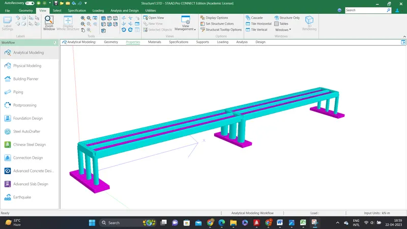
Fig-5 above
The three dimesional view of the entire bridge as shown in the fig-5.
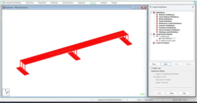
Fig-6 above
Add a load cases of Dead Load for self weight (-1 in y-direction) as shown fig-6.
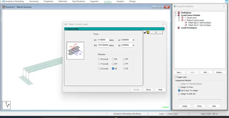
Fig-7 above
Add new load case water current Load for Pier and assigned 1937KN/m2 as a trapziodal loadings as shown fig-7.
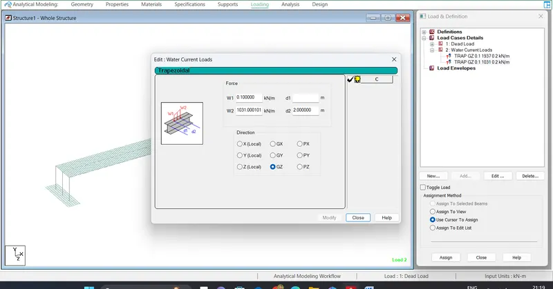
Fig-8 above
Add new load case water current Load for Abutments 1031 KN/m2 as a trapziodal loadings as shown fig-8.
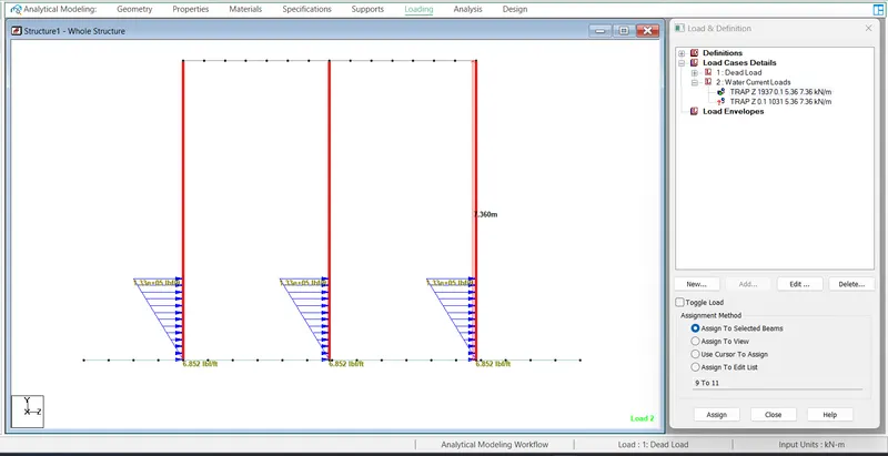
Fig-9 above
The Trapizoidal load 1937 KN/M2 at the Height of 2 m from the foundation level has been applied on the pier as per given data.
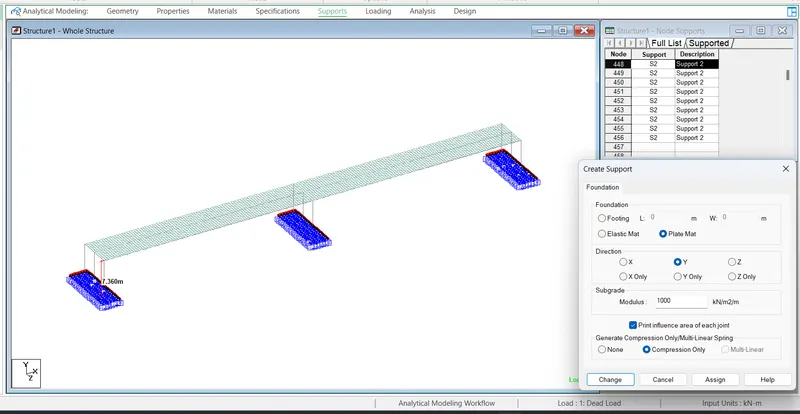
Fig-10 above.
Add supports for the columns as a founation for both pier and abutments with sub grade modulus of 1000 KN/M2/m as shown fig
Assumed Safe Bearing capacity (SBC) = 50 KN/m2
and Allowable settlement 0.05m (50mm)
Subgrade modulus =50/0.05 =1000 KN/m2/m.
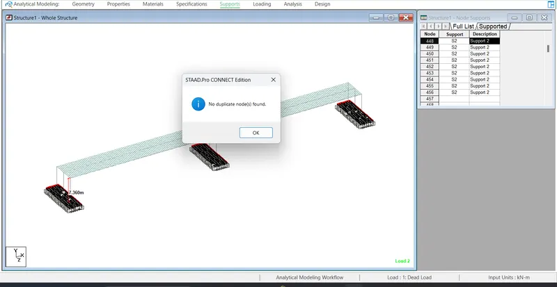
Fig-11 above
Before going to Analysis important ckecks have been done as shown in fig-11
No duplicate nodes are found.
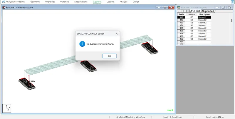
Fig-12 above
No dupilcate members are found.
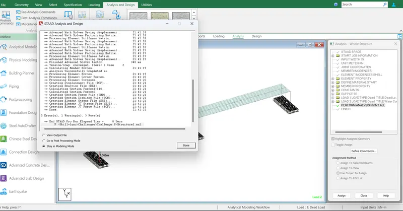
Fig-13 above
Analysis has been completed successfully with Zero Errors as shown in the fig-13 and can go to post processing mode for results.
RESULTS :-
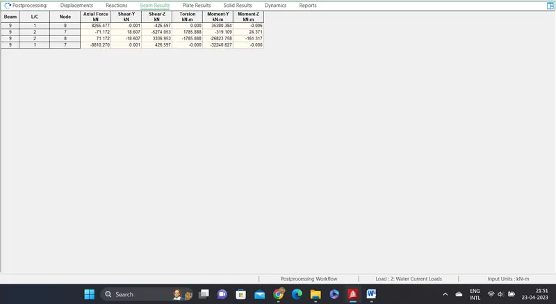
Fig-14 above
Maximum forces in the Pier Column
Maximum Axial force =8265 KN
Maximum BM=35380 KN-m
Maximum SF=5274 KN.
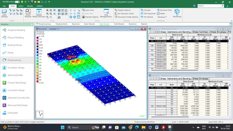
Plate Results
Maximum stress 5.44 KN/m2/m as shown fig..