Week 7 Challenge
Modelling of Structure in STAAD Pro
1. Modelling of a structure exercise
Model a structure with following details
- Bay spacing 5 m
- Span of Truss 30 m
- Shape of Truss – Pratt Truss
- Slope of truss 20 degree
- Height of the column 15 m
- Floor Beams at 5 m from base
- Secondary beams at 1.5 c/c
- Length of the building 50 m
- Column Supporting Floor Beam @ 6 m c/c Along the frame
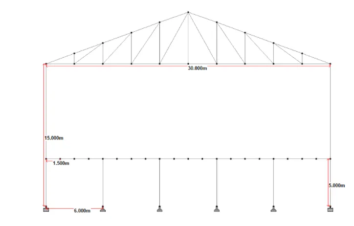
Ans:
Aim: To model a tructure in STAAD for given details
Procedure:
Step 1: Go to STADD PRO software and go to new option,select the folder where you want to save the file and fill the details and select the metric units.Then,click the create option to start the modelling
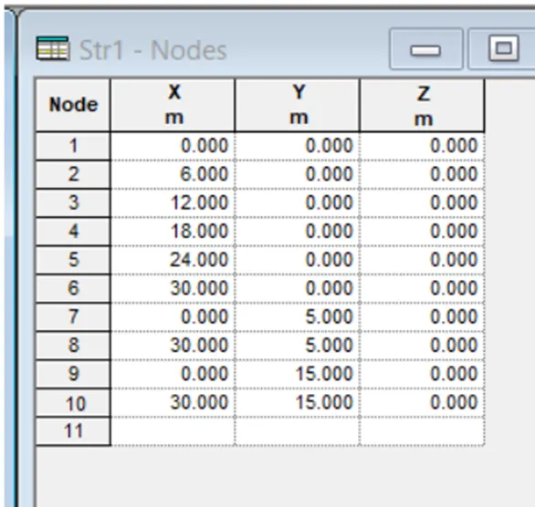
Step 2: Add the nodes to create the basic main frame structure
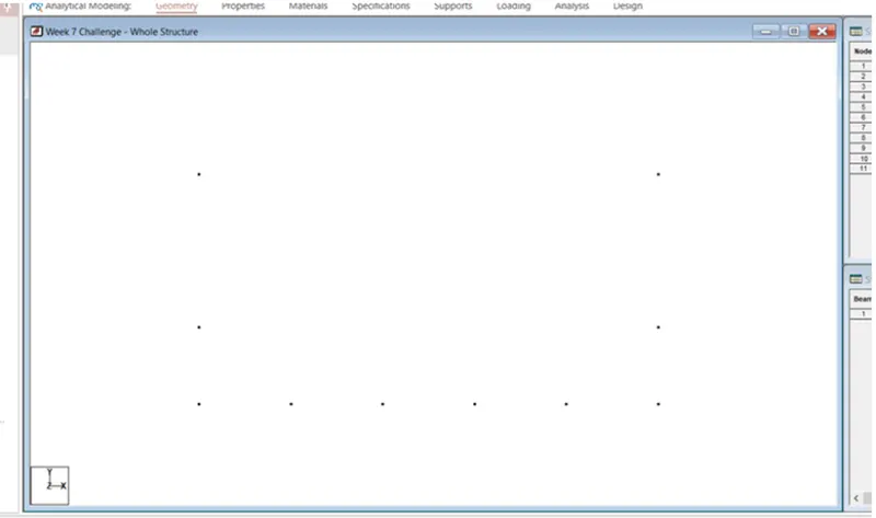
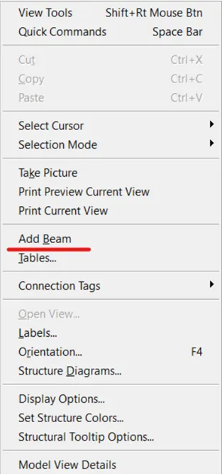
Step 3: Right click on the screen and select add beam option ,now select the nodes to add the beams between the nodes
Step 4: Add nodes to create floor beam using insert nodes options
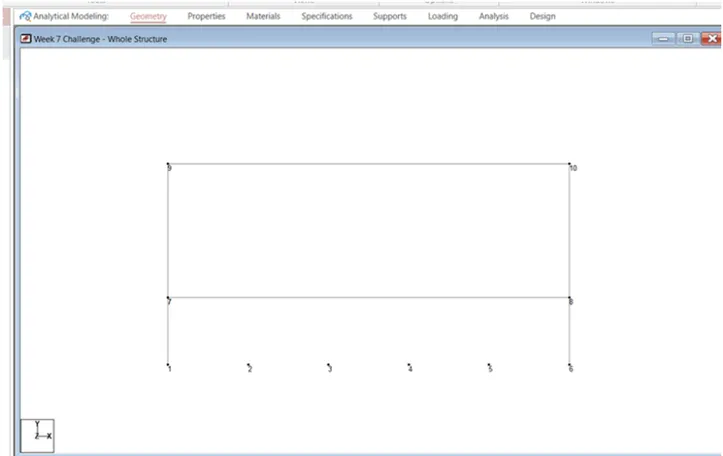
Step 5: Select the beam,right click and select insert node option ,a dialog box will appear,fill the distance at which we want to create the nodes and value on number of nodes to inserted
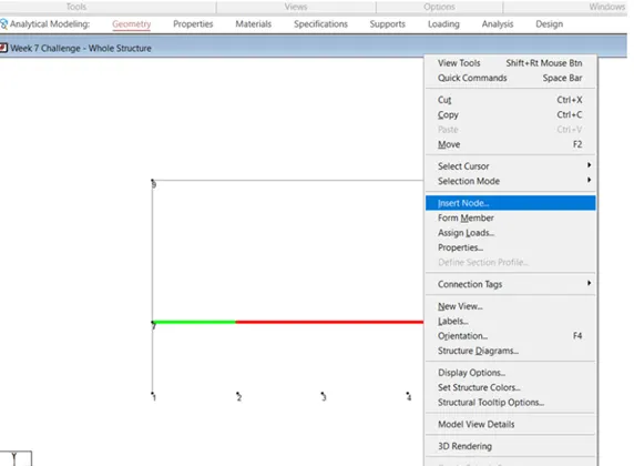
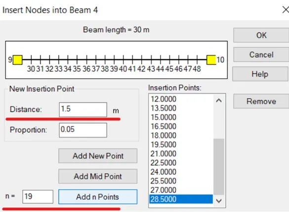
Step 6: Go to add beam option to create columns between the floor beam and supports
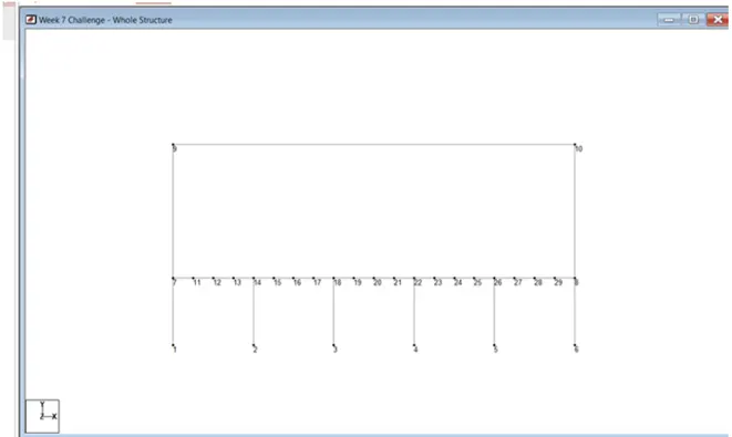
Step 7:Go to the geometry tab and select structure wizard to create a roof truss
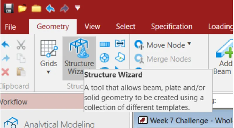
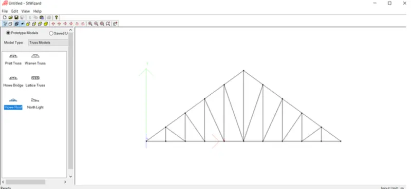
Step 8: Select the roof truss that we want in our model and fill the details of the truss
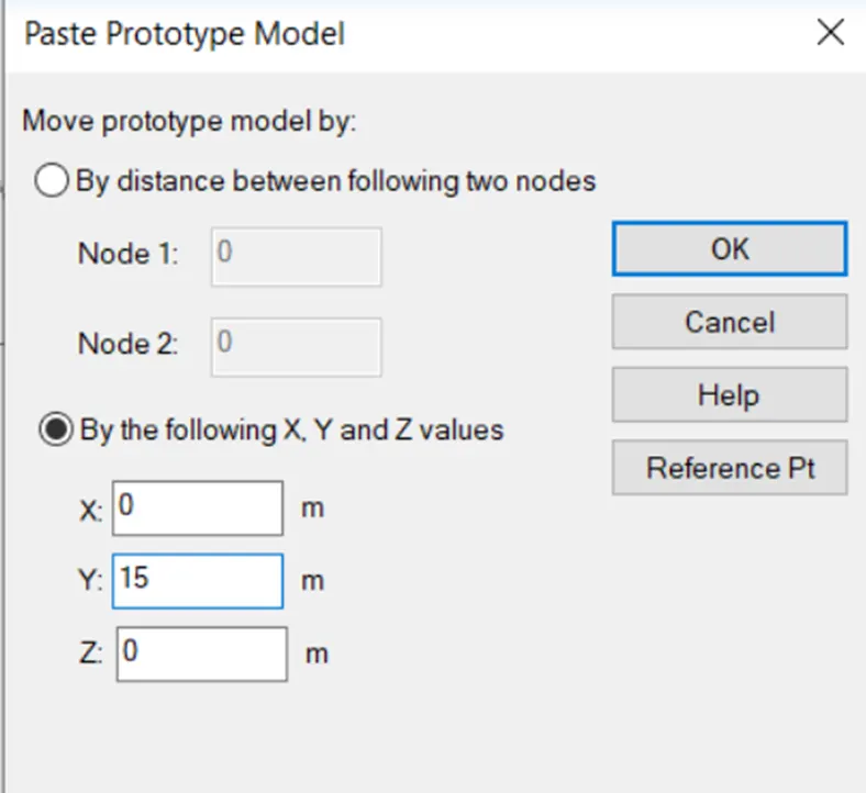
Step 9: Close the structure wizard and click yes to merge the roof truss in our model.Fill the coordinates the node where you want to add the roof truss.
Step 10:Go to translation repeat option to create the coppy of the frame along the length of the building and fill the required details in the given data
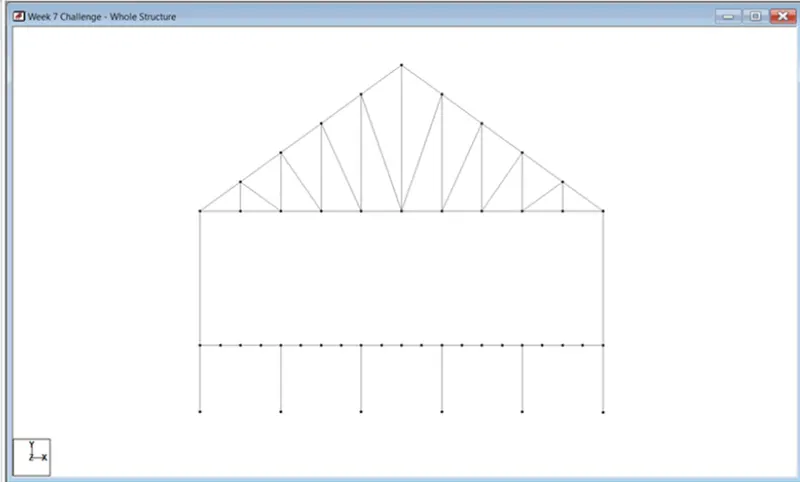
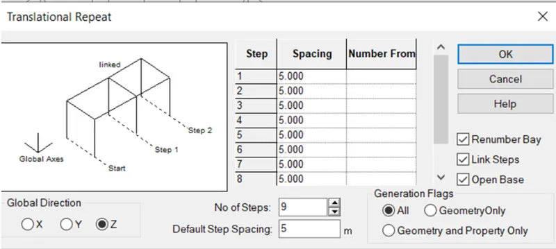
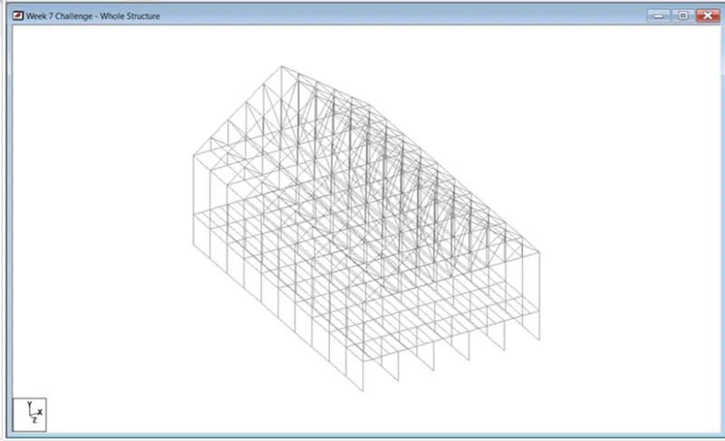
Result :Model has been successfully created
Q2. Applying Specification and member property for modelled structure
Apply beam steel specification as mentioned below.
- Columns - ISMB 500
- Truss -Top & Bottom chord – ISA 110x110x12, Diagonal member – ISA 75x75x8
- Purlins – ISMC 150
- Tie Beam – ISA 120x120x10
- Floor Primary beams – ISMB 300
- Secondary beams - ISMC 150
- Floor beam supporting columns – ISMB 300
- Assume bottom of the main column as Fixed support & intermediate floor beam supporting column as pinned
- Orient the Angle sections by applying Beta angle
Ans:
Aim: To apply specification and member property for modelled structure as per given specifications
Procedure:
Step 1: Select the structural elements that we want to add the specification and properties
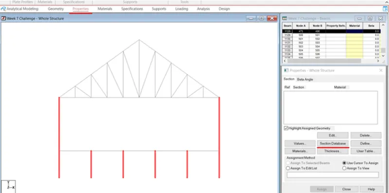
Step 2 : Go to properties and select the required section from database
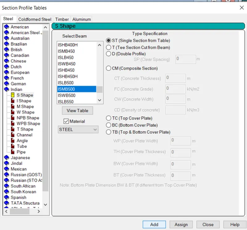
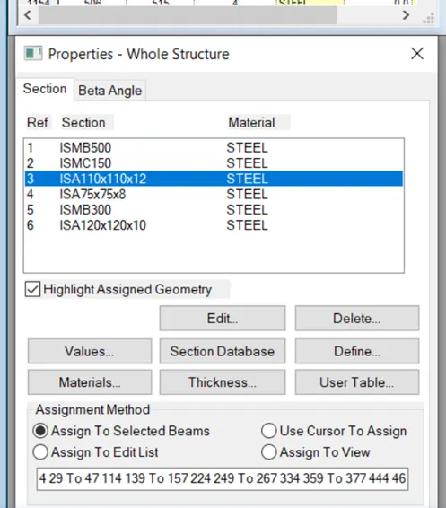
Step 3: Select the country and select the required location .add the sections that are going to be used in the model.Assign the properties to the structural elements by selecting the mode of assignment and clicking on assign
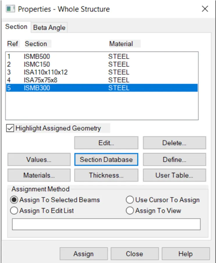
Step 4: Similarly apply the properties to the other structural elements
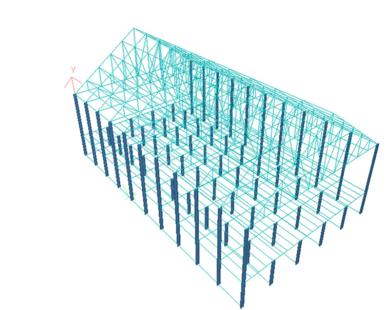
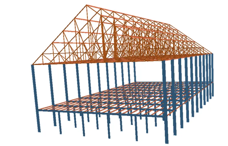
Step 5: Go to support option and select the nodes and click on create option to create the required type of support that we want
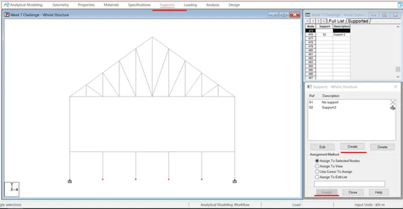
Step 6: Supports to column base support has been added.
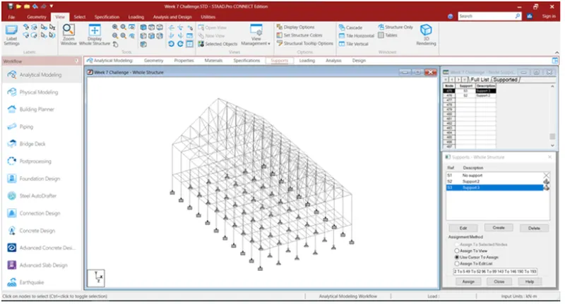
Step 7: Go to property option ,select the angle that we want to orient and click on beta angle,enter the value of beta angle to orient the angle sections
Step 8: Go to 3D rendering
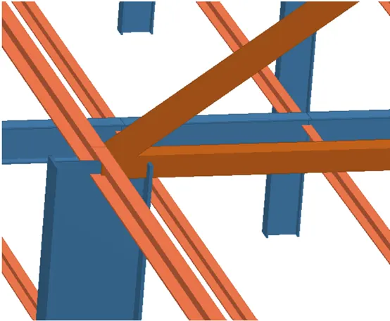
Result : All the properties of the structural element has been assigned and angle section has been properly oriented using beta angle option.
Q3)Creating a group exercise.
Form group for following members
- External column
- Internal columns
- Roof Frames
- Top chord of the Truss
- Primary Beams
- Secondary Beams
Ans:
Aim: To form group for following members
- External column
- Internal columns
- Roof Frames
- Top chord of the Truss
- Primary Beams
- Secondary Beams
Procedure :
Step 1: Go to select tab and click on group option,window pops up create the group names and select type as beam.
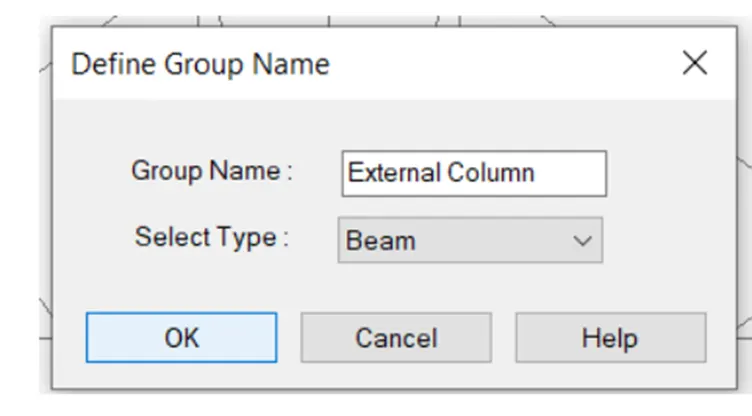
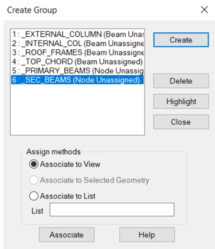
Step 2: Select the structural elements and associate it with the respective group
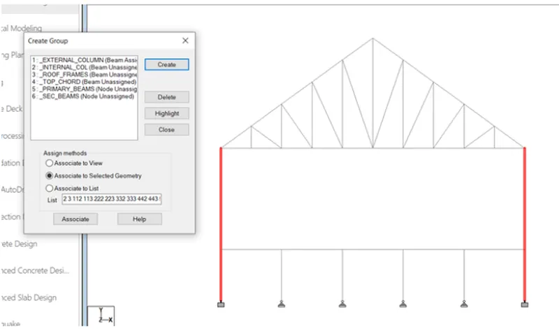
Step 3:Select the other structural elements and associate them respective groups.After all the grouping is done,in the create group dialog box assigned will be mentioned in the bracket.
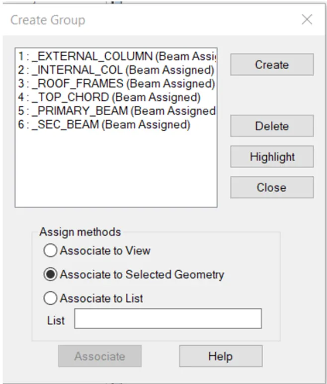
Result: All the respective structural elements have been associated with their respectiv