Week 7 Challenge
AIM and INTRODUCTION :
- To calculate the water current load for the given bridge and apply the calculated loads in the staad pro..
- The water current forces are the forces caused by the ocean currents.
- Deep ocean currents are driven by density and temperature gradient.
- The major ocean currents are
> North Equatorial currents.
> Atlantic currents.
> North Pacific currents.
> South Indian currents.
- Water current loads are calculated as per IRC as follows.
- P= 52 * K * V * V
- P is the pressure intensity due to water current(kg/m^2).
- v maximum velocity of water current(m/s).
- where K is constant, varies accordingly with shape.
- The maximum velocity, V= (2)^0.5 * Vmean= 1.414 * Vmean
- The High flood level is above 2m from the foundation level.
- The mean velocity is given as 3m/s
PROCEDURE :
- First, we need to calculate the water current load,
P= 52 * K * V * V
V= 1.414 * 3= 4.242 m/s
K= 0.66 (We assume cicular pier)
P= 52 * 0.66 * 4.242 * 4.242
P= 617.57 KN/m^2
- We assume pier size as (1*1)m, Udl load = 617.57 * 1= 617.57 KN/m.
- So we need to apply the load of 617.57 KN/m udl load to the pier as a water current load.
- Now, we generate a model in staad pro, applying the load and analyze it.
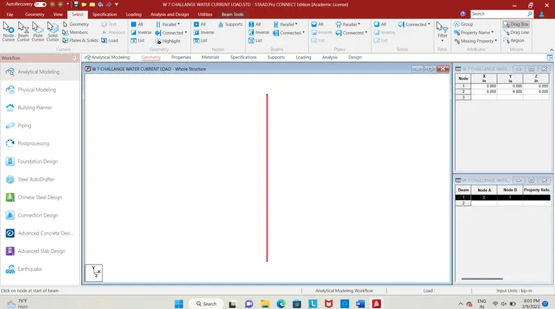
Fig. 1
- First we enter the nodes (0,0,0), (0,7,0) , by using add beam command connect the nodes. Pier is formed of height 6m.
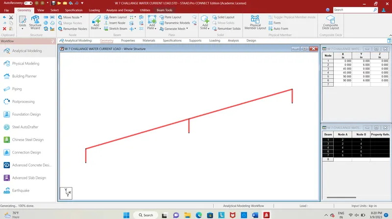
Fig. 2
- By selecting pier and using translational repeat, no. of step=2, spacing=22.5m in X-direction. Longitudinal section of bridge is formed having span = 45m.
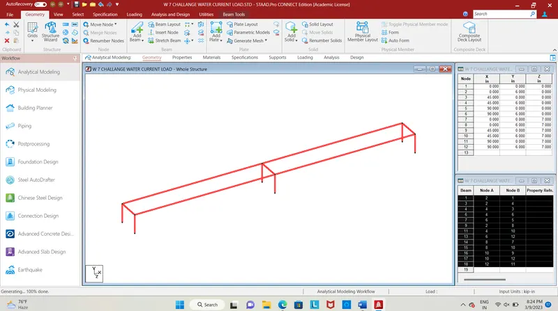
Fig. 3
- By translational repeat in X-direction at spacing=7m, no. of step=1, bridge structure is formed.
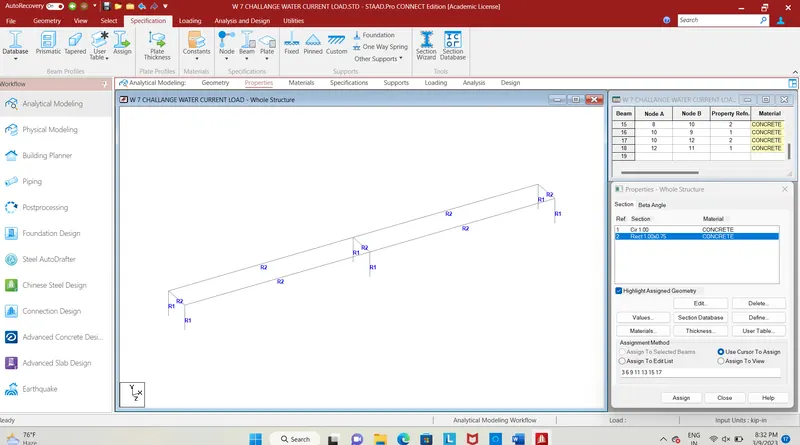
Fig. 4
- Providing property to the piers as rectangular section of 1.0m * 1.0m, cross beam and main beam as (0.75*1.0)m by using specification and prismatic bar, providing dimension.
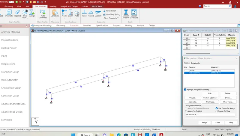
Fig. 5
- Providing fixed support to the pier, by selecting nodes and go to the specification, use fixed support bar and then assign it.
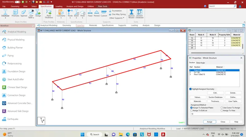
Fig. 6
- Add a plate thickness of 200mm and select the corner node of deck to assign the geometry to the selected deck plates, Thus the sections are assigned with geometrical properties.
- Now we provide water current loads to the structure.
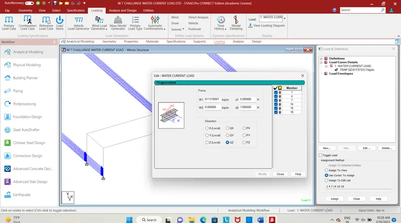
Fig. 7
- In the load case details click add, enter the title as water current loads, select add click the member loads, in that member loads click on trapezoidal load.
- Enter the calculated force values, and enter the height up to which the load has been applied, the load will be acting for a height of 2.0m.
- W1= 617.57 KN/m, W2= 0, d1=5.0m, and d2= 7.0m in GZ direction.
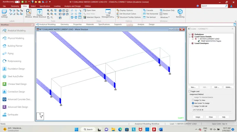
Fig. 8
- The load is applied in the z-direction, at the calculated height, next step is to analyse the structure, use the run analysis command to analyze the structure
RESULT :
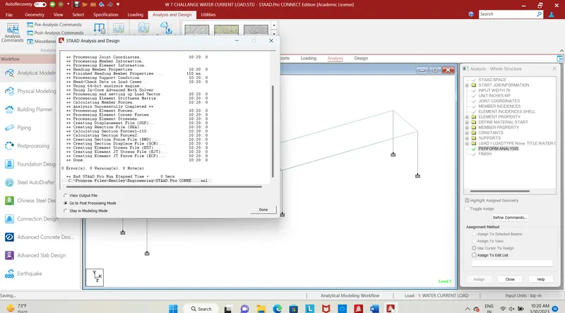
Fig. 9
- Enter into post-processing mode, to analyse the structural behaviour of the bridge.
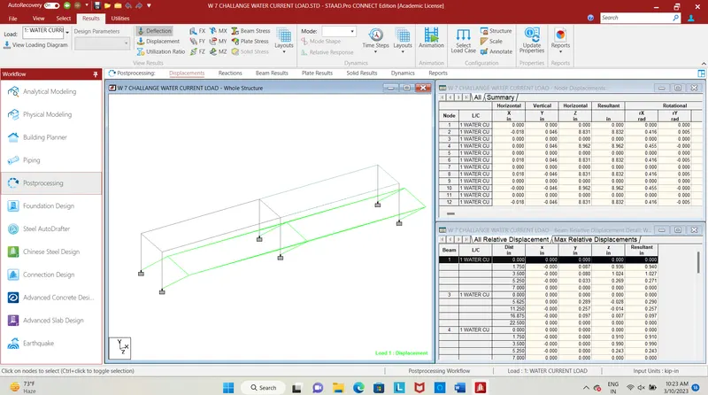
Fig. 10
- The fig shows the deflection pattern of bridge structure due to water current loads.
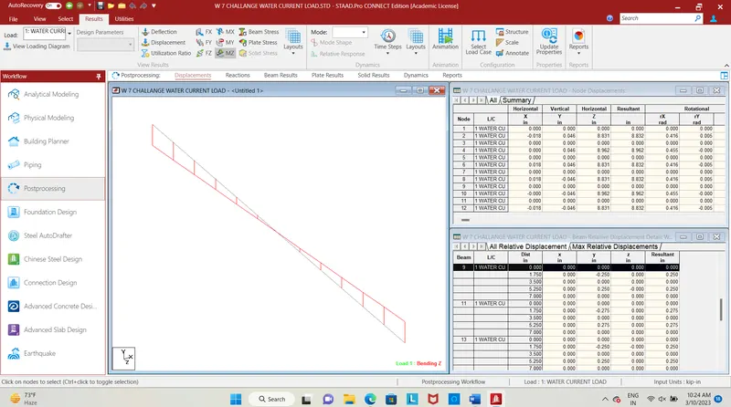
Fig. 11
- The fig shows the bending diagram in cross beam in Mz.
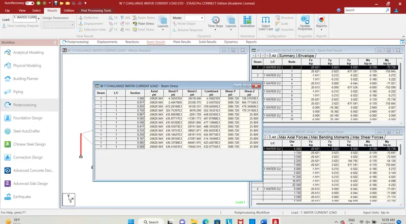
Fig. 12
- The report says the bending stress in pier in Mz direction from high to low.
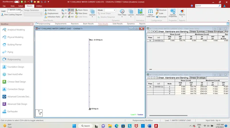
Fig. 13
- The fig shows the bending in pier due to Mx.
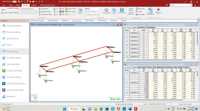
Fig. 14
- The beam results have been shown for pier click on annotate, select beam click on beam ends, select My.
- Hence the water current load has been calculated and applied for the designed bridge using staad pro.