Week 7- Base Unit Design Challenges 2
BIW fixture assembly:
- The four clamp units arrests the translation about Z-axis and the rotational movement about Y-axis and X-axis.
- The Two Pin units around the center of component arrests the translation about X-axis and Y-axis as well as the rotational movement about Z-axis
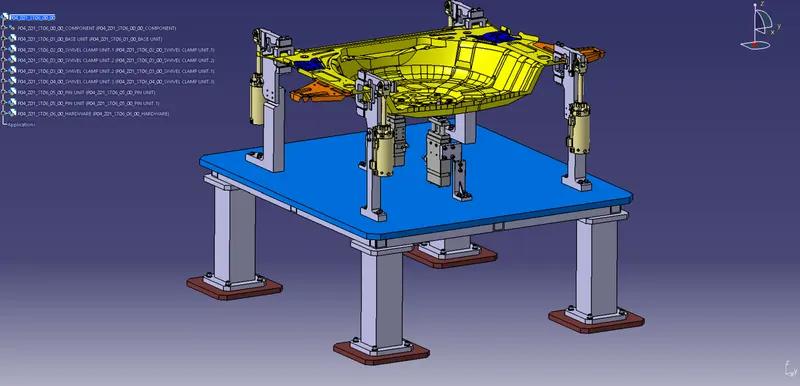 Image.1
NOTE:
- The orientation of axis system is shown in Fig.1.
- The clamp units and pin units are that of previous projects.
- In all images the sheet metal component (Yellow coloured) is shown for contextual purpose.
BASE UNIT DESIGN:
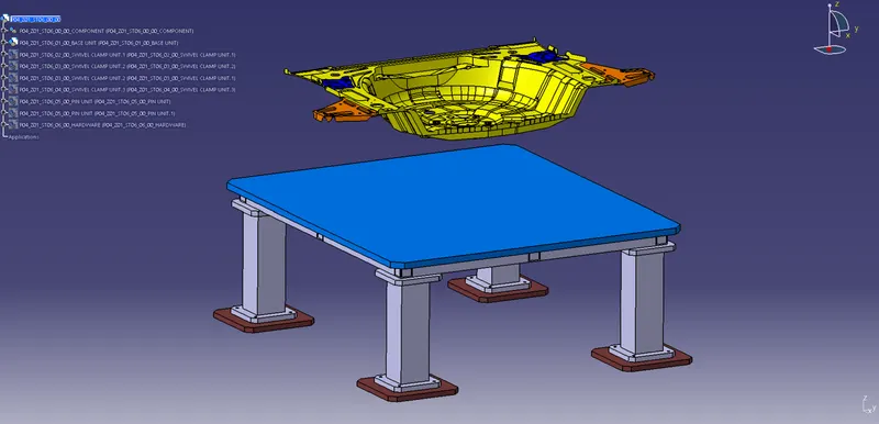 Fig.2
Fig.2
- BASE PLATE:
A 25mm thick machined plate onto which all the clamp units and pin units are mounted as shown in Fig.2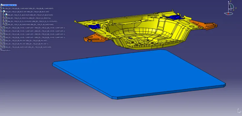 Fig.3
Fig.3 - PEDESTAL:
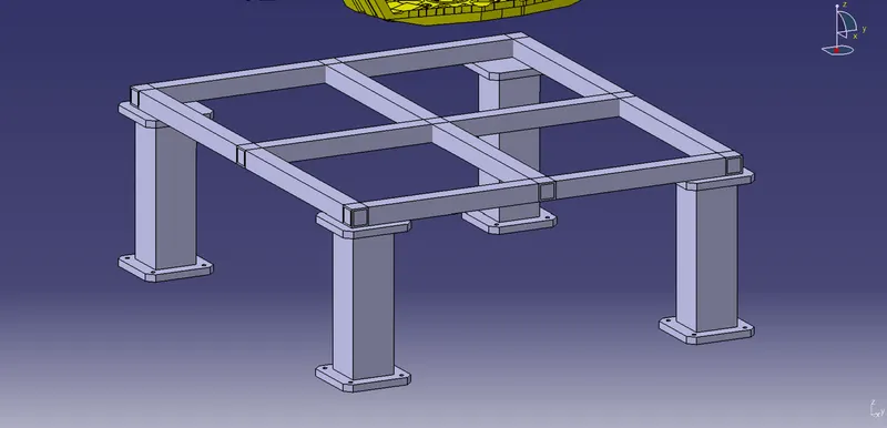 Fig.4
Fig.4
- Frame: A square tube cross-section structure for supporting base plate and avoid any bending due to weight of various units above it. (Fig.5)
Square tube Size: 50mmx50mm having 5mm thickness is used in two size of 1300mm and 1150mm length (3 each used).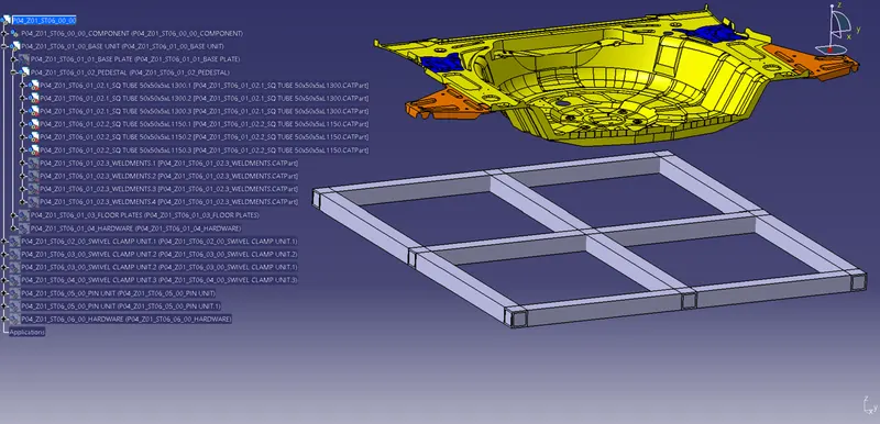 Fig.5
Fig.5 - Pillar Structure: A square tube cross-section structure consisting thick plate on either side. (shown in Fig.6)
Square tube Size: 120mm x 120mm with 10mm thickness and 400mm length. (shown in Fig.7)
Plate Size: 200mm x 200mm with 20mm thickness.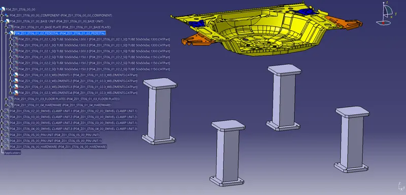 Fig.6
Fig.6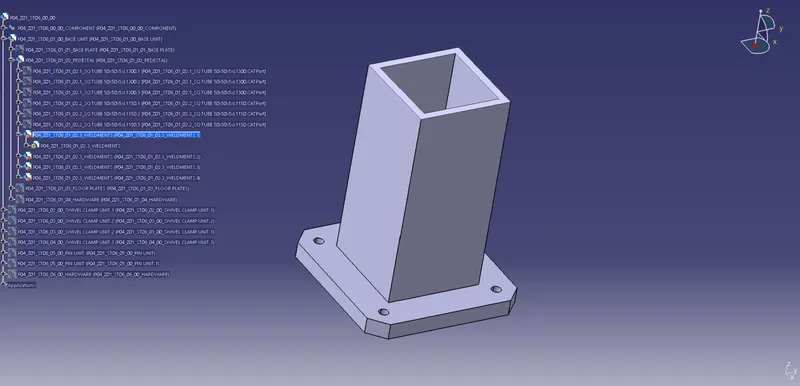 Fig.7
Fig.7
- Frame: A square tube cross-section structure for supporting base plate and avoid any bending due to weight of various units above it. (Fig.5)
- FLOOR PLATES: The part which connects pedestal and base plate to the floor area. These are 20mm thick machined plates employed so that pedestal body could be screwed onto it. (shown in Fig.8)
Size: 300mm x 300mm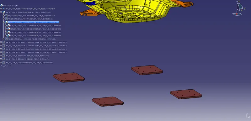 Fig.8
Fig.8