Week 7- Base Unit Design Challenges 2
AIM:
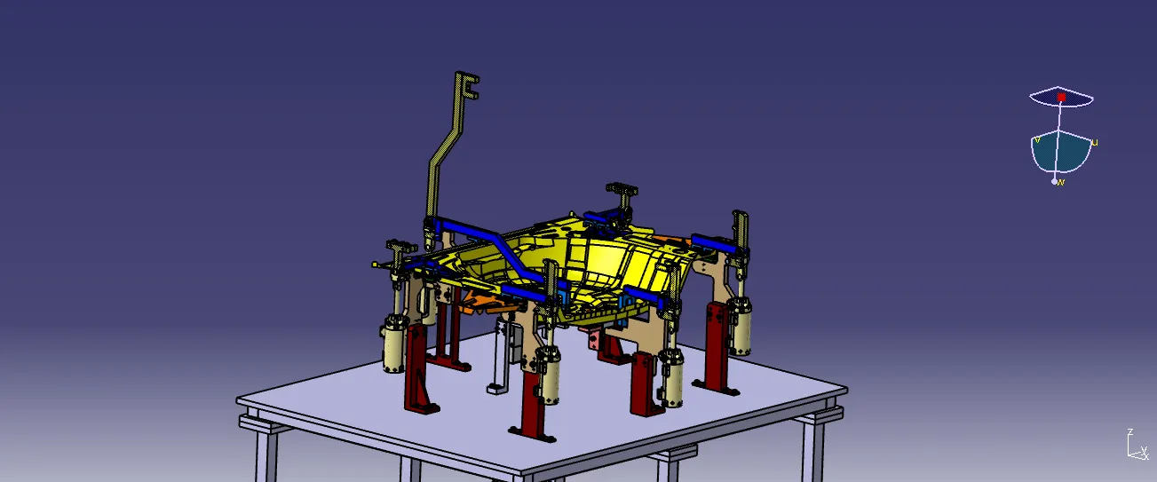
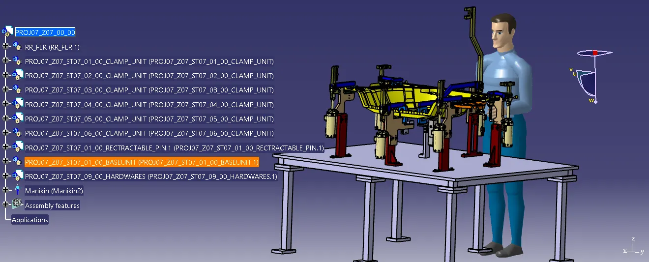
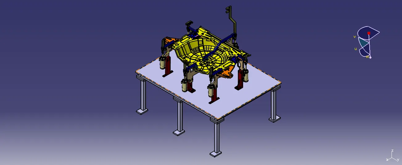
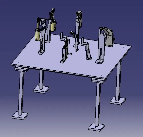
To design a base unit with all weldments for the given Car Panel & Design all the other remaining Units required for this Fixture assembly.
OBJECTIVE:
Design a Base Unit with all weldments for the given Car Panel. And Design all the necessary Units required for the Fixture design
. BASE UNIT:
A unit used to mount all unit over it like a clamp, pin likewise.
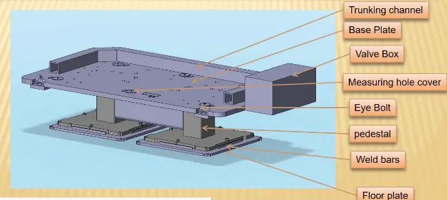
Also, it will rest subpart of the main unit like the pneumatic valve box which is used to supply air to the inlet of all pneumatic cylinders. Trunking cable path is also supported on the base unit.
It has trunking channel base plate, valve box, measuring hole cover, eye bolt, pedestal weld bars, floor plate.etc
DIFFERENT PARTS OF BASE UNIT:
Base Plate:
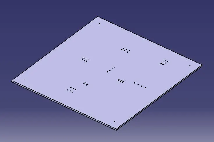
• The base plate is a plate of 25 mm to 40 mm thickness. The base plate has no of holes drilled on it which will act as mounting points for clamp unit, pin unit and so on.
Pedestal:
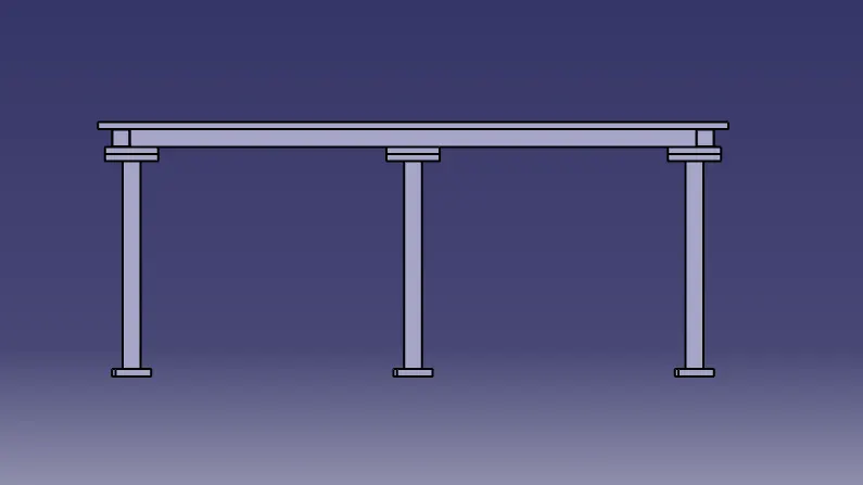
it is used to connect the base plate with a floor plate.
• The pedestal can be a standard part or a make part, depending on the size and height of the fixture.
• Standard pedestals are available in different heights.
Pedestals are also available in different inclinations.
• Depending on the size of the base plate, the number of a pedestal for a fixture can vary for load distribution.
Trucking channel:
Trunking Channel is a duct that carries all the electrical and pneumatic connections(wires and pipes) for units of the tool.
It has a thickness of few millimetres.
Trunking Channel image
Valve box: -
- Valve Box is a standard part which contains all the valves for the pneumatic units.
Eyebolt: -
- Eye Bolts are the bolts that are used to lift the fixture for transportation by inserting hooks into them.
- For example, we usually use M20 bolts that are bolted on the base plate.
- Used for transportation purpose, sometimes forklift holes will be provided.
Eyebolts M20 is shown above
Floor Plate:
- They are also known as foundation plate. They are grounded by using a fixed bolt.
- 10 mm clearance should be given between pedestal base plate and floor plate.
- Weld bars need to use after the levelling is done by levelling screw.
- Weldbars are steel plates along the sides of the base plate of a pedestal.
- Weld bars are used to position the positions permanently.
POINTS CONSIDERATION DURING DESIGNING THE BASE UNIT:
- It depends on the nature of the manual or robotic welding fixture.
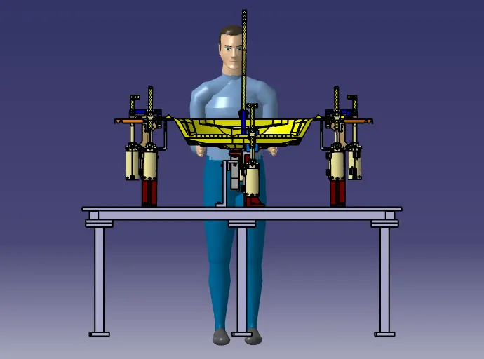
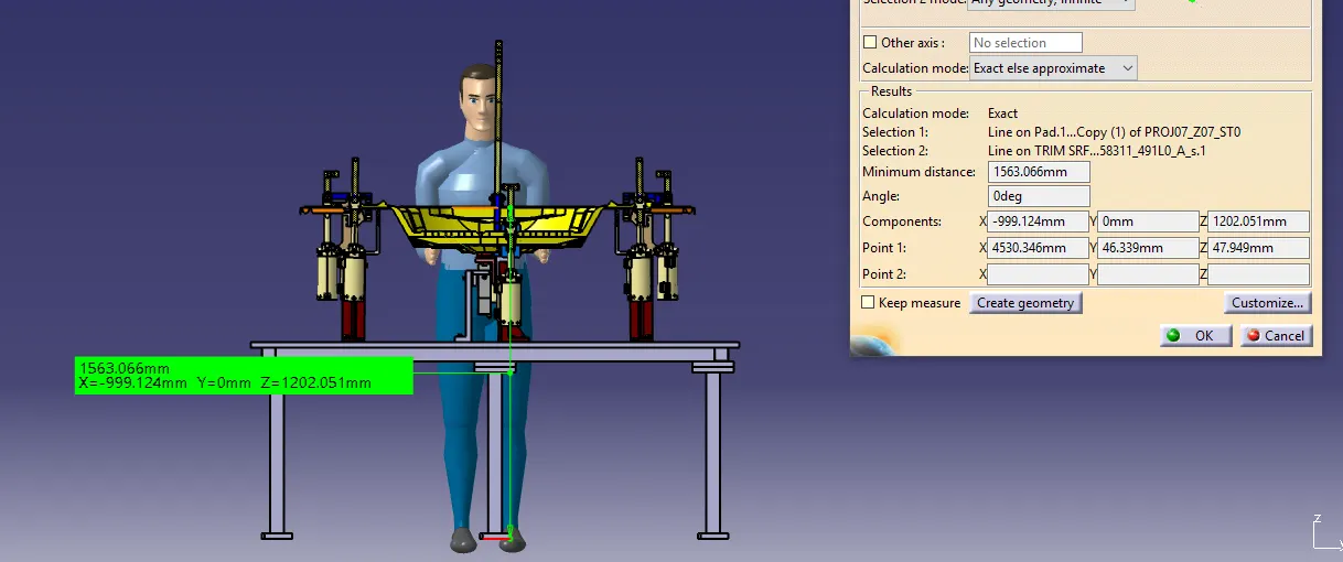
- For manual fixture we need to consider the working height 850-1100 mm, depending upon the working height of the worker standard of a specific country will apply( In few countries human height is higher or lower e.g. US, Japan).
- here I design base unit with around 1563 mm working height.
2. As a designer its is important to know how big base plate or bigger base welded structure will be handled during the fabrication and handling process. Special care needs to be taken care of flatness if the base size is very long.
3. Depending upon the weight eyebolt size are selected for lifting holes on the base plate.
- Generally, 4 eye bolt provision is made.
- Mostly M20 is used.
- You also need to select the location of eye bolt considering the rope/ belts used while shifting the structure or complete fixture are not damaging any units(rest, clamp or location units) nearby.
Eyebolts M20 is shown above
- Depending upon the component size and weight of the total units you can decide whether you need a fabricated base or just plate.
- Mostly fabricated bases are used made of square or rectangular tube with the plate.
- Square tube of 50x50x2 is used for base fabricated. and square tube of 80x80x2 is used for support welded structure.
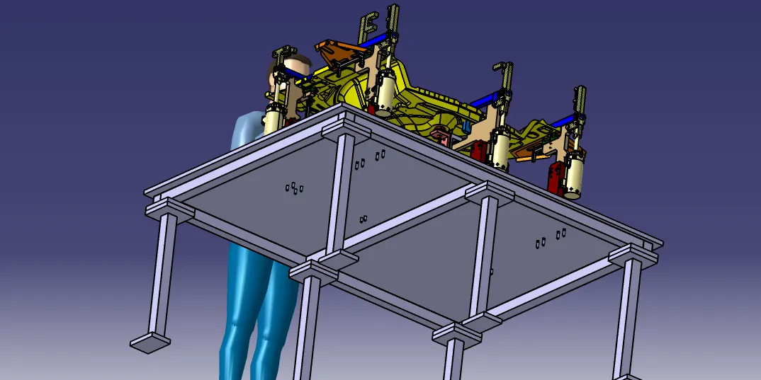
5. The base unit of the fixture must be strong enough so that deflection of the fixture is as minimum as possible. This deflection of a fixture is caused because of forces of welding, clamping of the workpiece.
6 The Base unit of the fixture should have the mass to prevent vibration and chatter.
7 The base unit may be built from simple sections so that other units may be fastened with screws or welded whenever necessary. Those parts of the fixture that remain permanently with the fixture may be welded. Those parts that need frequent changing may be held with the screws.
- The permanent parts of the base units are welded together & other parts have the facility to be fastened to the base unit. The base plate is designed to assemble these units without being fallen to each other.
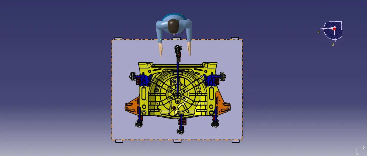
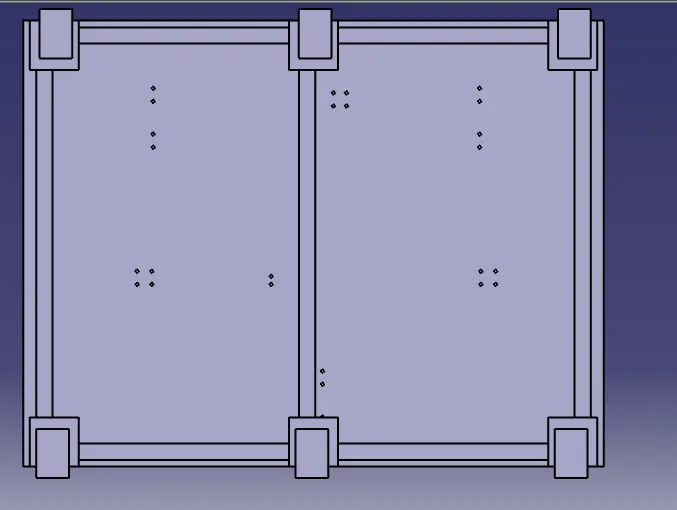
8 The base unit should cover all the units with its outer periphery including the opening.
- from the top view, enough space is provided at all boundary.
USE 3-2-1 PRINCIPLE:
- The best & most cost-effective method of part location is referred to as the 3-2-1 method.
- All Fixtures work on 3-2-1 principle.
- Require 3 Minimum: Three locator blocks to establish the part plane. Three locators or supports are placed under the workpiece. Three locators are usually positioned at the primary locating surface.
- Clamp unit restricts 2 axial movements upward and downward. and other 2 Pin unit restricts radial movement.
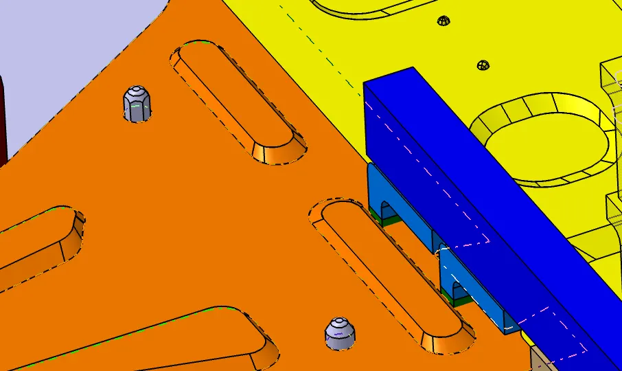
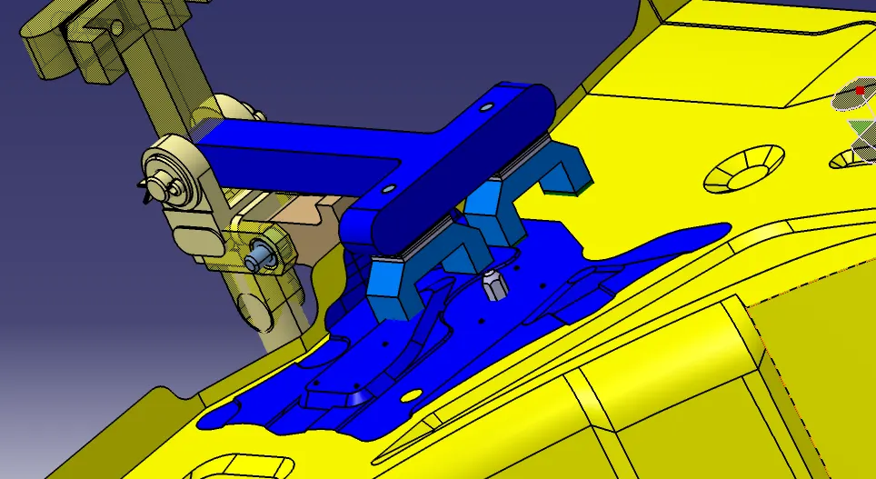
As by 3-2-1 method, by introducing a minimum of 1 clamping & 2 pin unit will restrict 6 degrees of freedom (DOF) [Two axial movements & four radial movement].
- Structuring a design tree implies a process where all the assemblies & parts are named in a specific standard. Different customers have a different set of standards to structure a design tree.
- It is an important process which helps us to identify a specific part or assembly as to which project, tool/unit, it belongs to.
- This helps us to avoid the errors during design study, manufacturing, assembly, inspection, etc.
- If the parts or assemblies are not named properly or the design tree is not structured properly, it will create confusion to understand the design & may create major possibilities of making an error.
- The naming of a fixture or a unit or a part gives the information as to which project or zone or assembly do they belong.
- It can help us to identify the number of items of the same types or different types that are being used in the assembly.
- While start designing a fixture, the first unit will be the base unit.
- In the structure tree, all the manufacturing parts should be first and the standard parts should be at the last.
- Structure tree helps to study or understand the parts in the assemblies easily.
Conclusion:
Thus the design a base unit with all weldments for the given Car Panel & Design all the other remaining Units required for this Fixture assembly was done.