Week 7- Base Unit Design Challenges 2
BASE UNIT DESIGN
AIM
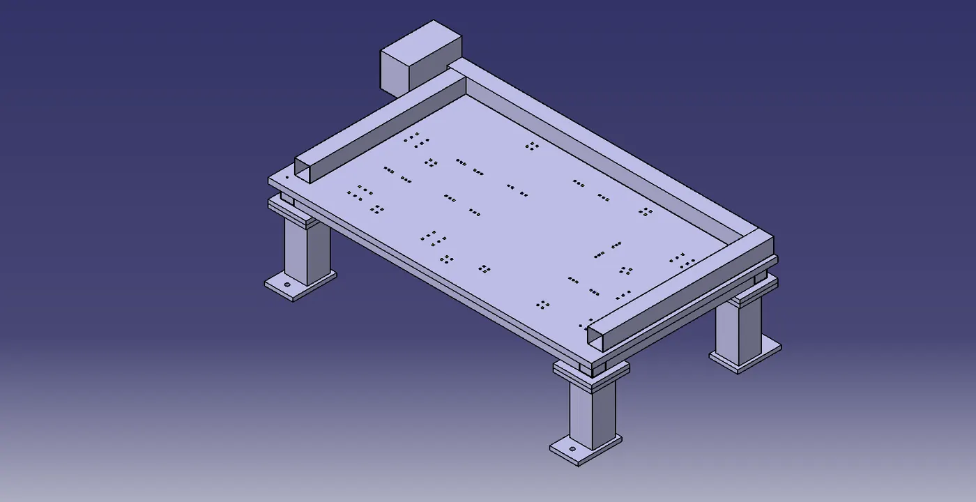
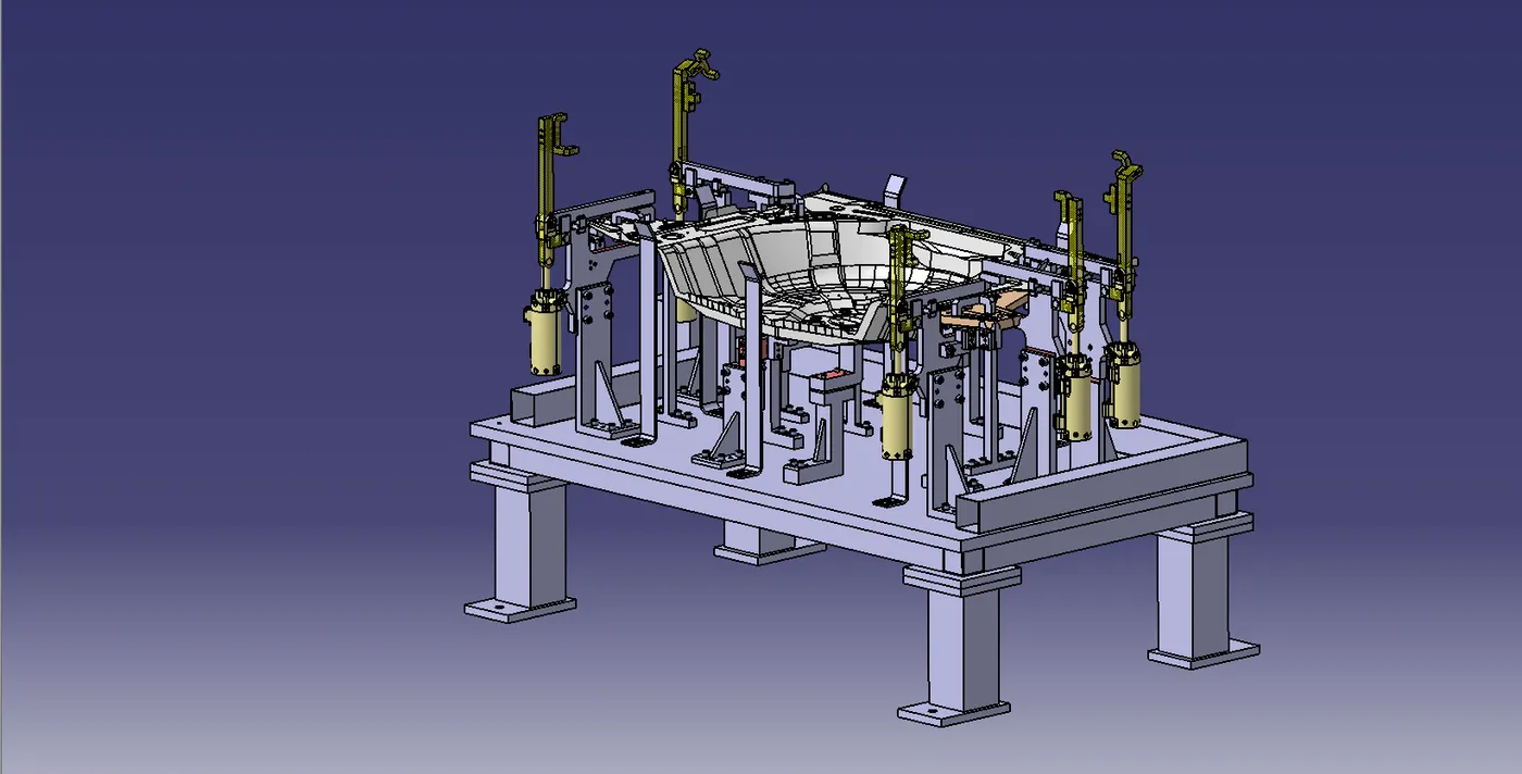
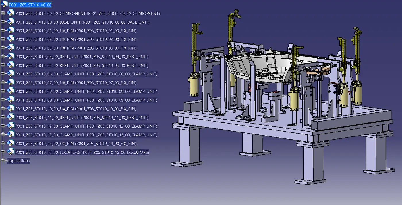
Design a base unit for the units made for the aforementioned challenges, including all the Weldments for the specified car panel. Create the entire fixture assembly using the units that were created for the earlier challenges. Verify that the 3-2-1 concept is fully applied to each of the five panels listed in the CAD data.
INTRODUCTION
A base unit is intended to hold all of the tool's other units, such as the clamp, pin, rest, and other units. It can also hold other components that are required for the tool, such as the pneumatic valve box and the trunking cable path. Since every other component of the fixture is positioned over the base unit, it is the essential part of the fixture. The panel's design differs from the base unit's. Clamp system design, location system design, etc.
Parts of the Base Unit
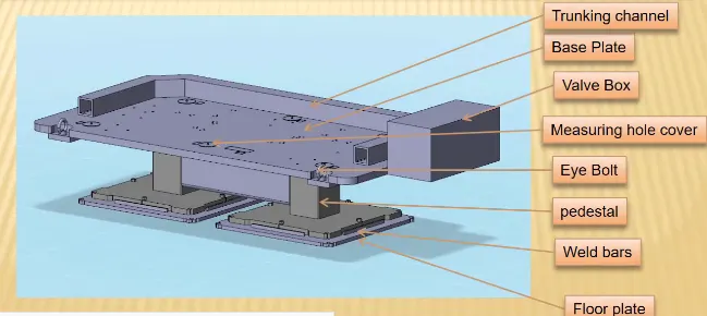
Base plate
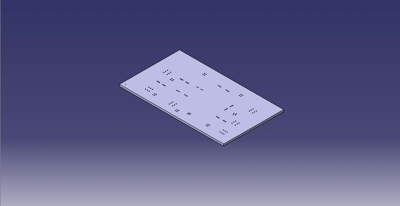
Numerous holes have been bored into the base plate to serve as mounting locations for clamp, pin, and other units.
Pedestal
It is employed to join a floor plate to the base plate. Depending on the fixture's height and size, the pedestal may be a make-or-standard element. Standard pedestals come in a variety of slopes. Additionally, pedestals come in a variety of slopes. For load distribution, the number of pedestals for a fixture might vary based on the size of the base plate.
Trucking channel
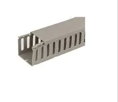
The Trucking Channel is a conduit that transports all of the tool's electrical and pneumatic connections, including pipes and wires. It is one millimeters thick.
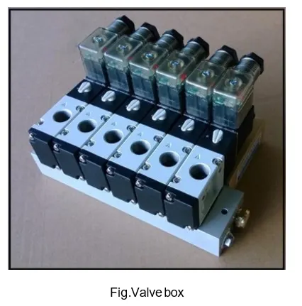
Valve box
A basic component that houses every valve for the pneumatic units is the valve box. The box that contains various solenoid valves is called a valve box. The air pressure that is supplied to the pneumatic fittings causes them to function. Thus, this valve box is used to arrange the air pressure inlet and outlet. All of the pressure input cables that supply the fixture's pneumatic components are housed in the trunking channel, which also shields them from harm while operation is underway.
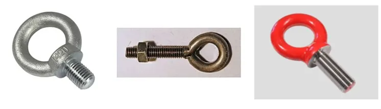
Eyebolt
By putting hooks into them, eye bolts are utilized to raise the fixture for transportation. For instance, M20 bolts that are fastened to the base plate are what we typically use. Sometimes forklift holes will be made for hauling purposes.
Floor plate
Another name for them is foundation plates. A fixed bolt is used to ground them. There should be 10 mm of space between the floor plate and pedestal base plate. After levelling with a levelling screw, weld bars must be used. Steel plates that run along the sides of a pedestal's base plate are called welded bars. The positions are fixed in place with the help of weld bars.
Fundamentals of Base plate Design
- Knowing how large base plates or larger base welded structures will be handled during the manufacturing and handling process is crucial for designers. If the base size is very long, extra attention must be paid to flatness.
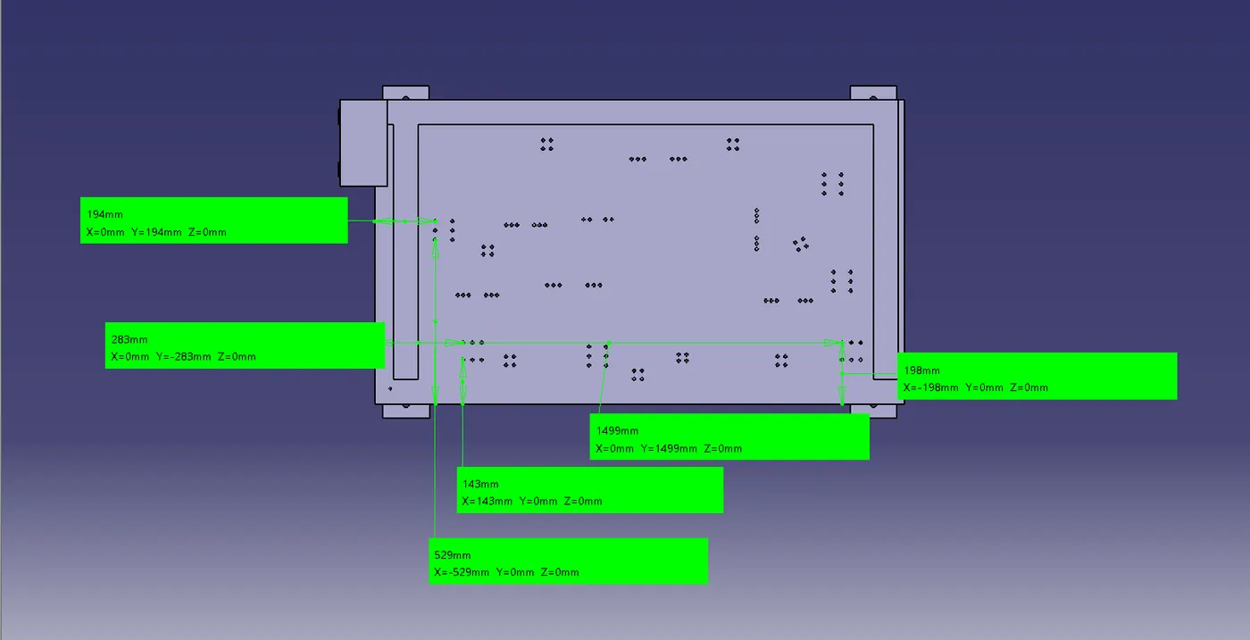
- A base plate's dimensions should encompass every unit's outer edge, including the aperture. It is preferable to design a base plate using BCS coordinates.
- Drilling datum or measurement holes in a base plate should generally follow a 1000 mm pitch.
- The size of the base plate determines how many datum holes are needed.
- In terms of 50 x 100, datum holes should be bored at nominal coordinate values. For example, X=IOO, Y 600, Z-250 (mostly).
- Drilling datum holes should be done 100 mm apart from other units.
- Cover plates should be used to cover the datum holes.
- The eye bolt size for lifting holes on the base plate is chosen based on the weight. Typically, provisions are given for four-eye bolts. Additionally, you must choose the eye bolt location so that the ropes or belts used to move the structure or entire fixture do not damage any neighboring units (such as rest, clamp, or location units).
- You can determine whether you require a manufactured base or only a plate based on the component size and weight of the entire quantity. The plate is typically used with constructed bases composed of square or rectangular tubes.
- The majority of OEMs create four dowel holes at each corner and label the X, Y, and Z coordinates of the dowel holes with a tiny metal plate. Few OEMs use the 500 mm hole spacing technique if the base length is excessively long.
- The finest fixture unit needs to be sufficiently sturdy to minimize the fixture's deflection. This fixture deflection is caused by welding and clamping pressures on the work piece.
- The mass of the fixture's base unit should be sufficient to stop chatter and vibration.
- The foundation unit can be constructed from straightforward parts, allowing for the necessary welding or screwing of other elements.
- Welding may be used for the fixture's permanent components, while screws may be used for the sections that require frequent replacement.
- There should be a mechanism for altering the height so that the base unit is parallel to the floor.
Considerations for base plate design
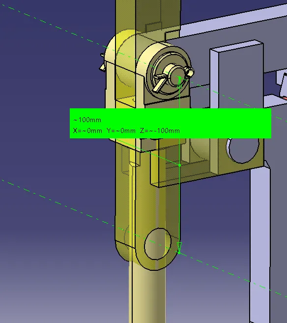
- Working Height - The type of welding fixture—robotic or manual—determines this. Working heights for manual fixtures range from 850 to 1100 mm, depending on the country's standards. We can all reach a height of 450 to 550 mm if the base structure is constructed with a base plate and tubular structure welded underneath it. In this instance, we must build more leg structure—possibly with the top and plate welded to the tube—in order to achieve the working welding height. This unit has a total working height of 1475mm. The base plate's measurements are determined to be 1700x980x30mm.
- For the fixture to be as small as feasible, the base unit needs to be sufficiently sturdy. The force of the welding clamping of the work piece is what causes this fixture deflection. The base plate machined to preserve parallelism, can readily support the weight of units without deflecting. The leg assembly and Weldment support portion is constructed from seamless pipe capable of withstanding the stresses generated by the clamping and welding of the workpiece.
- The base unit can be constructed from straightforward parts, allowing subsequent components to be welded or screwed together as needed. Welding is an option for the fixture's permanently attached parts. Screws may be used to secure items that need to be changed often. The base units permanent components are joined by welding, and additional components can be attached to the base unit. The threaded bolts can be used to secure all of the units and rough locators. The purpose of the base and plate is to assemble these units without causing failure to one another.
- Every unit inside its outer perimeter, including the entrance, should be covered by the base units.
- There should be a mechanism for altering the height of the base unit, which is parallel to the floor. The purpose of the height-adjusting device is to keep the floor level. In order to keep parallelism with the floor during adjustment, we can supply spacers.
3-2-1 PRINCIPLE
Fixing the work piece with a pin unit is our ultimate goal in order to prevent it from moving while the operation is being done on it. We apply the 3-2-1 principle as a result.
The Six degree of freedom that each component has are as follows,
- Translational motion along X-axis
- Rotational motion along X-axis
- Translational motion along Y-axis
- Rotational motion along Y-axis
- Translational motion along Z-axis
- Rotational motion along Z-axis
Simply put, degrees of freedom are the directions in which each component can move. If we also take into account rotation in an anticlockwise direction and translation along the negative, these six degrees become twelve. This implies that when a component is free, it can move in any direction. However, for obvious reasons, such free -to-move bodies cannot be subjected to procedures like welding, stamping, or anything else. Therefore, in order for a worker to work on the body, it must be restricted in all of its major directions. The 3-2-1 method is used to create this motion constraint.
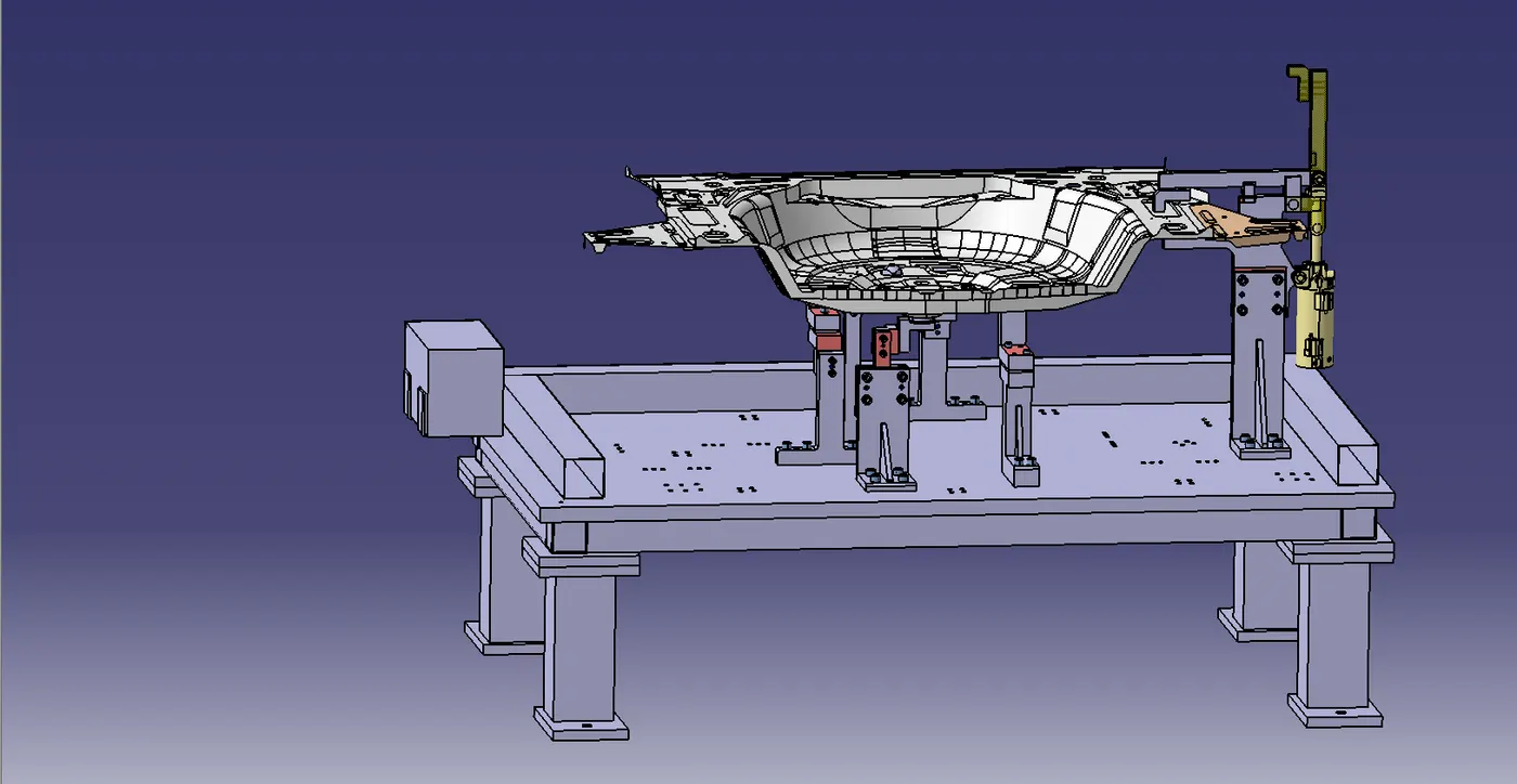
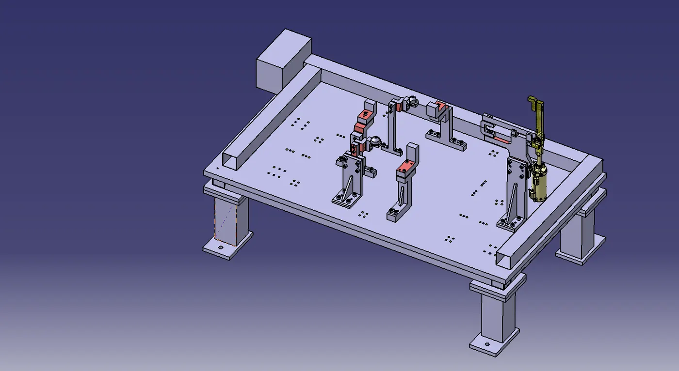
FINAL DESIGN
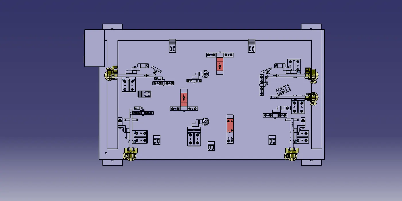
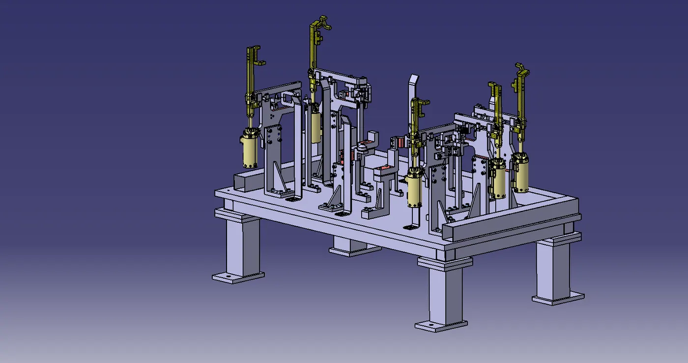
CONCLUSION
Therefore, utilizing the 3-2-1 concept, a base unit containing all of the welding for a certain vehicle panel and all of the other remaining units have been constructed for the given car panel and its movement has been fixed.