Week 7:- Base Unit Design Challenges 1
Week 7:- Base Unit Design Challenges 1
1) What is the Base Unit? What are the typical parts of the Base Unit?
a base unit is a unit with plate of holes or T slots that can be served as the mounting point for supports, locators and clamps.
In this method, there is not much attention to use standard parts for clamps, supports, and locators.
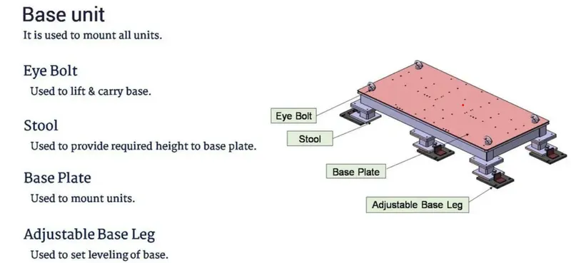
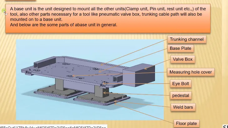
Typical parts of the base unit :-
I) Base Plate :-
Base Plate is a machined plate made of steel or Aluminium of thickness 25mm to 40mm on which the holes are drilled to
mount diffrent units like rest units, clamp units, pin units etc.
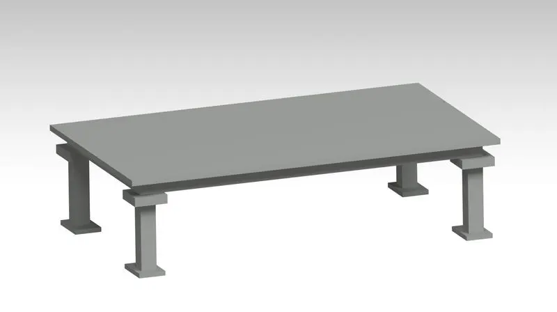
II) Trunking Channel :-
Cable trunking is an enclosure usually with a rectangular cross section, and with one removable or hinged side, that is used
to protect cables and provide space for other electrical equipment. They make electrical ducting and cable trunking
for concealing and securing cabling.
Trunking Channel is a duct that carries all the electrical and pneumatic connections(wires and pipes) for units of the tool.
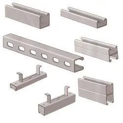
The standards of trunking sizes :-
50mm x 50mm
150mm x 75mm
75mm x 50mm
150mm x 100mm
75mm x 75mm
150mm x 150mm
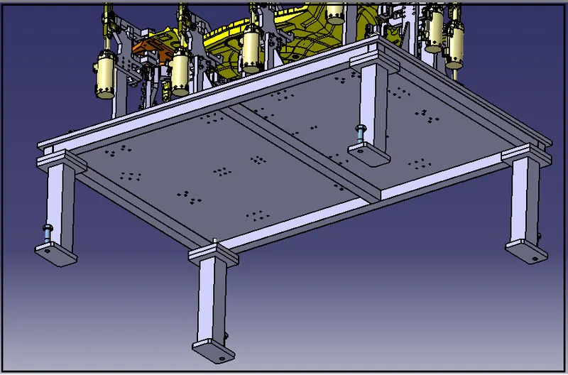
III) Pedestal :-
* It is used to connect the base plate with a floor plate.
* The pedestal can be a standard part or a make part, depending on the size and height of the fixture.
IV) Valve box
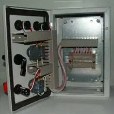
Pneumatic valves play an important role in a pneumatic system. They determine how much air passes through and in
which direction. This means that they can be used as control valves, but also as safety valves that shut off the air
supply in dangerous situations or that depressurise the system.
The valves pressurize and exhaust one outlet port to control a single-acting cylinder, or pilot another valve.
V) Measuring hole cover :-
The measuring hole is drilled over the base plate which having exact cordinates and acts as reference for the
other holes. Due to irregular shape of the car panel the holes coordinates are not
nominal like 250.0, 310.0 But it like 250.62,310.84. These holes are covered by using some plate to protect
against dust, damage etc.
VI) Eyebolt :-
Eye bolts used as a connection point for rigging, anchoring, pulling, pushing, or hoisting applications.
Although eye bolts are commonly used in BIW applications.
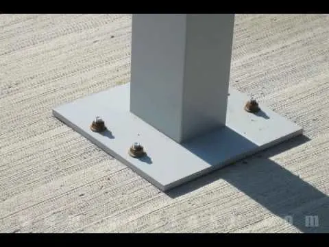
VI) Floor Plate :-
Floor plate is simple plate which holds the legs of BIW fixture to floor surface.
The base plate acts as an interface between the BIW fixture and the foundation, completing the load path into the floor.
Base plates help provide a uniform distribution of superstructure loads to the foundation
VII)Weld bar :-
A weld bar in a BIW fixture is a metal rod or bar that is used to hold the car body parts in place during the welding
process. The weld bar is usually attached to the fixture's base plate and is positioned to align with the joint
between two metal parts that need to be welded together
* Weld bars are used after the levelling is done by levelling screw.
*Weldbars are steel plates along the sides of the base plate of a pedestal.
*Weld bars are used to position the positions permanently.
2) What are the points need to account while designing a Base unit?
a) Part Compatibility: The fixture must be designed to hold the specific car body parts in the correct position, taking
into account the unique shape and size of each panel.
b) Welding and Assembly Processes: The fixture must be designed to accommodate the specific welding and
assembly processes required for each part, ensuring that the parts are securely held in place and positioned correctly
during the operation.
c) Accuracy and Repeatability: The fixture must be designed to maintain the required level of accuracy and
repeatability to ensure consistent results during each cycle of the assembly process.
d) Adjustability: The fixture must be adjustable to accommodate variations in the parts or to accommodate changes
in the assembly process over time.
e) Load-Bearing Capacity: The fixture must be able to withstand the weight of the parts and the forces generated
during the welding and assembly processes, while still maintaining its accuracy and repeatability.
f) Ease of Use: The fixture must be designed to be easy to use and maintain, with clear and simple instructions for
making adjustments or repairs as needed.
g) Cost Effectiveness: The fixture must be designed to be cost-effective, taking into account the cost of materials,
labor, and any additional equipment needed to produce the fixture.
h) Durability: The fixture must be designed to withstand the harsh production environment and repeated use,
and be able to last for a long time without requiring frequent repairs or replacement.
3) What is a Dump unit?
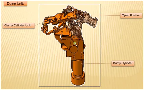
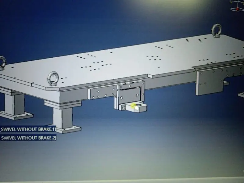
A dump unit in a BIW fixture is a mechanism used to adjust the angle or orientation of the fixture. The dump unit allows
the fixture to be tilted or rotated, enabling access to different parts of the car body for welding or assembly.
The dump unit is typically mounted on the base plate of the fixture, and it typically consists of a hydraulic or mechanical
actuator that is used to adjust the angle of the fixture. The actuator can be controlled manually or by a computer
controlled system, depending on the needs of the manufacturing process.
The dump unit is an important component of a BIW fixture, as it allows for flexibility and ease of use in the
assembly process. It enables the operator to access difficult-to-reach parts of the car body, reducing the risk
of injury or strain, and improving the overall efficiency of the assembly process.
Overall, the dump unit is a key feature of a BIW fixture that helps to increase the speed, efficiency, and quality
of the car body assembly process.
4) What are the points you need to consider while designing a Dump unit?
a) The dump unit must be designed to support the weight of the car body parts and the BIW fixture, and to withstand the
forces generated during the welding and assembly processes.
b) The dump unit must be designed to maintain the required level of accuracy and repeatability to ensure consistent
results during each cycle of the assembly process.
c) The dump unit must be designed to be easy to use and adjust, with clear and simple instructions for making
adjustments or repairs as needed.
d) The dump unit must be designed to be safe for the operator to use, with safety features to prevent accidental
movement or release of the car body parts during the assembly process.
e) The dump unit must be designed to withstand the harsh production environment and repeated use, and be able to
last for a long time without requiring frequent repairs or replacement.
f) The dump unit must be designed to be cost-effective, taking into account the cost of materials, labor, and any
additional equipment needed to produce the fixture.
g) The dump unit must be designed to integrate seamlessly with the rest of the BIW fixture, allowing for smooth and
efficient operation during the assembly process.
5) What is a Slide unit?
A slide unit in a BIW fixture is a mechanism used to adjust the position of the fixture along a horizontal axis.
The slide unit allows the fixture to be moved along the horizontal axis, enabling access to different parts of the car body
for welding or assembly.
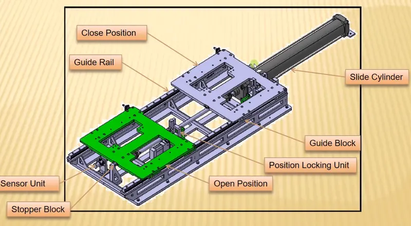
The slide unit is typically mounted on the base plate of the fixture, and it typically consists of a linear actuator, such as a
hydraulic or pneumatic cylinder, that is used to adjust the position of the fixture along the horizontal axis. The actuator
can be controlled manually or by a computer-controlled system, depending on the needs of the manufacturing process.
Overall, the slide unit is a key feature of a BIW fixture that helps to increase the speed, efficiency, and quality of the
car body assembly process.
6) What are the points you need to consider while designing a Slide unit?
a) The slide unit must be designed to support the weight of the car body parts and the BIW fixture, and to
withstand the forces generated during the welding and assembly processes.
b) The slide unit must be designed to maintain the required level of accuracy and repeatability to ensure consistent results during each cycle of the assembly process.
c) The slide unit must be designed to provide smooth and controlled movement along the horizontal axis,
with minimal vibration or disturbance to the car body parts during the assembly process.
d) The slide unit must be designed to be safe for the operator to use, with safety features to prevent accidental
movement or release of the car body parts during the assembly process.
e) The slide unit must be designed to withstand the harsh production environment and repeated use, and be able to last
for a long time without requiring frequent repairs or replacement.
f) Integration with the Fixture: The slide unit must be designed to integrate seamlessly with the rest of the
BIW fixture, allowing for smooth and efficient operation during the assembly process.