Week 7:- Base Unit Design Challenges 1
Week 7 - Base Unit Design
1: What is the Base Unit? What are the typical parts of the Base Unit?
Base Unit:
The base unit is the unit of the fixture which is designed as such so that other units of the fixture can be mounted on it. Apart from these units, other necessary tools like a pneumatic valve box and trunking cable path will also be mounted on the base unit.
The base unit is the fundamental component of the fixture because all other components are mounted over it.so every fixture has a base unit. The base unit design is different according to the panel, Design of clamp system, location system, etc.
Parts of the Base Unit:
- Base plate Pedestal
- Trunking channel
- Valve box
- Eyebolt
- Floor plate
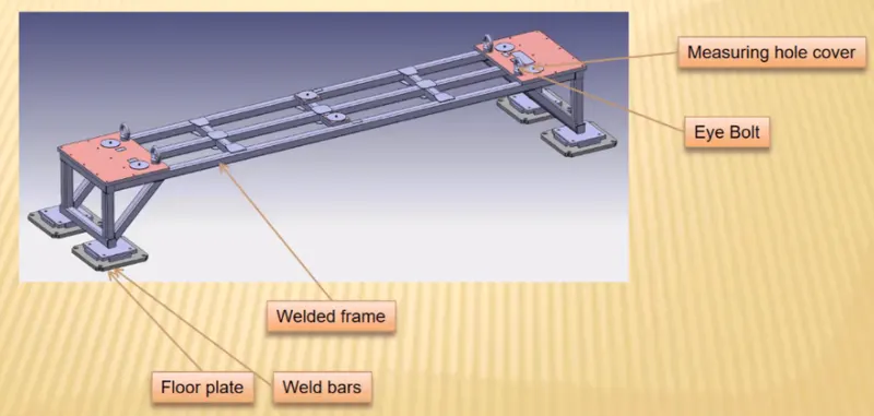
Welded Base Unit:
1. BASE PLATE:
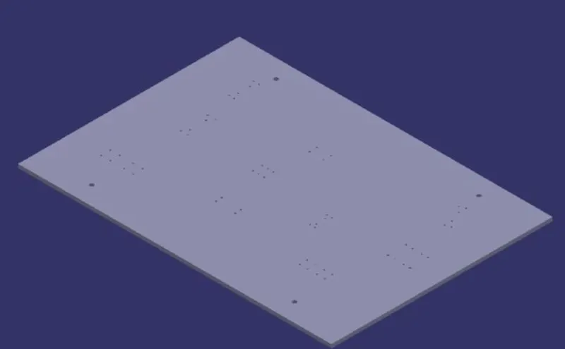
A base plate is a machined plate of 25 to 40mm thickness made of steel and aluminum on which the holes are drilled to mount individual units like clamp unit, pin unit, rest unit, etc.
2. PEDESTAL:
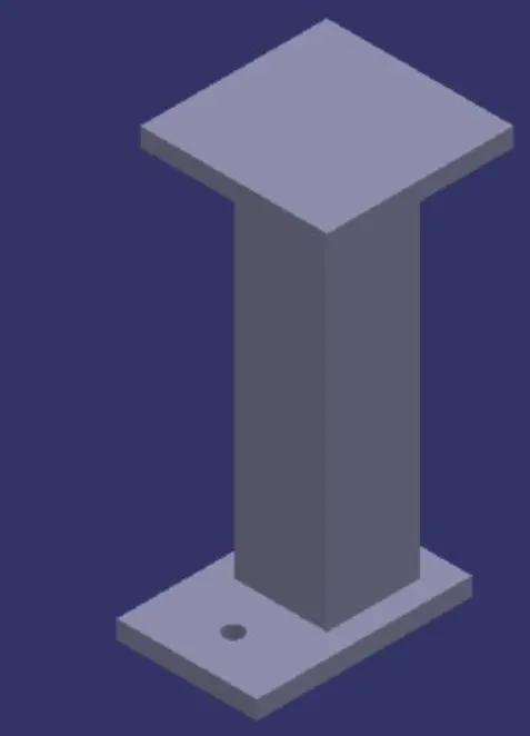
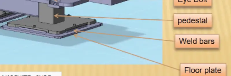
A pedestal is a part that connects the base plate to the floor plate. A pedestal is a standard part in general and in some cases, it can be a welded frame integrated with the base plate.
- A standard pedestal can be of different heights and different sizes.
- Depending on the size of the base plate, the number of pedestals varies for load distribution.
- Pedestals are of different types with different inclinations.
3. Trunking Channel:
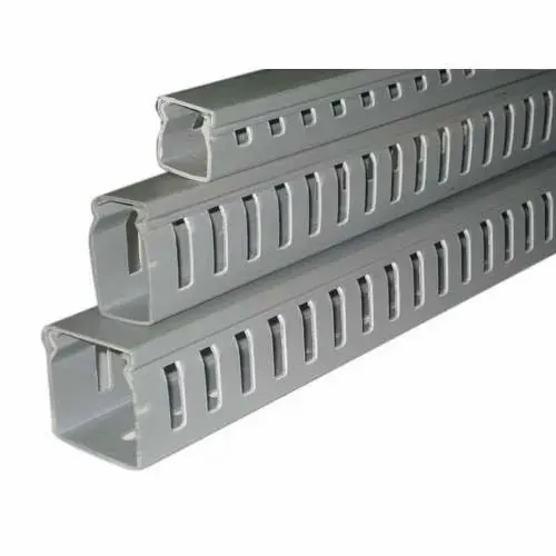
Trunking Channel is a duct that carries all the electrical and pneumatic connections(wires and pipes) for units of the tool. It has a thickness of a few millimeters.
4. Valve Box:
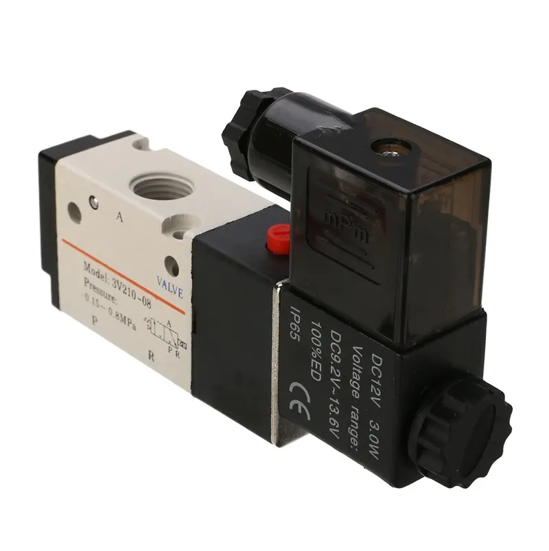
The valve Box is a standard part that contains all the valves for the pneumatic units. The valve box is the box that includes different solenoid valves. The pneumatic fixtures work on air pressure provided to it. So the arrangement of air pressure inlet & outlet is done within this valve box.
The trunking channel includes all the pressure inlet cables going to the pneumatic parts of the fixture & protects them from damage while the operation is in process.
5. Eye Bolts:
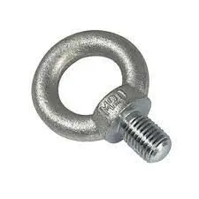
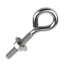
Eye bolts are used for the transporting of the tool, using lift hooks, forklift holes will also be provided in some cases for transporting purposes. For example, we usually use M20 bolts that are bolted on the base plate.
When installing lifting eye bolts it is critical to ensure the face is in firm contact with the mating surface. These lifting rings are intended for linear pulling loads in the direction of the thread.
They are not intended for use where the load is perpendicular to the thread. This is because in these instances the bolt could unscrew and move or it could be twisted and break
6. Floor Plate:
The floor plate is grouted to the floor with a fixed bolt on the ground. Floor plates are also called foundation plates.
- There will be a clearance of 10 mm maintained between the pedestal base plate & floor plate.
- This clearance will be used by the leveling screws, for leveling the entire tool.
- Weld bars are used to weld the positions permanently after leveling is done.
- A weld bar is a plate along the sides of the base plate of the pedestal.
2: What are the points need to account for while designing a Base Unit?
1. Working Height:
- It depends on the nature of the manual or robotic welding fixture.
- For manual fixtures working height of 850-1100 mm is needed to be considered, depending upon the working height of the worker standard of a specific country will apply (In a few countries human height is higher or lower e.g. US, Japan).
- If the base structure is made with a base plate having a tubular structure welded below it then we can reach to height of 100 mm to ~250 mm. In this case to reach the working welding height we need to provide additional some leg structure which may have the top and plate welded to the tube.
- Try to study the gun ergonomics properly then design the unit height and then base top height.
2. Base Plate or Welded Structure:
- Depending upon the component size and weight of the total units we can decide whether we need a fabricated base or just a plate.
- Mostly fabricated bases are used made of square or rectangular tubes with plates.
3. Selection of Eye Bolt:
- As a designer, it is important to know how a big base plate or bigger base welded structure will be handled during the fabrication and handling process.
- Depending upon the weight eye bolt size is selected for lifting holes on the base plate.
- Generally, 4 eye bolt provision is made. We also need to select the location of the eye bolt considering the rope/ belts used while shifting the structure or complete fixture are not damaging any units (rest, clamp, or location units) nearby.
4. Number of Measuring Holes Required:
- We would need 3 holes to define the plane.
- Most of the OEMs makes 4 dowel holes at 4 corners and put small aluminum plate marking the X, Y &Z coordinates of dowel holes.
- If the base length is too long few OEMs follow the methodology of having dowel holes at a 500mm distance.
5. Base Plate:
- There are few OEMs, Line builders use only thick base plates. Few OEMs recommend a thick base plate of 40mm or 50mm for the child part assemblies (e.g BMW). 40/50mm plate makes a very heavy structure but some OEMs follow the methodology.
- If we go for a higher thickness it will not bend after machining and will have good flatness.
- The general observation is if we go for a 10-12 mm thick plate for a large size e.g. 2mx2m, after machining when we unclamp the plate from the milling machine the plate will not show good flatness.
Fundamentals of base plate design:
- A base plate size should cover all the units with its outer periphery including the opening.
- A base plate is preferred to be designed concerning BCS coordinates.
- A base plate should be drilled with datum holes/ measuring holes in line with a pitch of 100mm in general.
- The number of datum holes depends on the size of the base plate.
- Datum holes should be drilled at nominal values of coordinates and in terms of 50 and 100.
- Datum holes should be drilled with a diameter 100mm away from other units.
- Datum holes should be covered with cover plates.
3: What is a Dump Unit?
Dump Unit:
The dump unit is used when we have any constraints and we cannot use our normal units like clamp unit and pin unit etc. In such cases, to fix them, we use a dump unit. A dump unit can have more than one cylinder to perform such an operation. The first cylinder dumps the assembly carrying clamp mylars, and pins, and then this assembly performs the required operation. In this unit, we should make sure that in the open position of the panel, we should be able to remove the panel.
A dump unit can have a slide cylinder or a clamp cylinder attached to it. Cylinder validation is important in the case of a dump unit as the weight can be too heavy for the cylinder to dump. In such a case, calculations are done and the force exerted by the cylinder is checked against the weight of the load being carried. If cylinder force is more, it is validated or we use a more powerful cylinder.
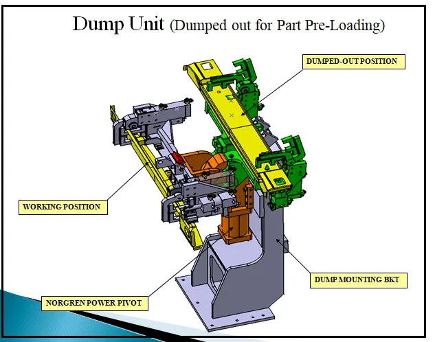
Functions of the dump unit:
- To ensure proper resting of the panel being welded and to restrict its motion.
- To ensure there is no rotation in the panel and to fix it either by pins or side blocks or magnets.
- To ensure there is enough clamping force in the cylinder so that it doesn't move while welding.
- The dump unit should have correct shimming for adjustment of the panel.
4: What are the points you need to consider while designing a Dump unit?
As a dump unit is complex to design because of a lot of parts, we have to be considerate while designing it as any errors during the designing stage creates a lot of problems at the later stage which would result in loss of time and money and eventually more time and money to rectify the problems. Following are the points we need to consider while designing a dump unit:
1. 3-2-1 Principle: Like every other fixture unit, this unit too has the function to restrict the motion of the panel which is being worked upon that is being welded. Other units like the clamp unit will be mounted on this unit to hold to a panel at the place. Thus it is logical and important for the dump unit to follow this principle.
2. The dump unit must be placed on the fixture such that it does not block or collide with other units of the fixture and it must not collide with the weld gun.
3. Same goes with the open position of the dump unit. It takes more space than the rest of the units as in other units like clamp units, only the clamp arm open and closes but for the dump unit, the open position is the opening of the clamp cylinder with its other parts. Hence we must take care that wherever we place the dump units, we must have a lot of space.
4. Cylinder Validation: It is the process of analyzing the cylinder used by doing some measurements and calculations to know if the cylinder used is proper. In-cylinder validation process we determine the force required to open and close the moving part of the unit. If the force obtained is within the limits of the force specified on the cylinder then we can use this cylinder else we have to change the cylinder.
5: What is a Slide unit?
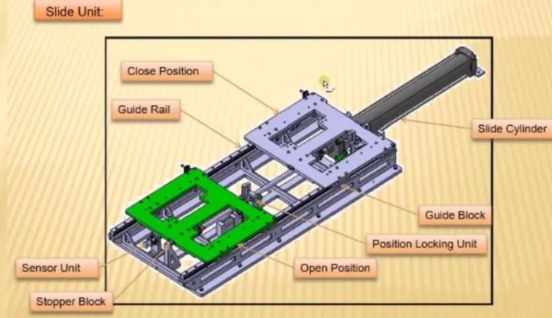
Similar to the dump unit, a sliding unit is also used where we have space constraints. It consists guide block, guide rails, sensor unit, stopper block, position locking unit, and slide cylinder.
1. Slide cylinder: This helps in the actuation of the platform from the closed position to open position and vice versa.
2. Sensor unit: This unit senses if the panel is at its position or not.
3. Guide rails: This helps in the movement of the platform between open and closed positions.
4. Position locking unit: It locks the open or closed position.
5. Stopper: It restricts further motion when in the open position.
Classification of Slide Unit:
Based on the type of guide ways:
- LM guide way
- Hardened guide way
Based on the prime mover used
- Manual slides
- Hydraulic/Pneumatic slides
- CNC slides
Based on application
- Horizontal slide
- Vertical slide
- Angular slide
6: What are the points you need to consider while designing a Slide unit?
The following points must be kept in mind while designing a slide unit:
1. Weight Carrying Capacity
There are different kinds of guide rails available in the market, each having a different load capacity. Hence, we calculate the weight of our assembly and calculate the weight capacity of the rail. Hence, we choose rail based on its load-carrying capacity.
2. Push and Pull Forces
We need to check the push and pull forces and check if it is enough to push and pull the slide especially when the slide is at an inclination.
3. Locking Mechanism
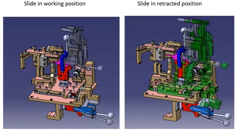
The locking mechanism ensures that the slide does not move while it is open or retracted position. If the slide moves while welding, it can damage the panel as the positional accuracy will be hampered.
4. Stopper Blocks
Stopper blocks are used to stop the slide at the required position. It is important as if the slide unit has rest mylars and pins, they need to be stopped at their respective position for proper resting and location. Without a stopper, it may dent the panel.
5. Sensor Unit
The sensor unit helps to check the position of the slide. When the operation is going to start, the operator pushes the button and the slide moves forward, the sensor gives this signal of the presence of the unit to the PLC which then performs the next operation.
6 Stroke
We need to select the length of stroke based on the work area we want to get cleared. Reserve stroke of 10mm to be considered in both forward and retracted conditions. Cylinder and LM guides must be validated for load and stroke. LM guide rail length must be standard and more than the actual stroke
7 Open position
The only moving parts are that one the slides, so we need to check the fowling with a gun or other unit nearby. Only after this has been checked that we can approve the design.