Photo Realistic Rendering
Designing of American Chopper using Solidworks
Objective:
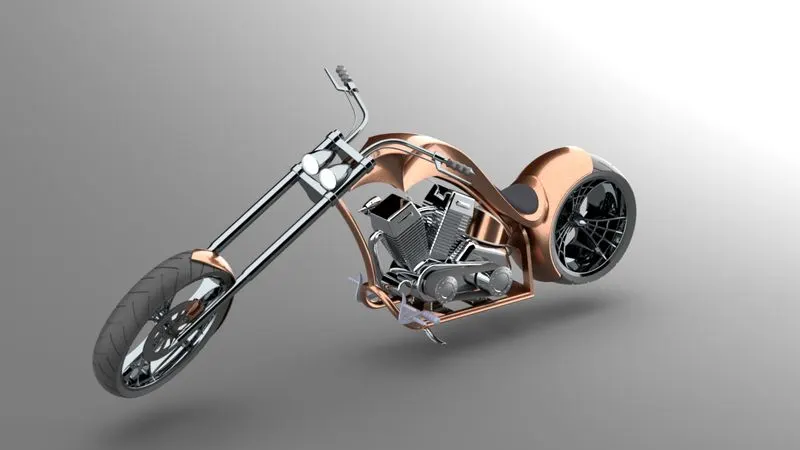
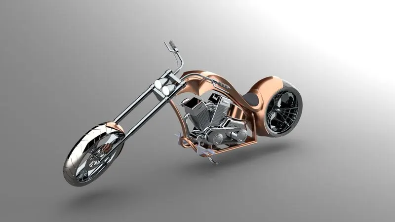
The objective of this project is to design and render a photorealistic cosmetic model of an American chopper using Solidworks and Solidworks Visualize.
Introduction:
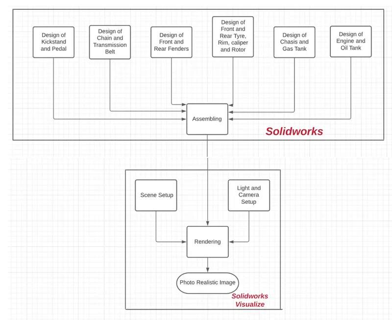
This is a conceptual design of American chopper where the parts like front and rear tires, front and rear rim, fenders, fork, gas tank, engine, chain, calipers, sprocket, and transmission belt are designed to approximate actual dimensions. The internal parts and features are not considered for designing since the design is just for cosmetic models. Then these parts are assembled with the required constraints. Next to assembling, the assembled model is imported into Solidworks Visualize to create the photorealistic rendering of the model by applying required environments, lights, and cameras. Then the rendered image is obtained. On the whole, the use of splines and project curves plays a huge role in creating complex geometries.
Design Methodology:
The methodology here is a top-down approach, where the parts are first created followed by assembly of these parts with required constraints.
Steps to be followed before modeling:
- Open Solidworks, Click on New, Select part, and choose the Document unit in my case I choose MMGS.
1. Transmission Belt
- Click on the plane which you need to sketch for me, I choose my front plane.
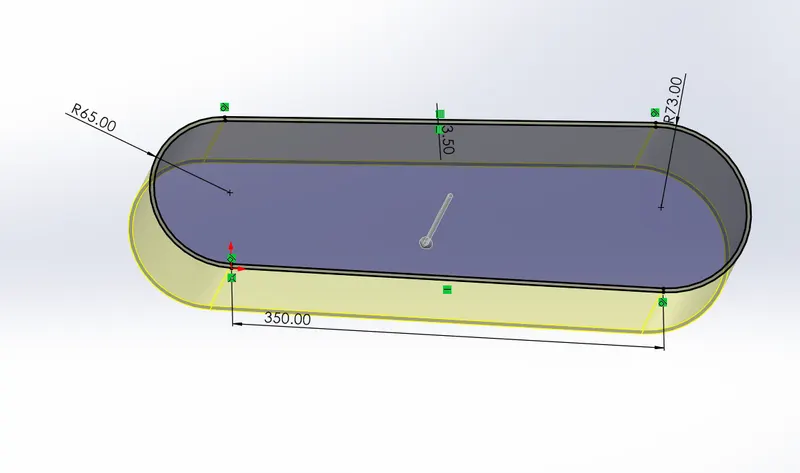
- Then sketch on the plane selected with the below diagram using circles, line tools and apply the necessary dimensions and constraints.
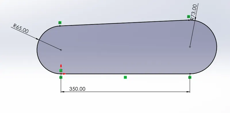
- Use offset entities tool to offset at a distance of 3.5mm, then click on exit sketch.
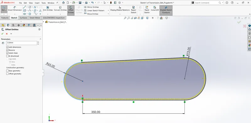
- Now, Select the Features tab and click on Boss Extrude
- On selected contours, select the sketch and enter the distance of 88mm for the extrude and click on ok
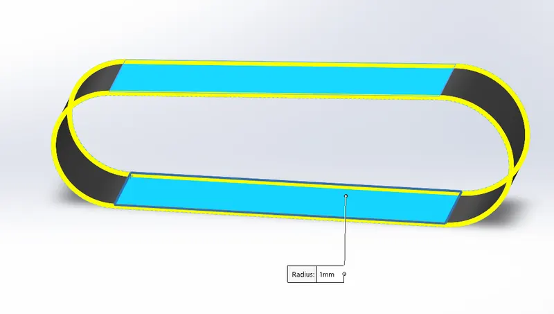
- Then apply Fillet to the outer edges of the belt with a radius of 1mm.
- Now save the document in the desired location.
- The design of the Transmission belt has been completed.
2. Front Fender
- Select the Front plane and get into the sketcher
- Sketch the profile you want to revolve as shown below using circle, offset, trim and apply the dimensions and constraints.
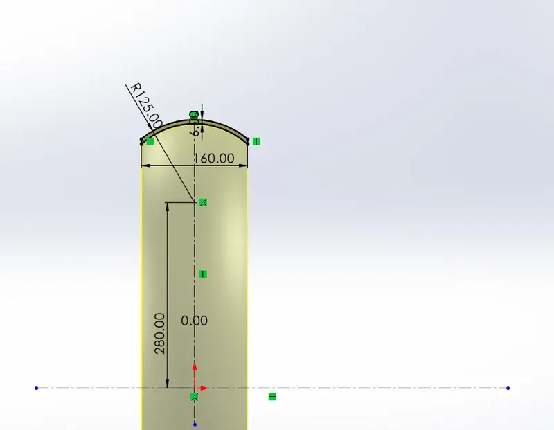
- Click on Exit sketch, from the features tab select Revolved Boss/Base option, Select the axis of revolution you want to revolve.
- From selected contours, select the sketch profile to revolve.
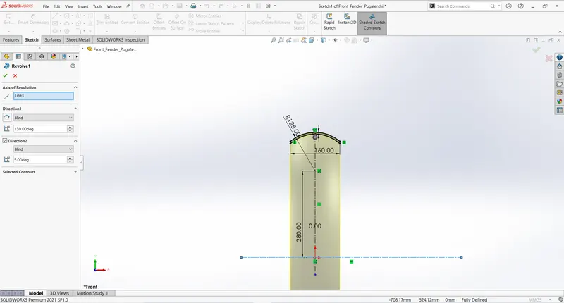
- In direction1, Enter the angle of 130deg and in direction 2, enter the angle value of 5deg
- Click on, the revolved profile is obtained.
- Select the top plane and sketch the profile shown using a 3point spline and apply dimensions and constraints.
- Use the dynamic mirror entities option so that whatever is made on one side is mirrored vertically.
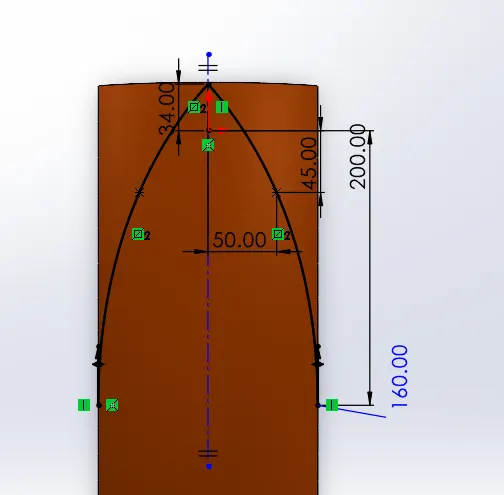
- Use the Split option, Select the profile drawn in trim tools and click on the cut part.
- Select the bodies to be removed from the part and click on consume bodies to delete it.
- Select the right plane and sketch the profile shown using 3 point spline, Dynamic mirror entities and apply dimensions and constraints.
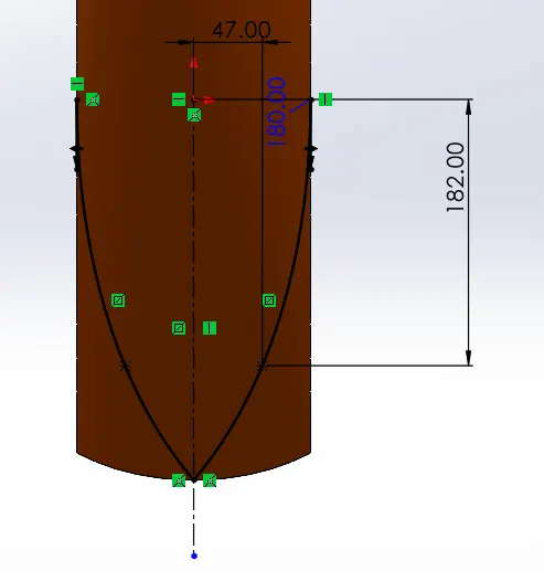
- Use the split tool to remove some bodies using the split line, click on the cut part, select the bodies to remove, and click on consume bodies.
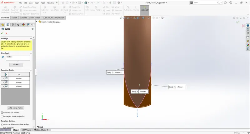
- Add fillets to the outer face with a radius of 6mm.
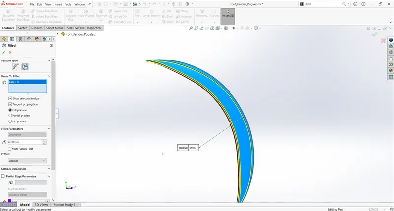
- Now save the document, the design of the front fender is completed.
3. Rear Fender:
- The modeling of the rear fender is similar to the modeling of the front fender, a profile is revolved around an axis with the angle in direction1 being 10deg and direction 2 being 140deg.
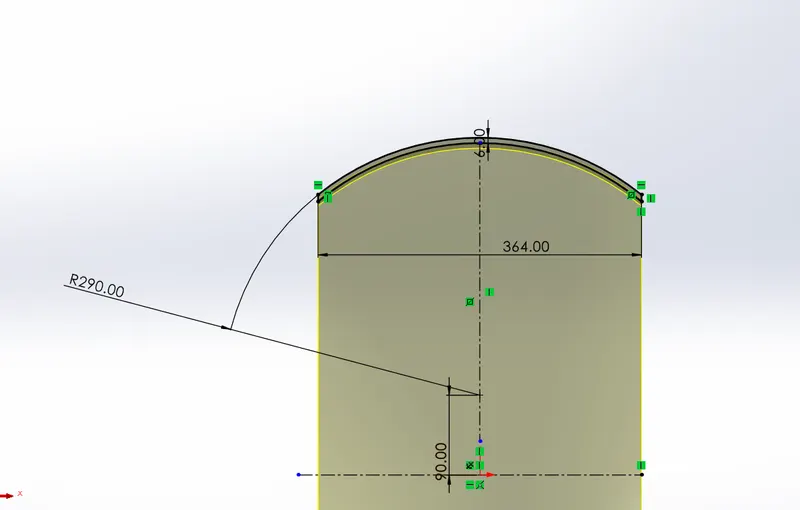
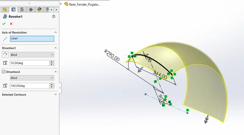
- On the top plane, a sketch is drawn with reference to this split tool is used to cut and remove bodies.
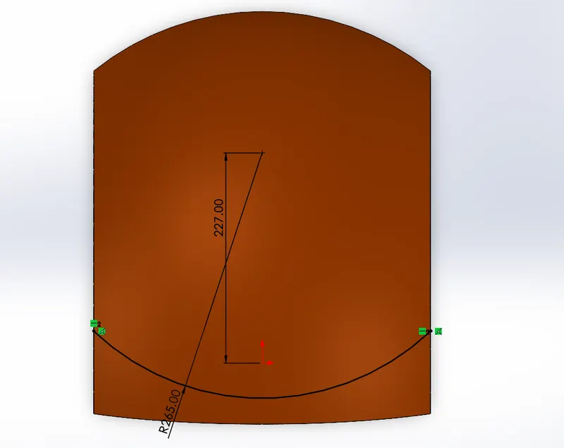
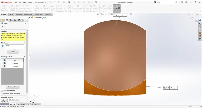
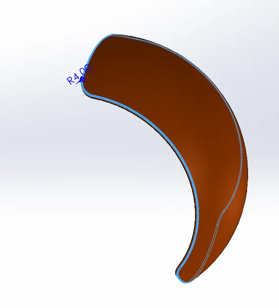
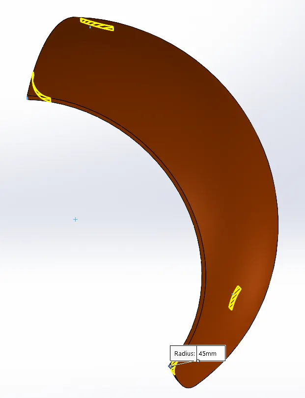
- Add a fillet to the four corners radius of 45mm and outer face of 4mm.
4. kickStand:
- Kickstand was modeled using a lofted boss where two ellipses are lofted with help of a guide curve.
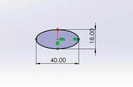
- Take the Front plane and sketch an ellipse at the origin.
- Now on the right plane draw spline from the origin, this spline is going to be the centerline for the lofted boss
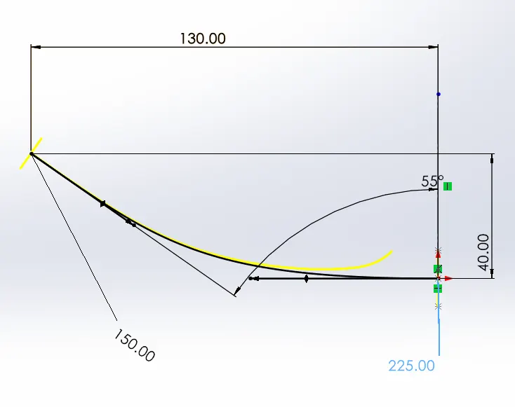
- Add a plane with references as spline and spine endpoint.
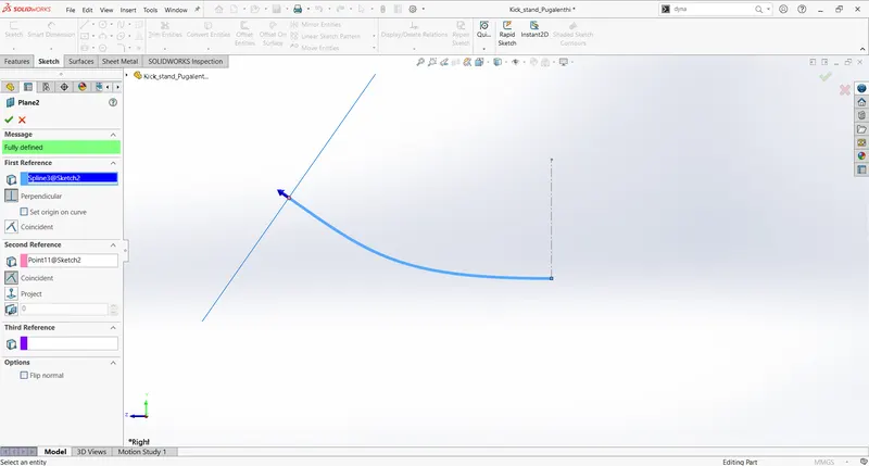
- Considering this plane, draw an ellipse
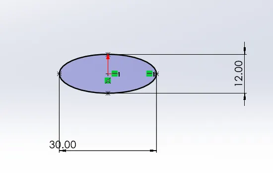
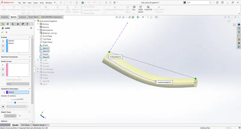
- Now it's the time to get the lofted boss, From the features tab, select lofted boss.
- In the profiles section, Select the ellipse profiles and in the centerline parameter, select the spline connecting ellipses.
- Make sure green dots are in a straight line
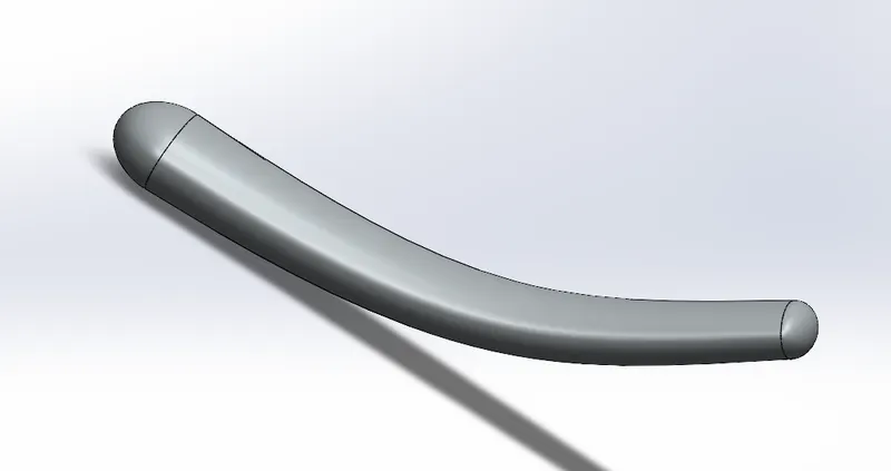
- Add dome to the two faces. Larger face with a dome of 13mm and a smaller one with 5mm.
- Make sure the elliptical dome is enabled.
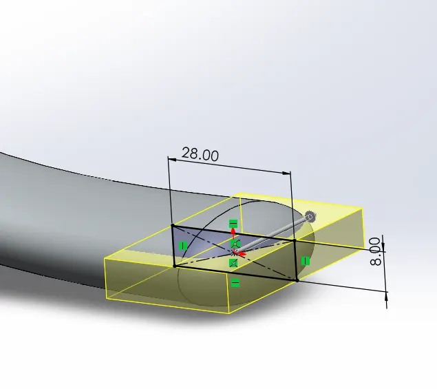
- On the Right plane, draw a rectangle from the origin and use a cut extrude tool to remove material for creating a boss for connecting kickstand with chassis.
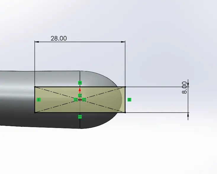
- Select the sketch in selected contours
- Use the Midplane option in the cut extrude tool to the distance of 48mm
- Create a circular boss at the origin of diameter 9mm by selecting the face and extruding up to the opposite face.
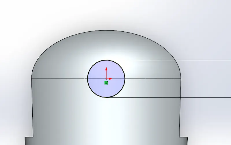
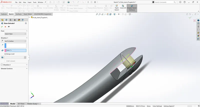
- Add a fillet to the inner edges
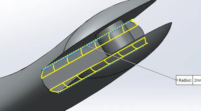
- And fillet of 0.5mm to the outer edges
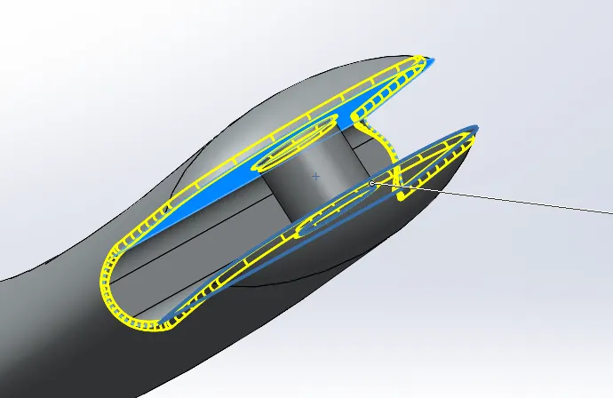
- To have a flat bottom with the ground, a split tool is used.
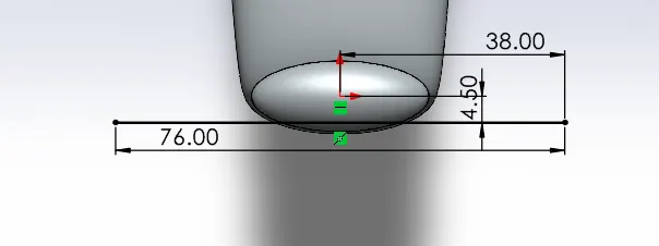
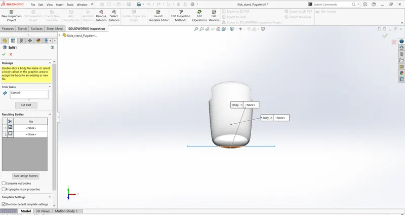
- Now save the document, the modeling of the kickstand is completed.
5. Pedal
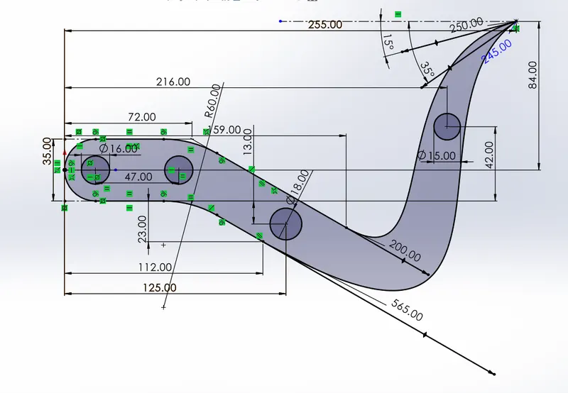
- The modeling of the pedal starts with the sketching of the profile in the front plane. The sketch is done using circles, lines, splines and adding necessary dimensions and constraints to the sketch.
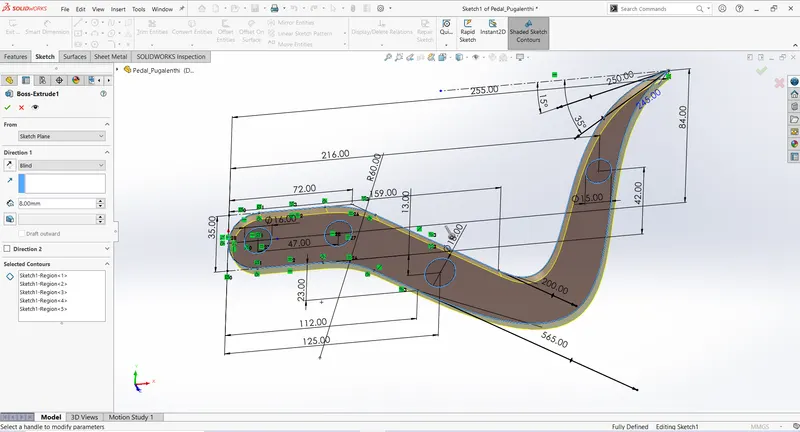
- By using boss extrude, the entire profile with circle regions is used for this extrude to the width of 8mm.
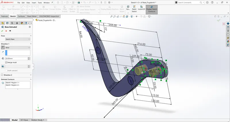
- Using the same sketch, the circles are shown are extruded in the opposite direction for the distance of 20mm.
- The circle region can be selected from selected contours.
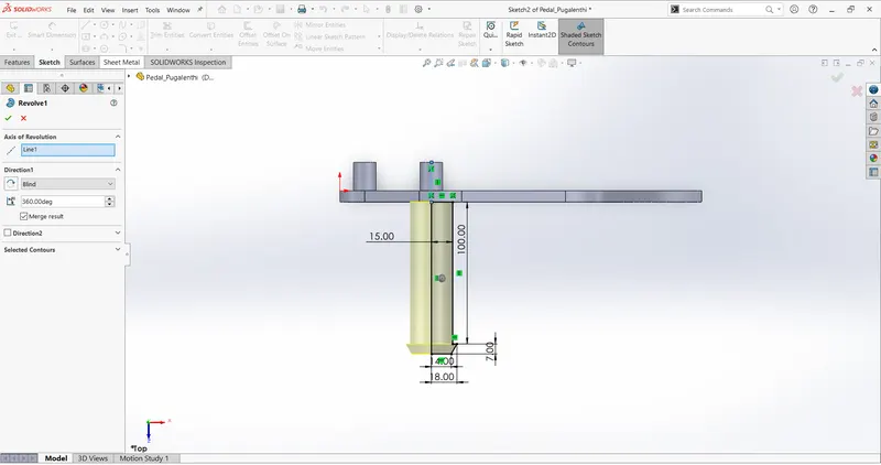
- Select the top plane for sketching, and sketch the profile to revolve. The profile is shown below.
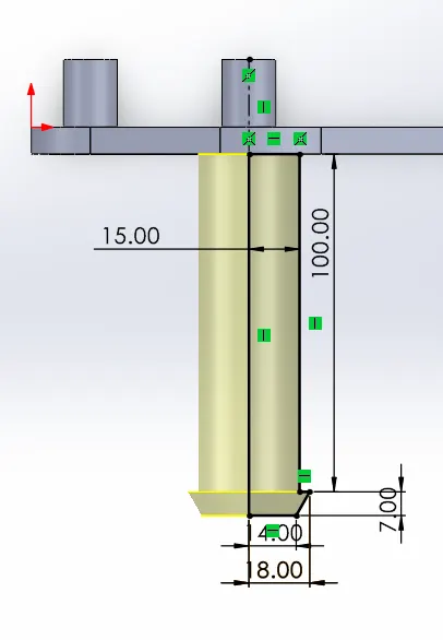
- Choose to revolve boss from the features tab and choose the line of revolution and degree as 360deg to get revolved model.
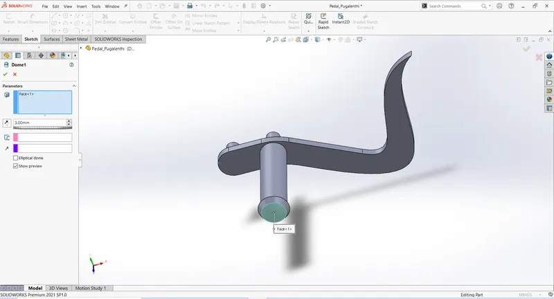
- Add dome feature to the end of the face of 3mm with elliptical dome option disabled.
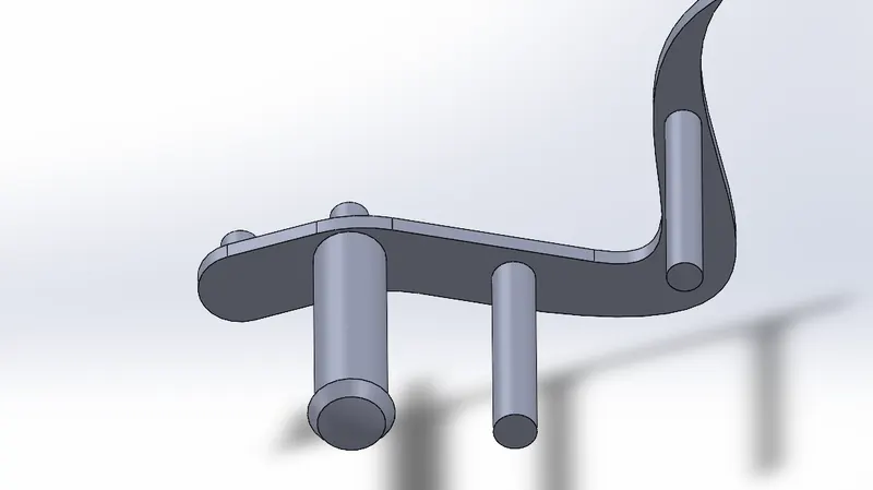
- From the first sketch use the remaining circles to extrude to the length of 100mm
- Add chamfer to the edge shown with chamfer type - asymmetric distance, distance, and value of 16,9mm
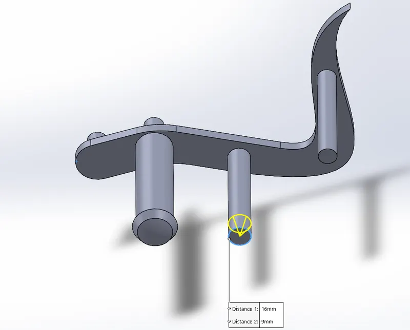
- Repeat the same for another cylinder with the same options and values are 16,7.5mm
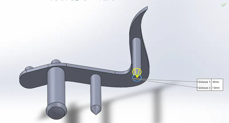
- Create a sketch on the face of the pedal as shown with the following dimensions.
- The sketch can be created using convert entities of extruded cylinders and offsetting them with their respective dimensions.
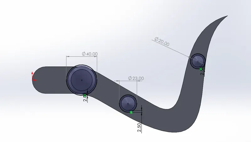
- The sketch is then extruded with an offset of 20mm from the face and a width of 2.5mm in direction1.
- The fillet radius of 1mm is added to all the edges of the geometry.
- Then the extruded ring is patterned linearly with four instances and a distance between the instances as 20mm and direction can be selected from any edge that shows the direction.
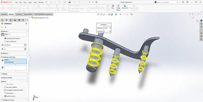
- Then save the document, the modeling of the pedal has been completed.
6. Front Wheel:
- Front-wheel is a multibody model with rim, rotor, caliper, and tire.
- The outer profile of the rim is revolved around the horizontal axis for the full rotation of 360 deg.
- The sketch is shown below
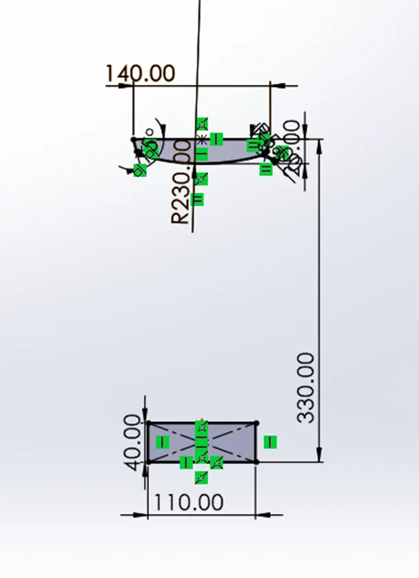
- Then, the rib of the rim is modeled in the following steps.
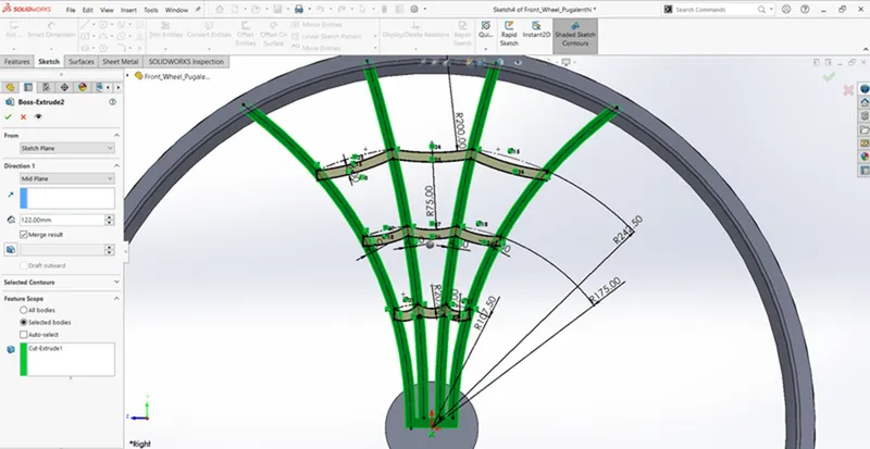
- On the Right plane, the profile is extruded for the width of 122mm using the midplane option.
- And the merge result option is disabled.
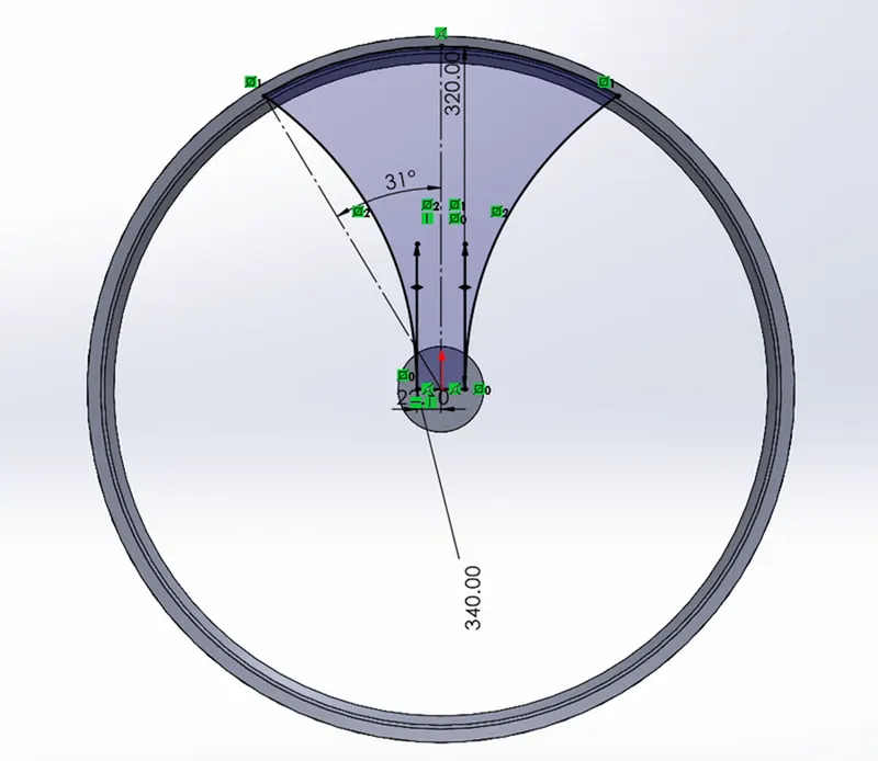
- Then, Profile can be obtained using splines, offsets, and lines as shown below.
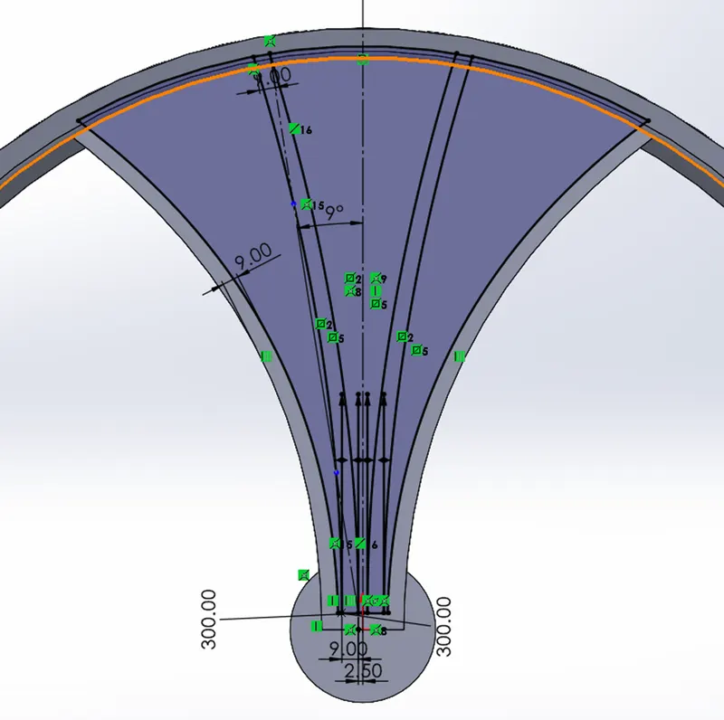
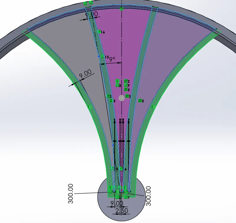
- The shown profiles are selected to remove material.
- To get the spider web design the following sketch was done.
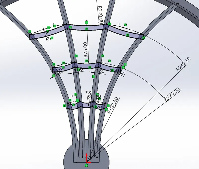
- The profile can be sketched using 3 point arcs and reference circles, the offset to 8mm, and extrude them using midplane for a distance of 122mm. Enable merge result and choose selected bodies in feature scope and select as shown below to get a combined internal rib.
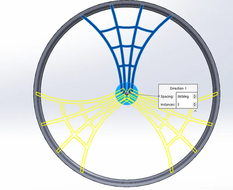
- Then this spider design is patterned circularly with equal spacing in 3 instances.
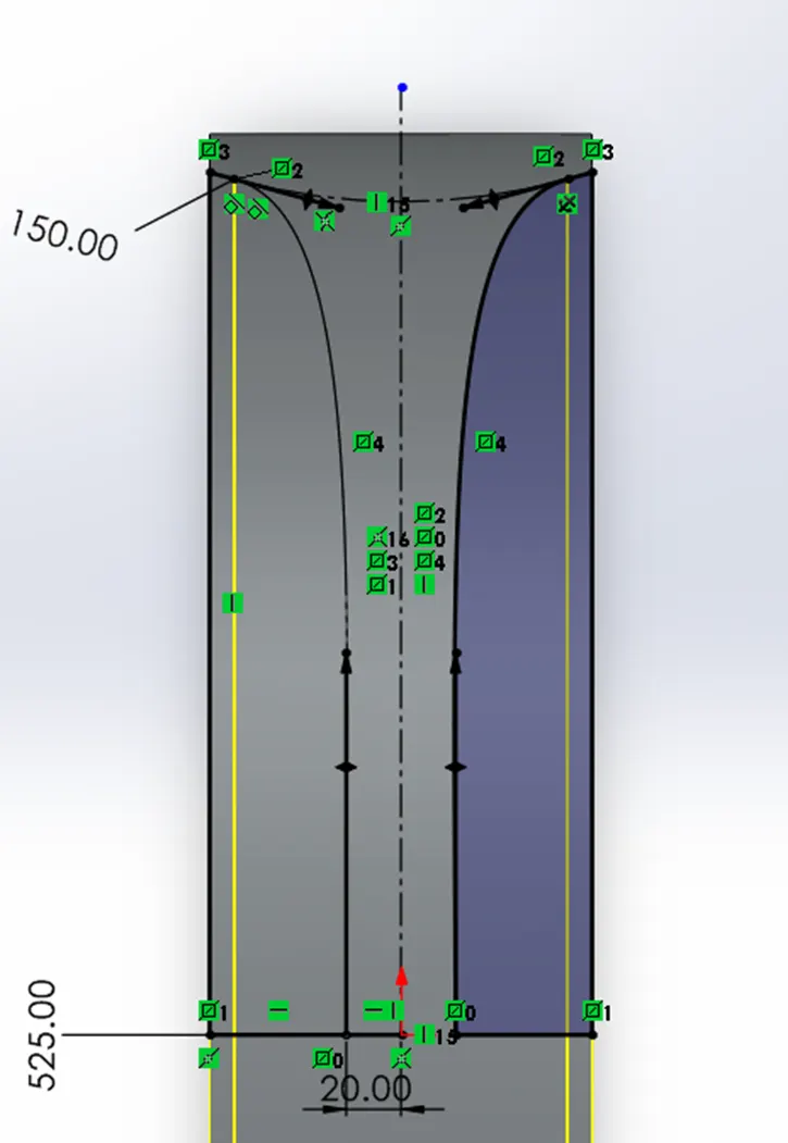
- Now to get the smooth internal profile, the below sketch is used to remove material.
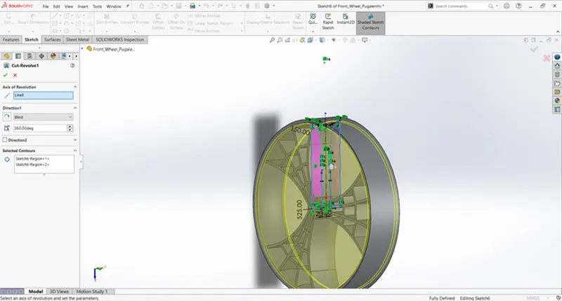
- The sketch is drawn using lines, splines, and centered vertical construction lines with dynamic mirror entities enabled.
- Now, this sketch is used in the revolved cut along the horizontal axis.
- Apply a fillet of 4mm to all the internal edges of spider web ribs.
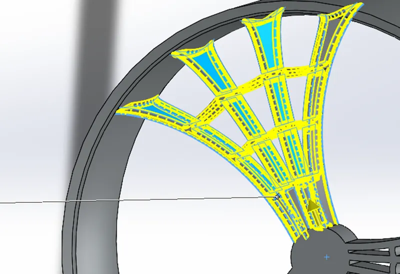
- To get the disc rotor, sketch a circle of 345mm diameter on the right plane.
- Extrude the circle with an offset of 45mm from the plane and a width of 7mm. The merge result option is disabled as this is a separate body.
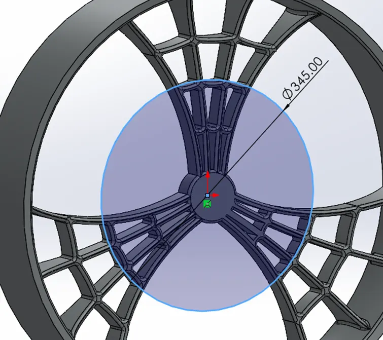
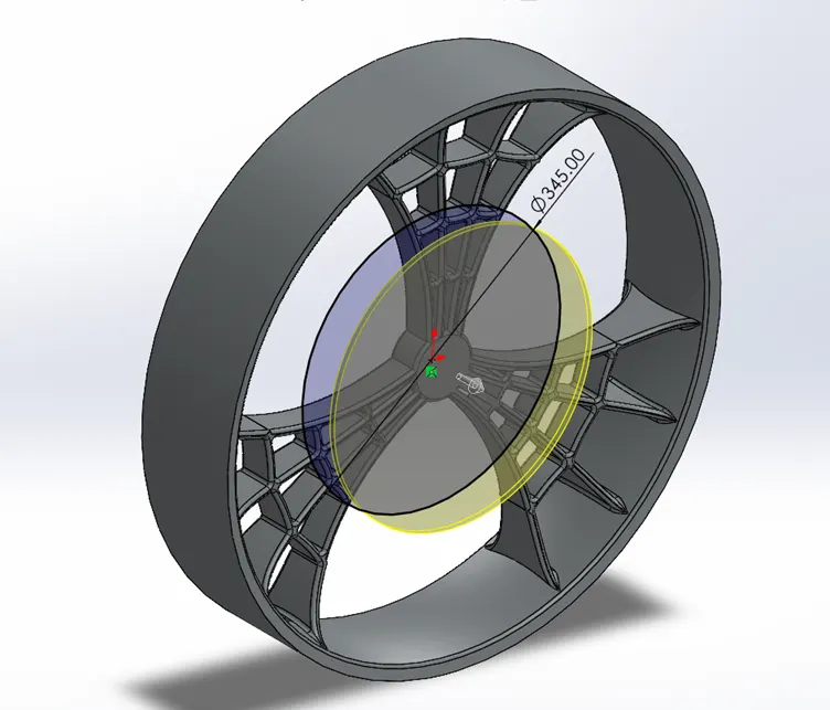
- To get the holes as in the disc rotor, the holes are created and patterned circularly. The no of instances is 14.
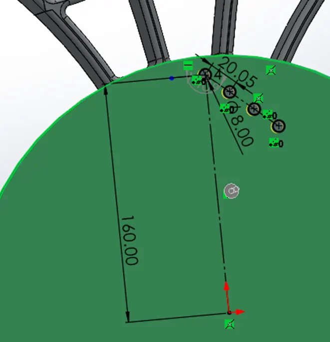
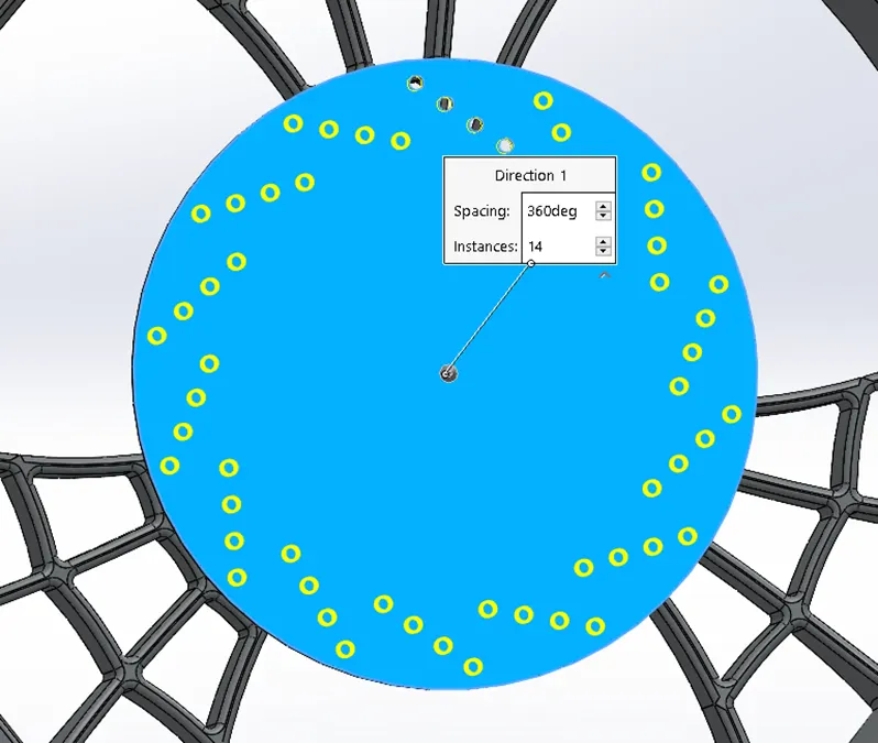
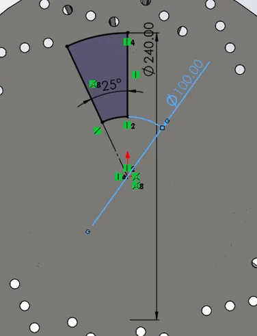
- Fillet of 5mm is added to the internal edges.
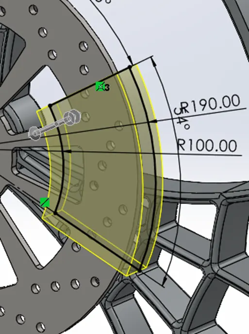
- The above profile is sketched on the face of the disc rotor. Then this sketch is used in cut extrude to remove material. And patterned circularly with 10 instances equally spaced.
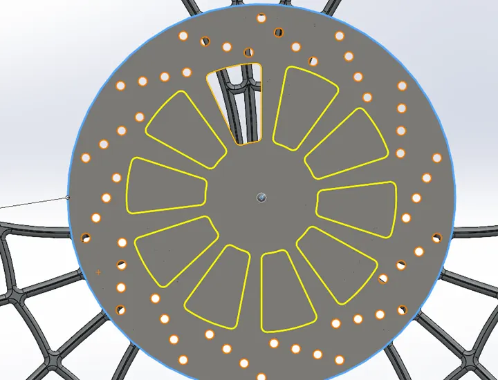
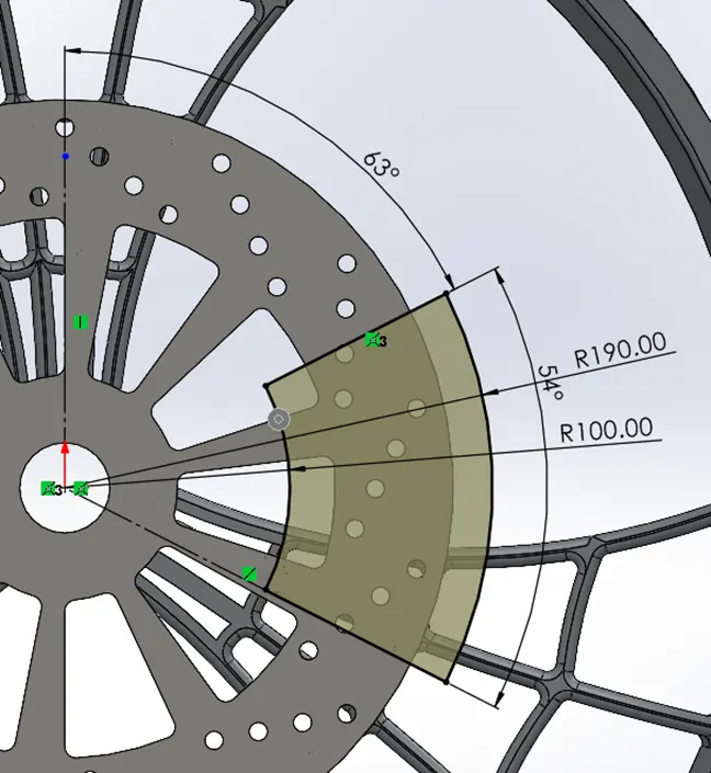
- The profile is extruded for 19.5mm in direction1 and 10.5mm in direction2.
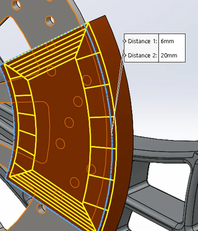
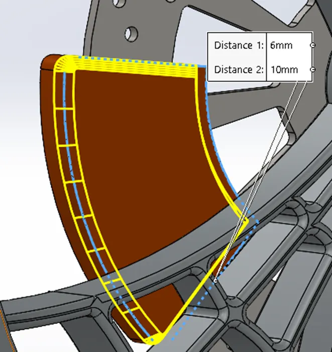
- Add chamfer to the edges with 6, 20mm to one side and in opposite side the dimensions are 6,10mm
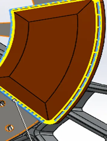
- Add a fillet to four corners of 8mm and an edge of 4mm.
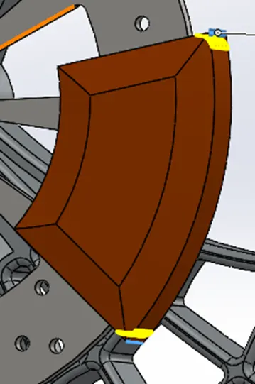
- The next step is to create a tire revolve
- On the top plane, sketch the profile of the tire’s section, and revolve around the horizontal axis.
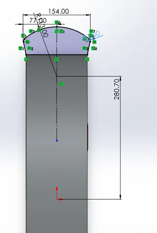
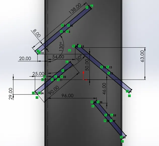
- Then tire grip sketch is made on the top plane.
- Click on extrude cut, use offset of 450mm and offset from the surface, select the outer face of the tire.
- Enter the distance of 4mm, reverse it to check whether the grip profile cuts the tire.
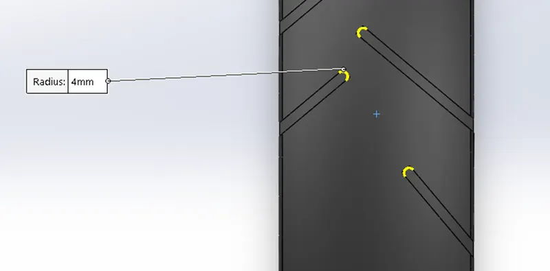
- Add fillet of 4mm to grip profiles.
- And pattern the cut extrude, around the tire with 14 instances.
- Do not merge the bodies. The tire, rim, caliper, and disc rotor are different bodies.
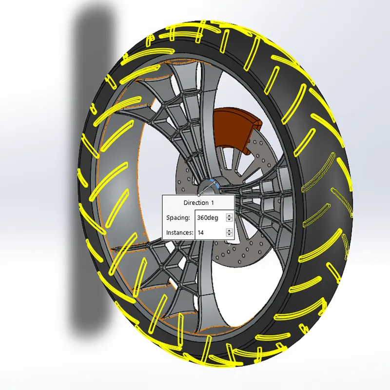
7. Rear Wheel:
The design of the rear wheel is similar to the front wheel. In addition to the front wheel, the rear wheel will have a chain sprocket.
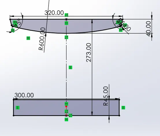
The rim is revolved, followed by rib extrude, spider web design, and trimming the rib to get a curved rib.
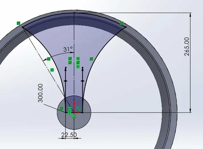
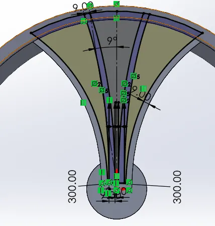
Then the rib is patterned circularly with an instance of 3.
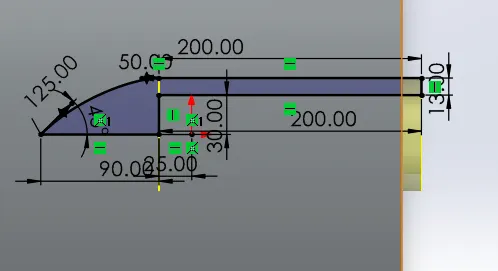
The above sketch is revolved around the horizontal axis
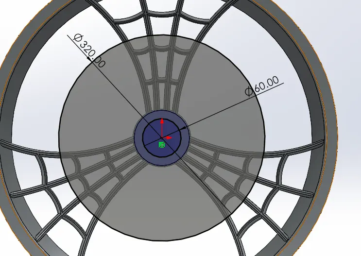
- To get the disc rotor, sketch a circle of 320mm diameter on the right plane.
- Extrude the circle with an offset of 105mm from the plane and a width of 7mm. The merge result option is disabled as this is a separate body.
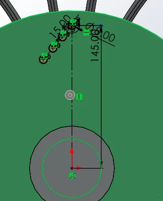
- To get the holes as in the disc rotor, the holes are created and patterned circularly. The no of instances is 14.
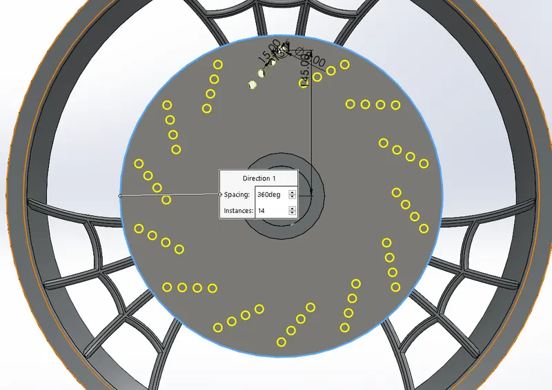
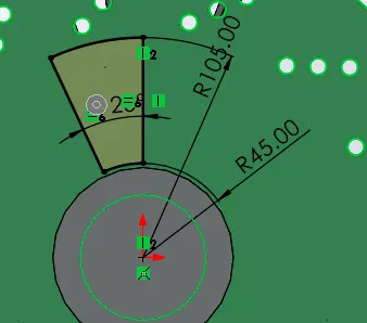
- Fillet of 5mm is added to the internal edges.
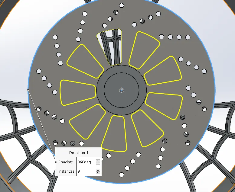
- The above profile is sketched on the face of the disc rotor. Then this sketch is used in cut extrude to remove material. And patterned circularly with 9 instances equally spaced.
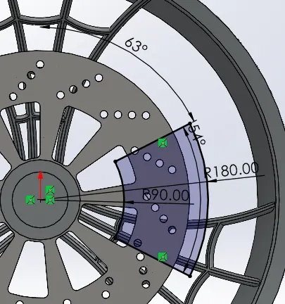
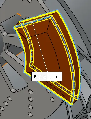
The caliper is extruded by the below sketch with an offset of 3.5mm and a midplane to the distance of 30mm. This followed by adding chamfers to the outside edges of both sides.
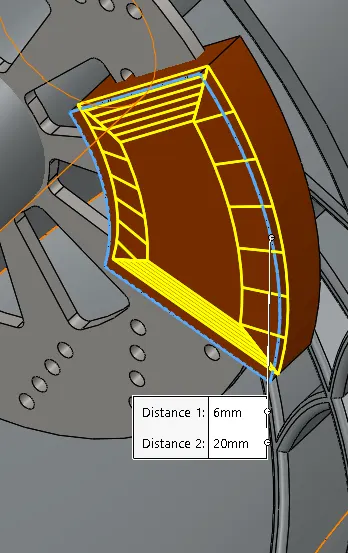
adding fillet of 4mm as shown below
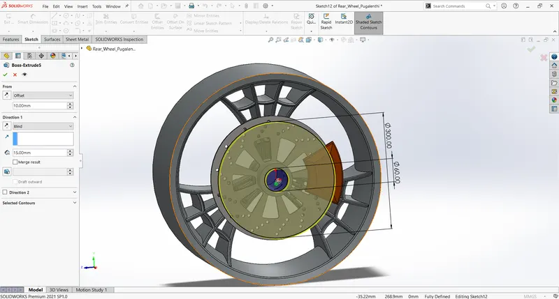
- Design of sprocket is done initially by sketching the circle of outside diameter and diameter of the hole
- then this extruded with an offset of 10mm and width of 15mm.
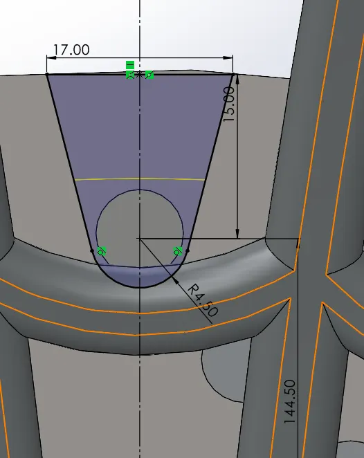
- adding chamfer to the edge of the sprocket (Chamfer dimension 4mm, 45deg).
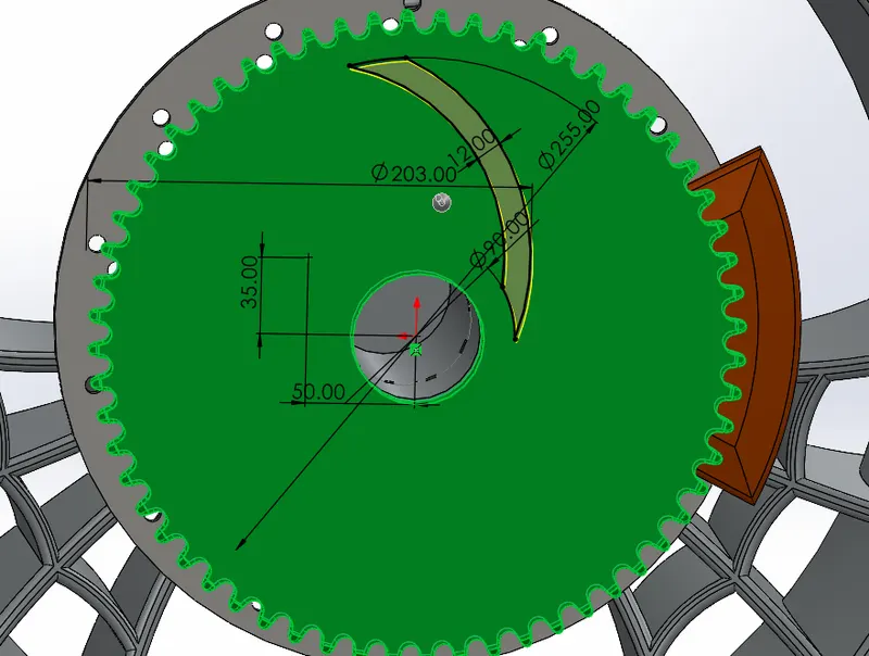
- The teeth profile is done by sketching and cutting the following profile and then patterning them around the circle.
- Circular pattern specifications- No of instances is 60
- then the internal profile is sketched, extrude cut, and followed by patterning them.
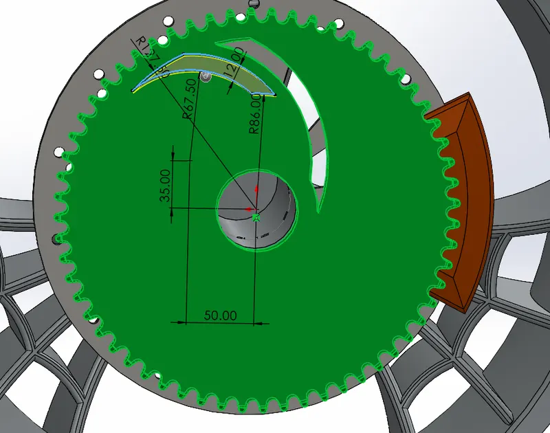
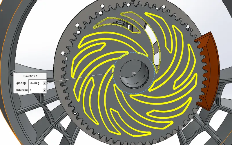
**The important thing to maintain is to have correct merge to bodies.
- Next, the tire profile is revolved, then the grip profile is removed and patterned around the tire. Make sure that bodies are not merged together.
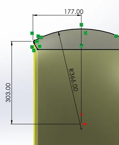
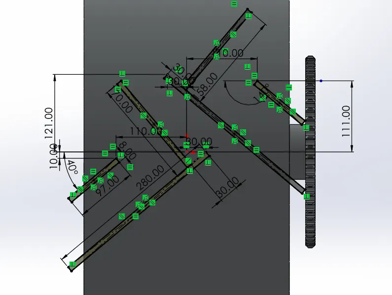
- Follow the same steps (Front Wheel) in extrude cutting the tire profile.
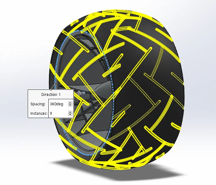
- Pattern them circularly with 9 instances.
8. Chasis :
The chassis is an important part of the vehicle as it holds all other parts of the vehicle together.
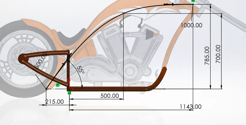
Chassis is designed mainly with project curve and swept bose features, The splines are reverse engineered from the picture of the chopper. The picture can be brought into the sketcher using a tool called sketch picture. And a transparency value of 0.4 to 0.6 is given so that both sides of the chopper can be viewed easily.
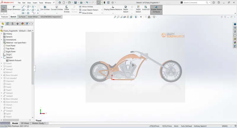
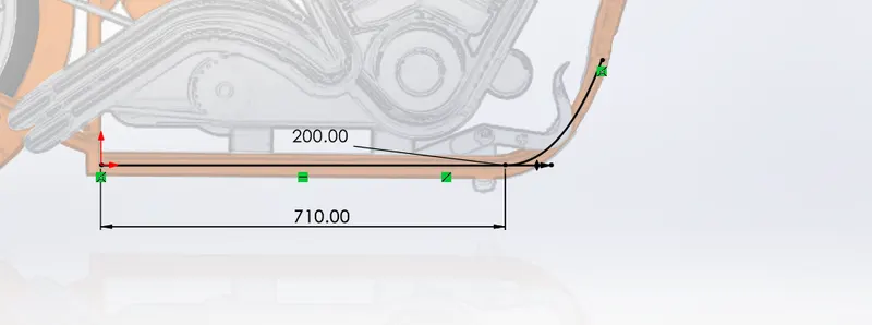
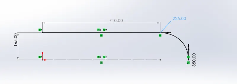
- The two curves are used to bring the projected curve, which is then used as a path for sweeping hollow circles.
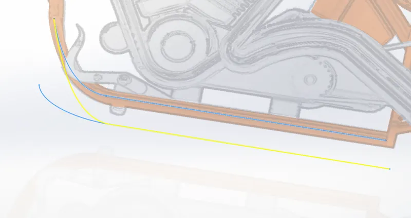
The projected curve is shown using a yellow line.
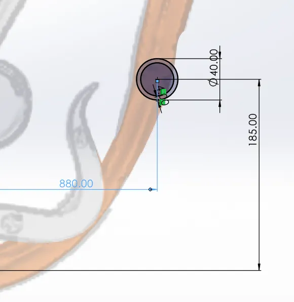
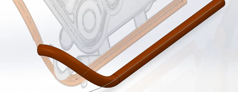
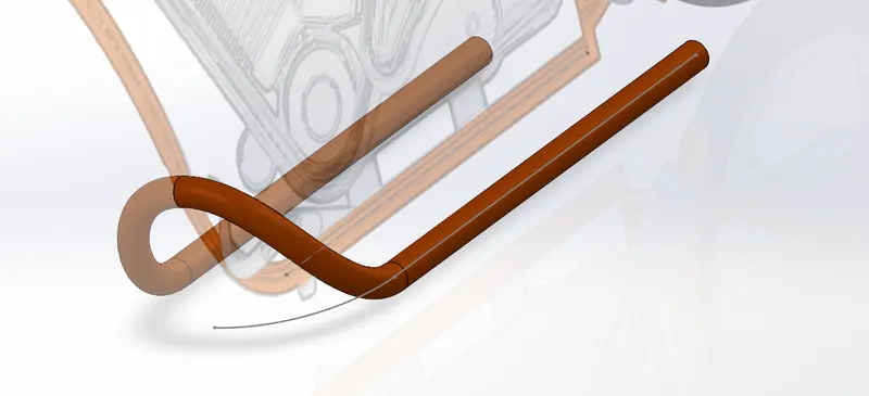
Then the above sweep is mirrored with the front plane
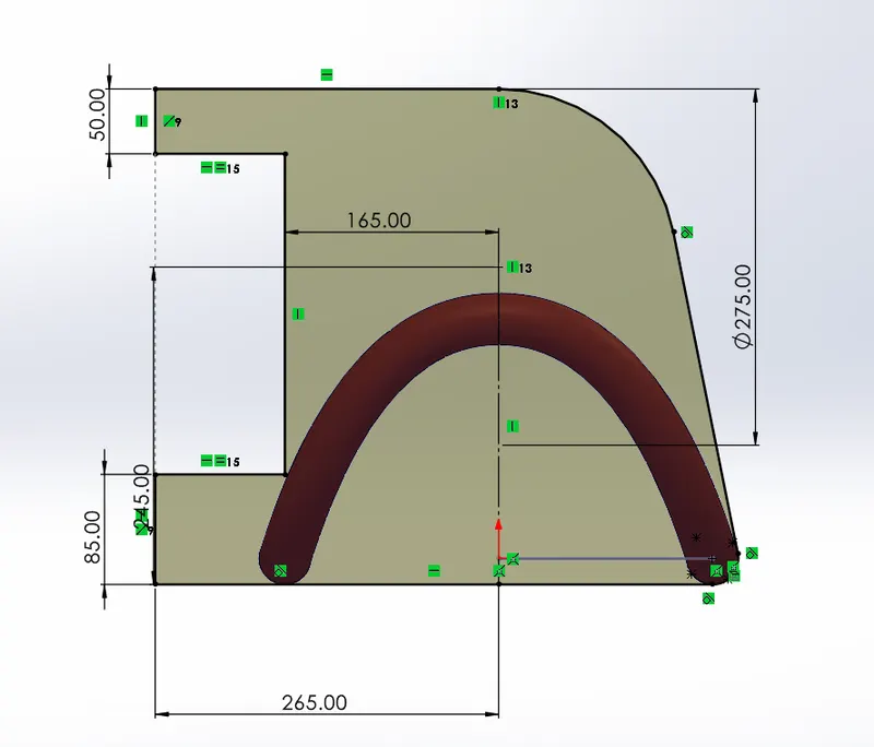
The above sketch is drawn on the right plane connecting two sweeps and extruded for a distance of 22 mm and enabling merge result as the chassis acts as a whole body.
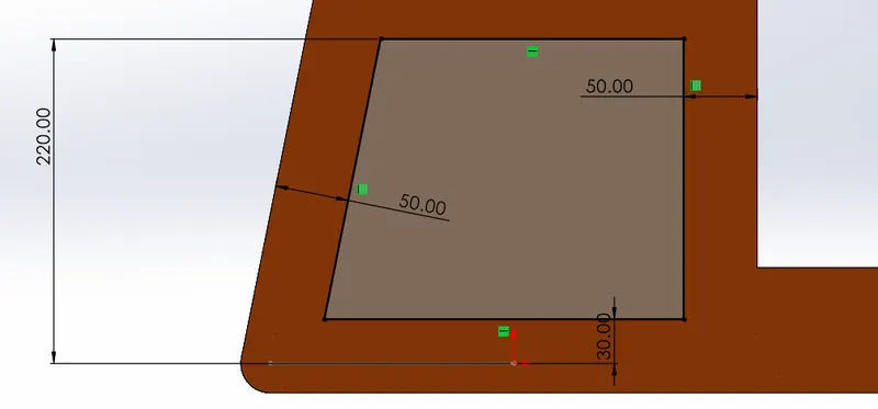
Select the back face of the last extruded feature to sketch and use extrude cut.
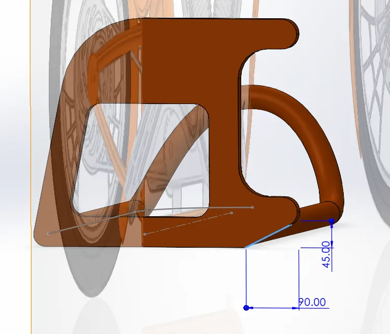
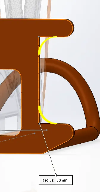
Add chamfer to the edge shown above and add a fillet to the internal and external edges as shown.

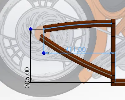
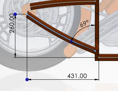
Add a plane offset of the front plane. Use the above two sketches and sweep them with a hollow circle of dimensions same as used before for the sweep.
use the below sketch and extrude for the length of 44mm. and from the end face of this extrude a circle of 60mm diameter to the length of 223mm.
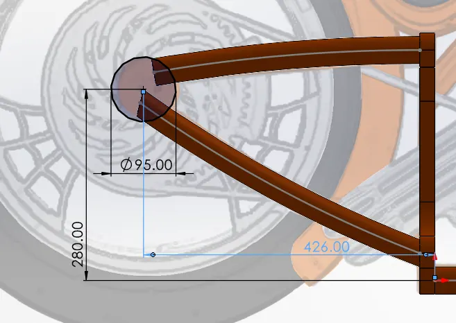
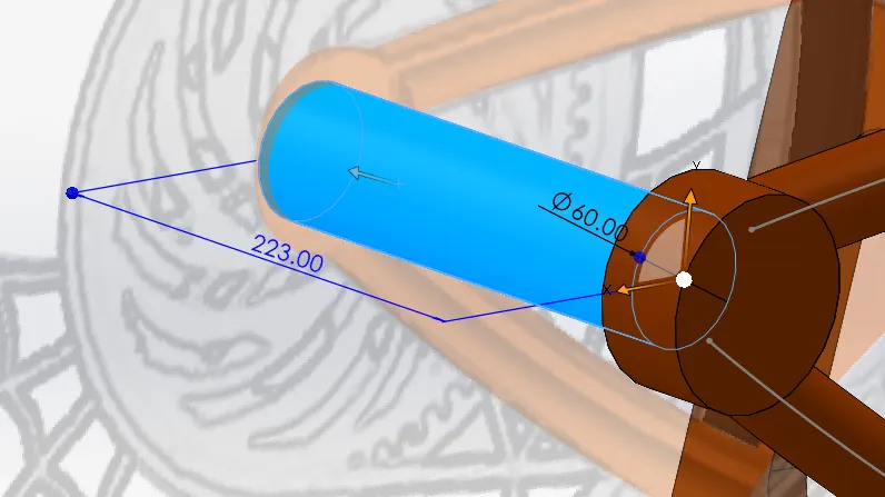
Create a three-point spline with reference to the picture and as per dimensions shown. and this spline is swept with a hollow circle of the same dimension as used before.
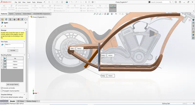
The above image shows a split tool that splits the excess sweep and removes them.

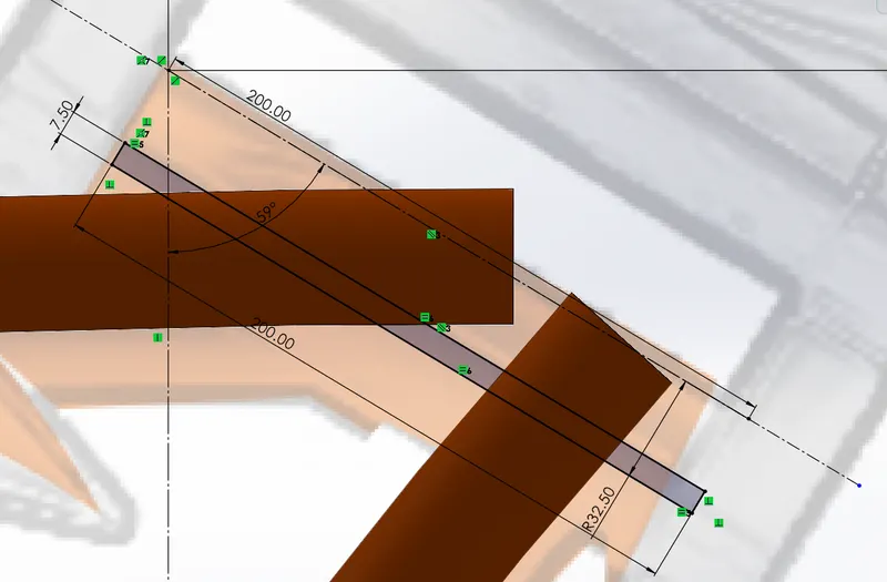
The sketch is revolved around the axis shown and this geometry holds the front fork.
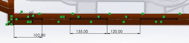
The above sketch is extruded till the next surface as this base holds the engine.
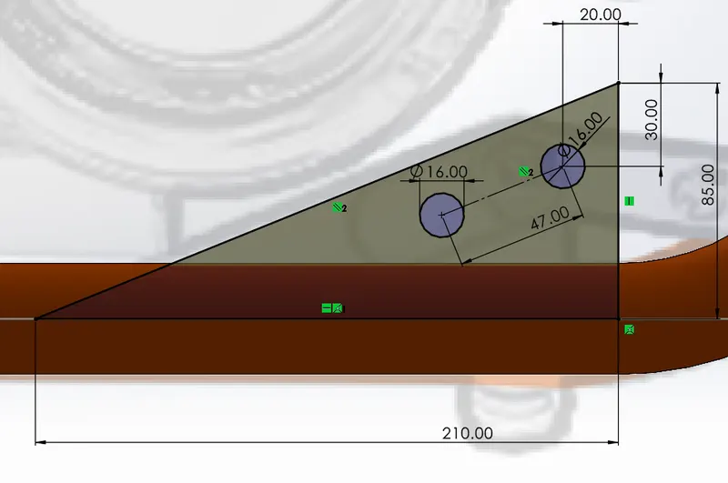
This is the mounting plate for the pedal and extruded to the width of 10mm and mirrored with the front plane for holding pedals on both sides.
The last feature to add to the chassis is to create a boss for mounting the kickstand. The below sketch is made in the right sketch and extruded to the length of 44mm.
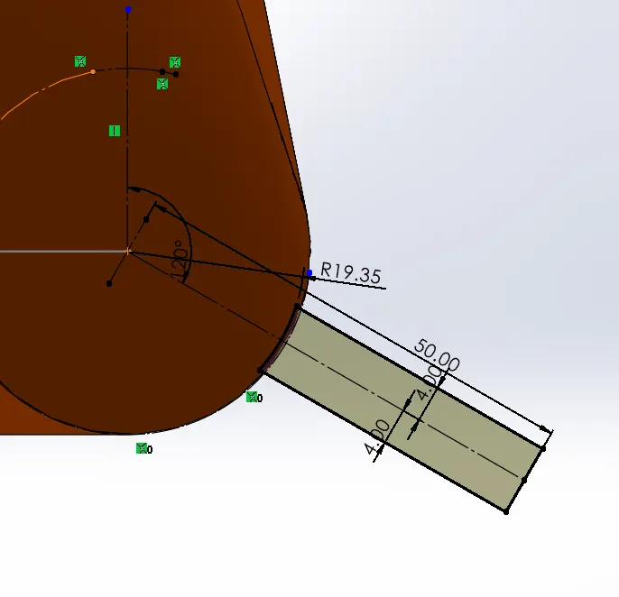
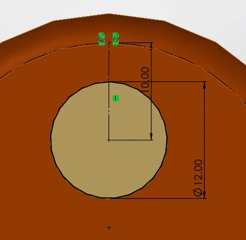
A circular boss of a diameter of 12mm is removed so that kickstand can be mounted into this hole.
Add necessary fillets to the geometry.
9. Chain:
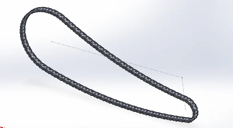
The chain can be designed in the following ways:
- First sketch the profile through which the chain passes.
- create the elements of the chains as blocks.
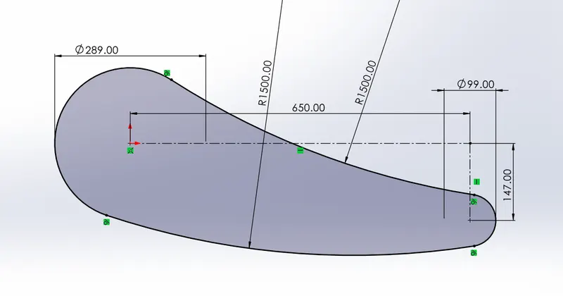
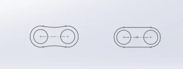
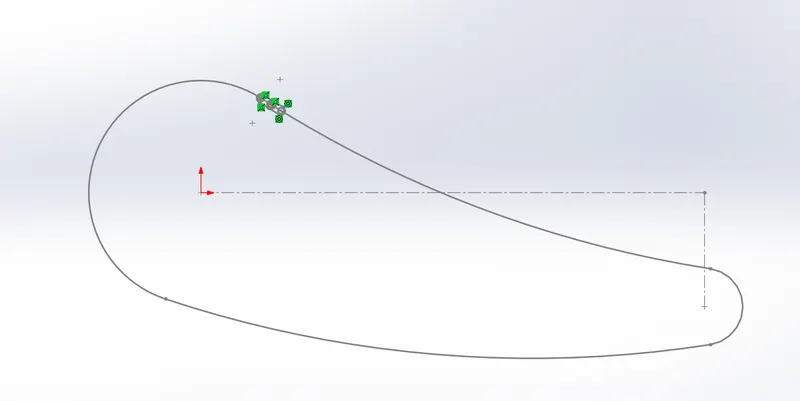
The above blocks are arranged such that the constraints are coincident with the curve and fully defined.
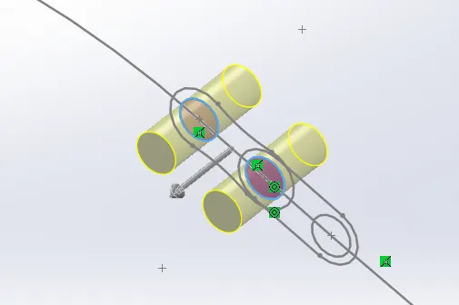
The circles in the pin are extruded using a midplane for a distance of 25mm. And with the same sketch, the remaining section is extruded with an offset of 9.5mm and for the width of 2mm. The merge result option is disabled for every extrude hereafter since all are different bodies.
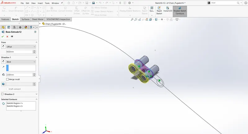
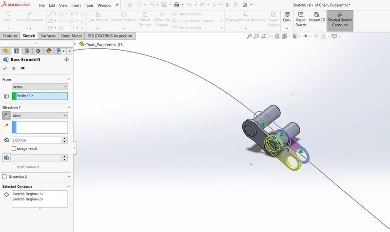
Then we create a curve-driven pattern by selecting only this curve and with 20 instances. We create only for this curve is because of the transitions between the curves. At the transition, we again add new blocks extrude them, and pattern them with curves. We repeat the process till the curve completes.
10. Front Fork:
The front fork has 3 bodies. They are 2 headlamps and fork assembly.
First, half of the fork is designed and mirrored the remaining half along with the headlamp.
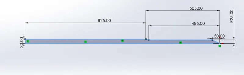
The sketch is drawn on the front plane and revolved around the horizontal line.
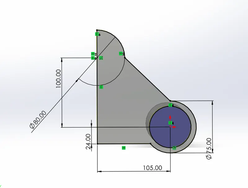
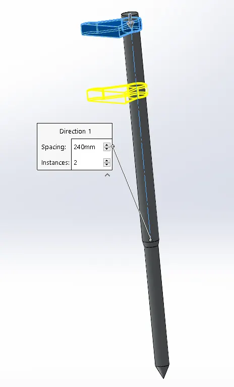
On the top of the circular end, use the face to sketch and sketch the above sketch and extrude with an offset of 20mm downwards for the width of 40 mm and patterned along the axis of the fork with a spacing of 240mm.
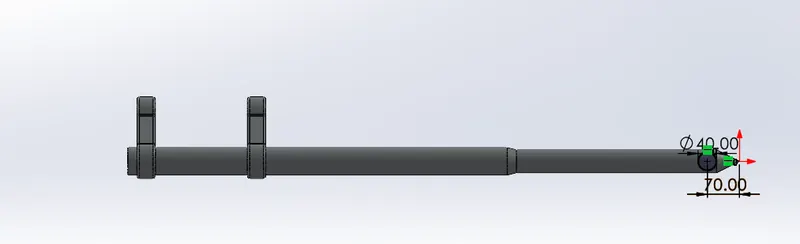
Then to create a shaft for holding the front wheel we need to create a sketch on the top plane consisting of the circle as shown and extrude till the half surface.
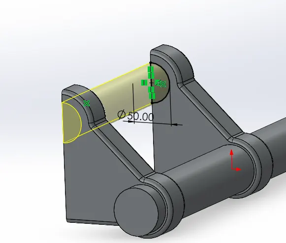
Use the face to sketch and draw a semicircle of 50mm diameter and extrude till the next surface as shown.
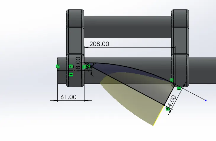
Next is to create a headlight which is a separate revolved body. The sketch is created first and revolved along the inclined axis and moved with the help move/copy tool to the front position of the fork.
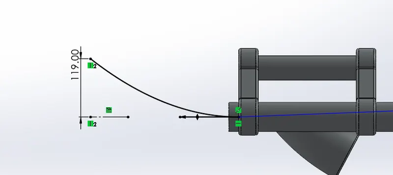
Next is to create a handlebar, the two splines that create a smooth curve using the project curve option to create a sweep.
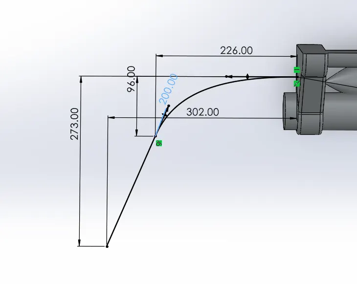
A plane at the end of the spline is created, a sketch is created for revolving that looks like a handle.
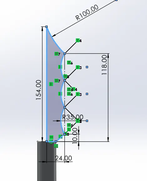
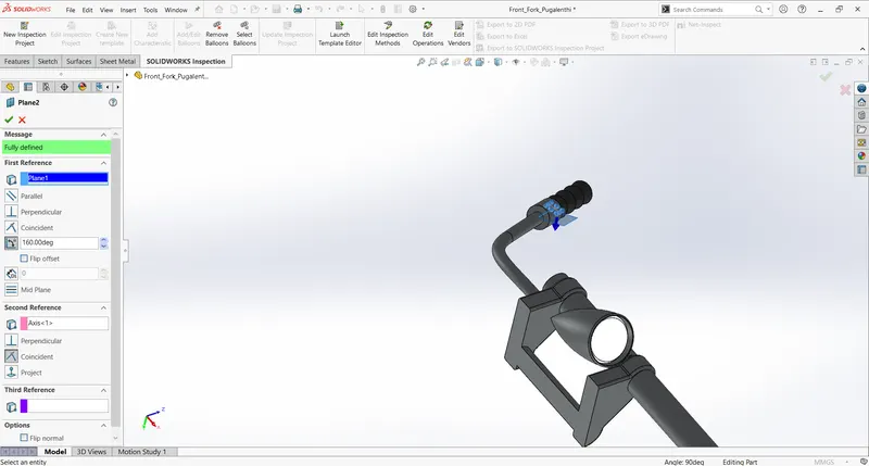
Then to a brake lever to the model, an inclined plane of 160deg along the axis shown is created and the below drawing is sketched on that plane and extruded 15mm.
Adding necessary fillets to the geometry and mirroring it. then bodies without headlight are combined as a single body.
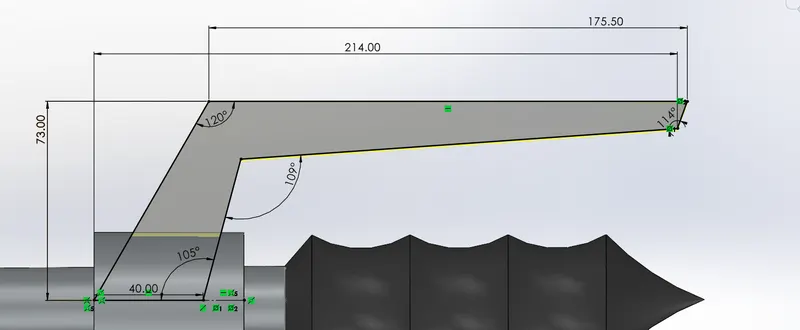
Gas Tank:
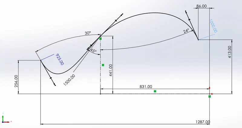
First, the actual picture of the chopper is added to the model using the sketch picture tool and on the front plane, 3 point spline is created that represents the outer curve of the gas tank and applies dimensions to the curve close to that. The gas tank is designed with surfaces.
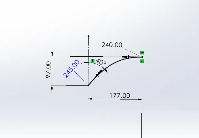
The above sketch is made on the right plane intersecting the spline and sweeping through the curve.
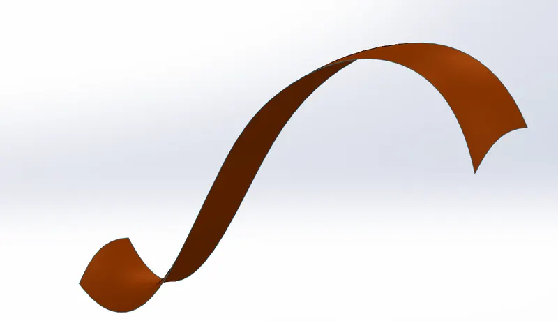
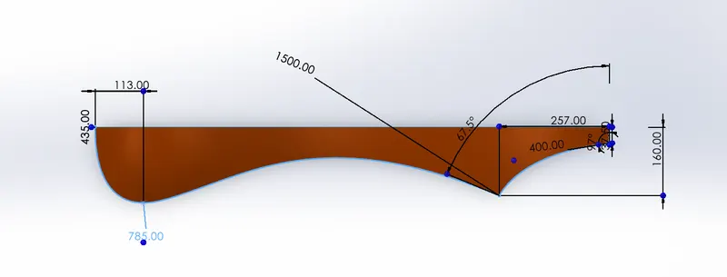
The sketch on the top plane is used along with the surface trim option to get the desired shape.
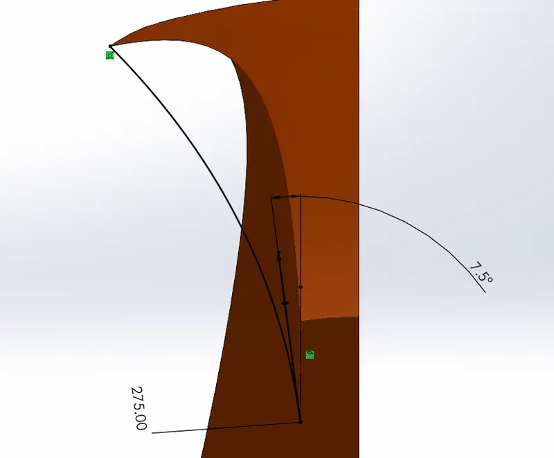
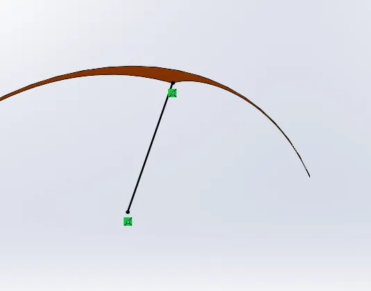
The above sketches are made on the right and front planes and are projected through the project curve option.
Using the surface loft option, the edges are selected and a lofted surface is created.
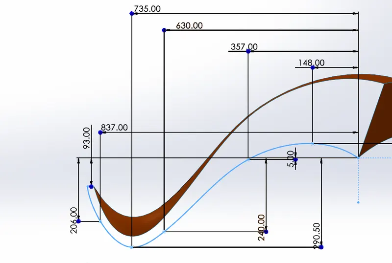
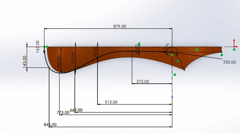
The above two curves are created on the front and top planes and they are projected using the project curve option and with the boundary surface option, the edges are selected to get a surface.
And they are mirrored along the front plane and merged using the surface knit option.
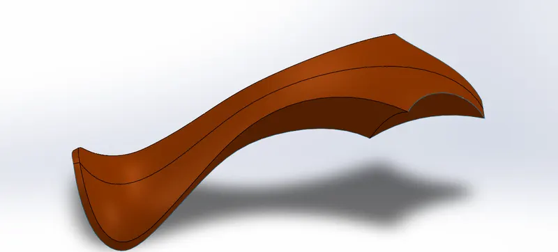
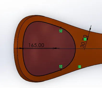
the above sketch is made on the top plane and by selecting the faces and the sketch, using the split line tool the lines are projected on the faces selected.
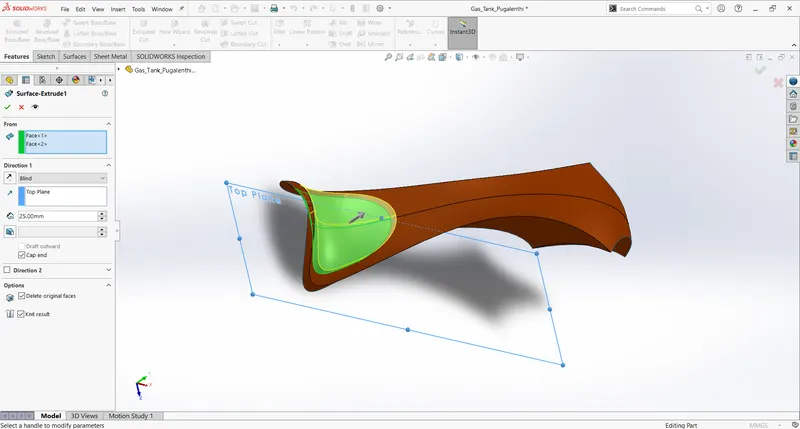
now by using surface extrude, the split faces are selected and extruded for 25mm. Also, select cap end, delete original faces, and knit result to have a closed geometry and combined geometry.
The bottom tank are closed using a surface loft tool and then they are made as solid and they are shelled for the thickness of 3mm.
Engine:
The engine here is a single body since all the model here is a cosmetic model.
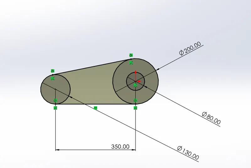
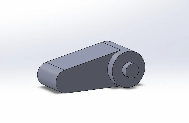
The above sketch is used with boss extrude to get the below 3d model by repeatedly using the same sketch.
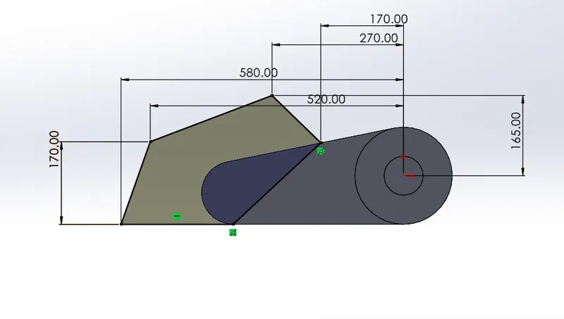
On the front plane, the below sketch is made, extruded and fillets are added.
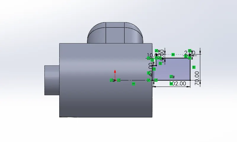
On the right plane, the sketch is revolved along the horizontal line.
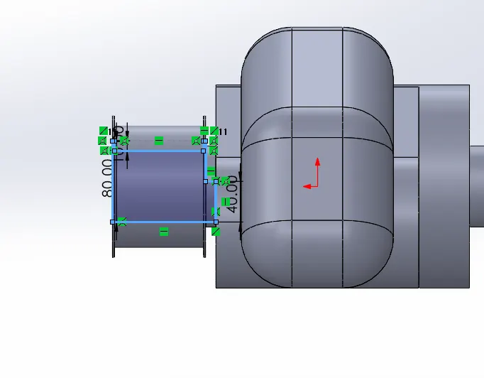
Similarly, the above sketch is also revolved as same but a new plane is created using a temporary axis on the predesigned geometry.
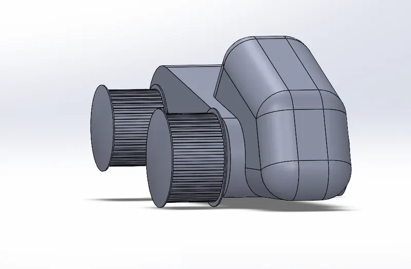
A rectangle of 5x4mm is drawn, extruded, and patterned for both the revolved geometries. Also, a dome is added to the ends.
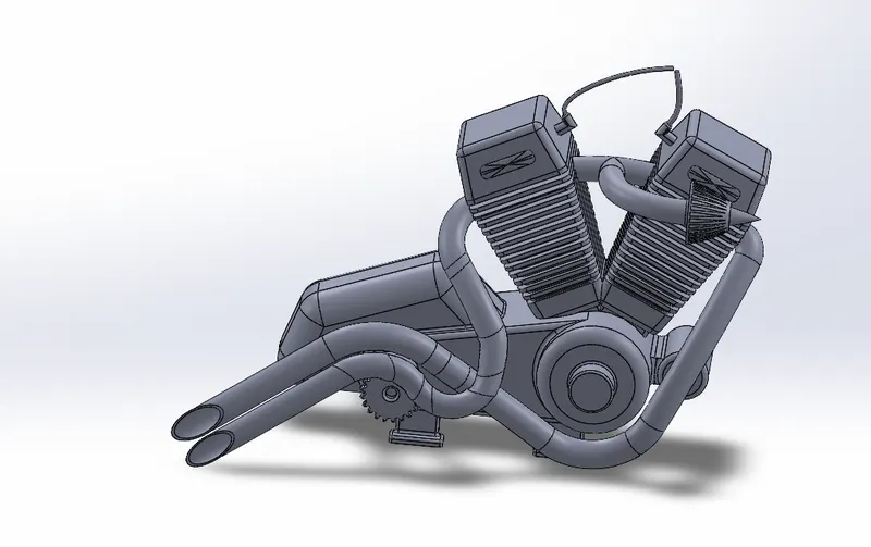
Only one cylinder on the right side is first generated using boss extrude with taper and fins are generated using cut extrude tool. and the other cylinder is mirrored.
The exhaust and inlet pipes are made using project curves and splines.
Adding appearances to the geometry:
In the edit appearances option apply the following paints and materials to the geometry:
- Under edit appearances > Rubber > Gloss > Gloss Rubber for both the tires and cables.
- Under edit appearances > Painted > Car > Siena for gas tank, chassis, fenders, and calipers.
- Under edit appearances > Metal > Chrome > Chrome Plate for front fork, rims and engine.
- Under edit appearances > Lights > Area light > for inside of headlights.
Assembly:
Open SolidWorks > New Document > Assembly > Units MMGS
- Under Insert Components, browse for the part to open.
- First I insert the chassis
- the front plane of the chassis and assembly is made to coincident and fix the part
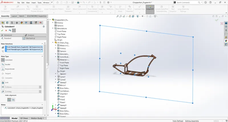
Then Engine is brought into assembly the constraints are :
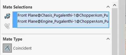
- The front plane of assembly and Engine are coincident
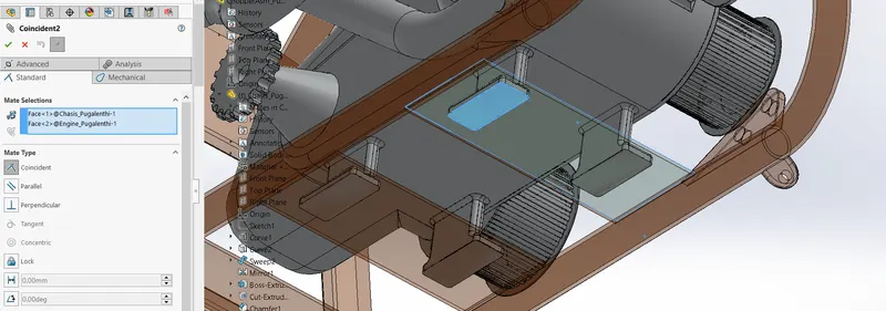
- The bottom face of the engine and a face on the chassis are coincident
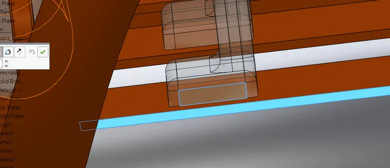
- The selected faces are at a distance of 20mm from the chassis.
The part to be assembled is the pedal. Then mirrored to another side.
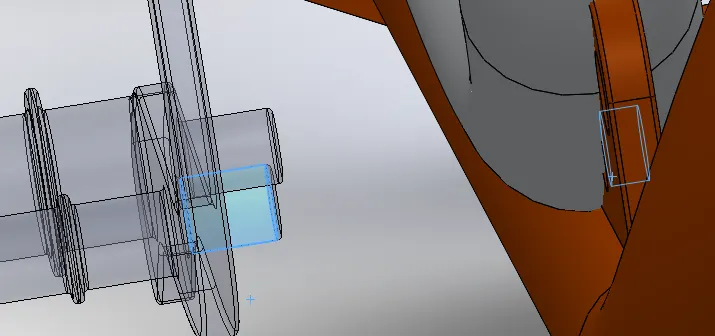
The circle bosses are made concentric with the holes on the chassis and the faces of the pedal and face on the chassis are coincident. And they are mirrored.
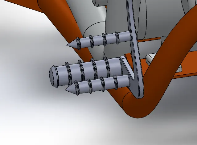
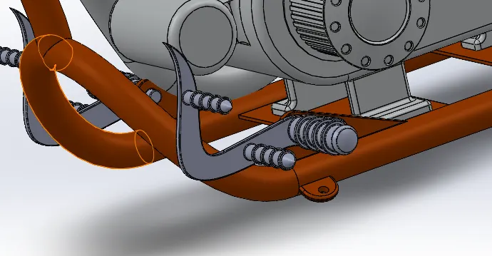
- The rear wheel will be concentric with the shaft for the rear wheel on the chassis.
- The front plane of the chassis and the right plane of the rear wheel are coincident.
- The right plane of the chassis and the front plane of the rear wheel are parallel.
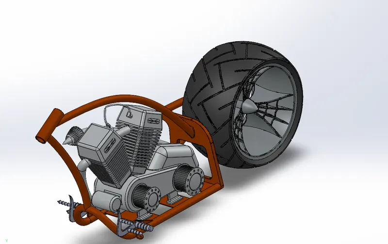
- The rear fender is said to be concentric with the wheel.
- The front plane of the chassis is coincident with the right plane of the rear fender.
- The right plane of the chassis is coincident with the front plane of the rear fender.
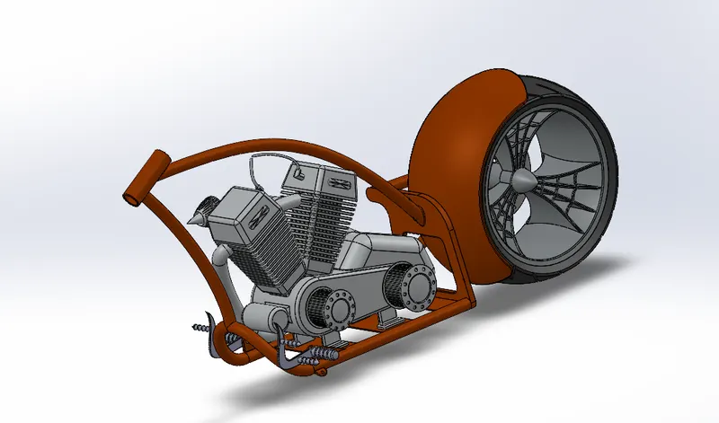
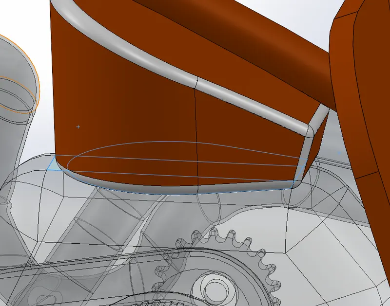
- The front plane of the chassis is coincident with the right plane of the oil tank.
- The bottom face of the oil tank will be coincident with the engine as shown.
- The edge on the oil tank is coincident with the edge of the engine.
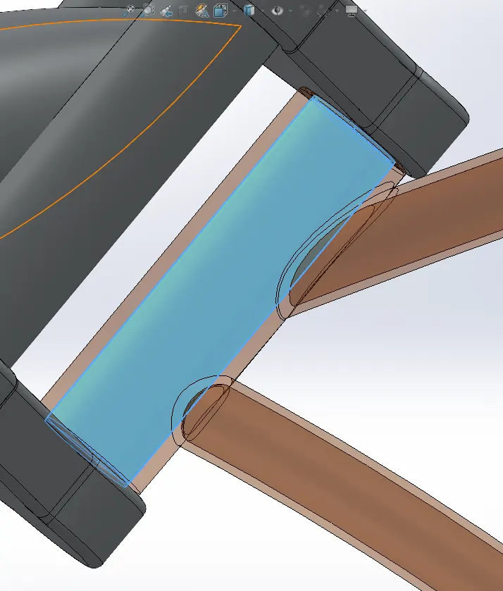
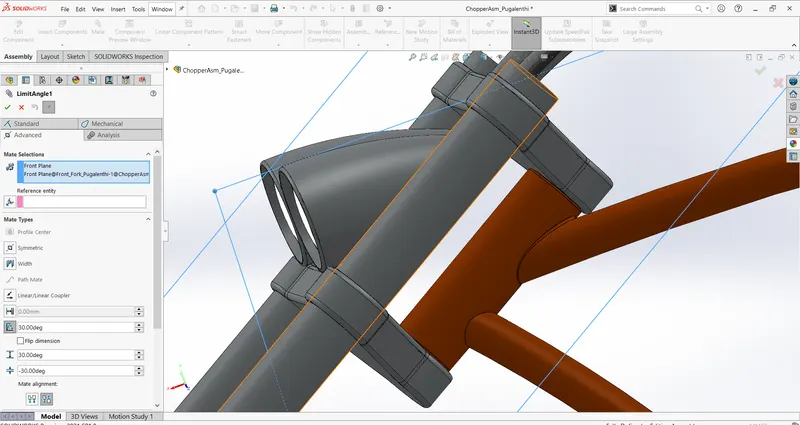
- The fork is said to be concentric with the faces selected.
- Width mate is applied between the faces as shown
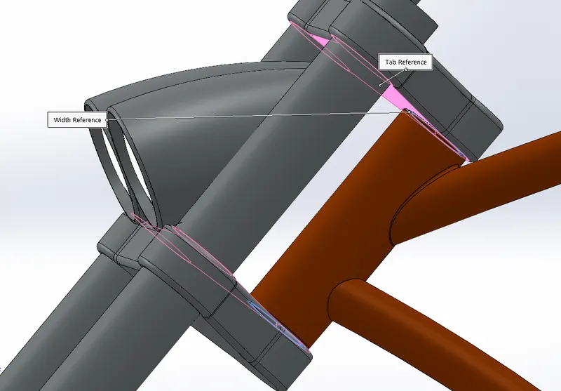
- The turning angle is limited to 30 deg on both sides.
Then assembling the gas tank to the assembly
- The front planes of the chassis and gas tank are made to be coincident.
- Then the position is determined by adding distance from the top and right planes.
Assembling Kickstand:
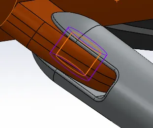
- Applying Concentric relation between the kickstand and chassis
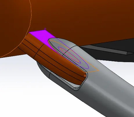
- Applying coincident relation between the faces of kickstand and chassis
- Limiting the angle 0 to 50deg with the back face of the chassis.
Front-wheel assembly:
- The front tire is coincident with the shaft in the fender
- The right plane of the wheel and center plane of the chassis is coincident.
- The top plane of the chassis and front wheel are coincident
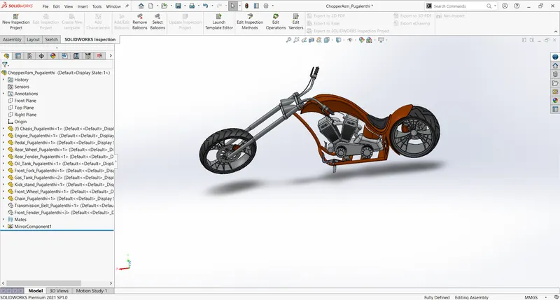
Transmission belt assembly:
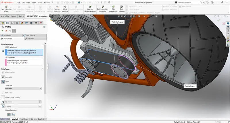
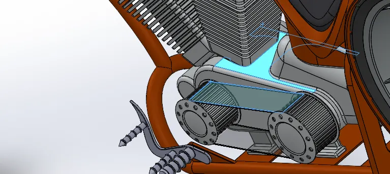
- The width mate is used as shown.
- The larger diameter is coincident with the larger one.
- Angle constraint to the faces as shown.
The assembly of the front fender is similar to the rear fender
- The front fender is concentric with the front wheel.
- The right plane of the fender is coincident with the midplane of the front fork.
- The top plane of the fender is in angle constraint with the top plane of the front fork.
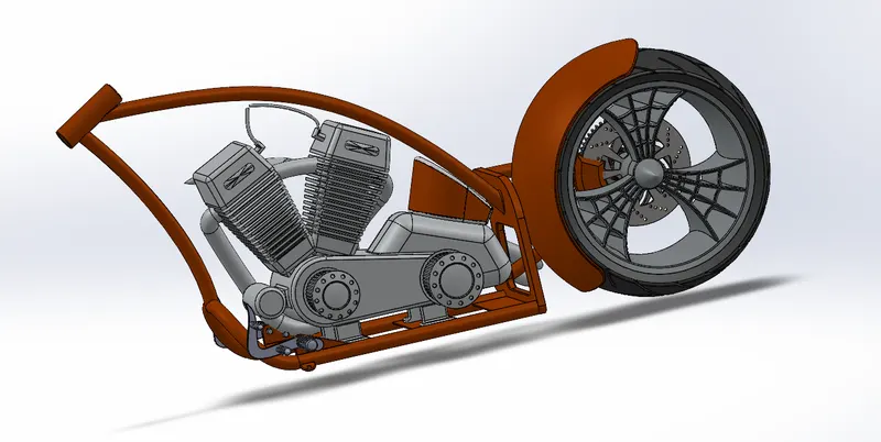
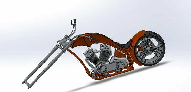
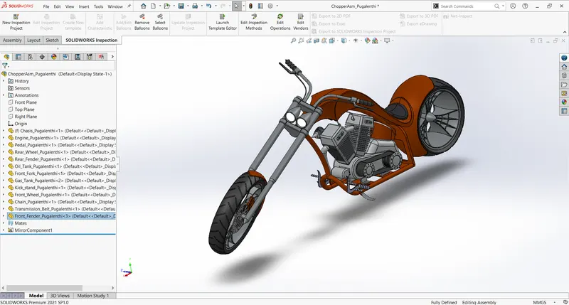
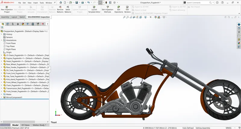
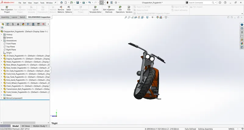
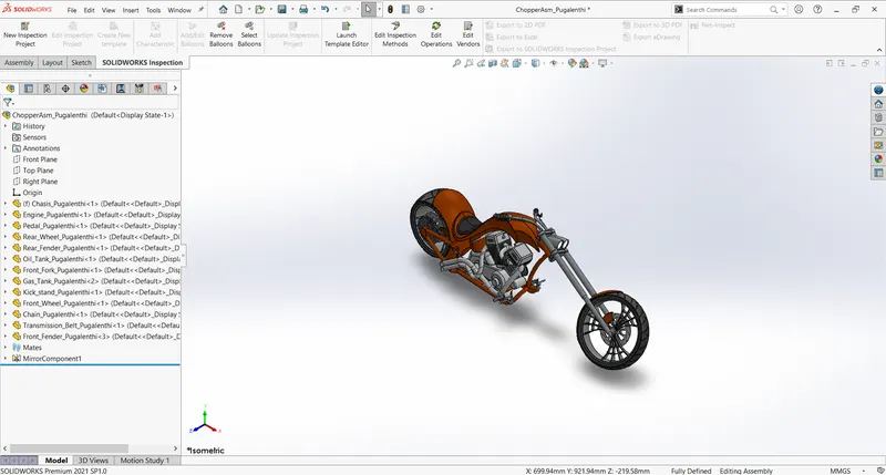
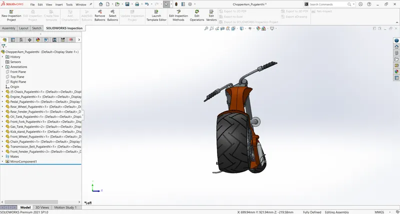
The assembled model is given below:
Rendered Image:
Conclusion:
The design, assembling, and rendering of the chopper was done using Solidworks.
By working on this project, I have a better understanding of various tools, features, mates, editing appearances, and concepts of rendering.
And working with solid and surface complex parts in design, assembling, and rendering is great exposure.