Radar Mast & Final Assembly of Yacht
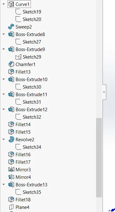
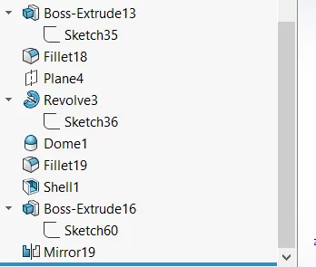
1. Radar Mast
Design and Assembly of Yacht using SOLIDWORKS
Objective:
The objective of this project is to design and assemble the Yacht using SOLIDWORKS.
Introduction:
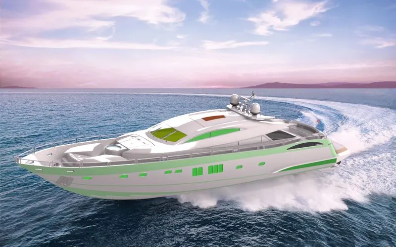
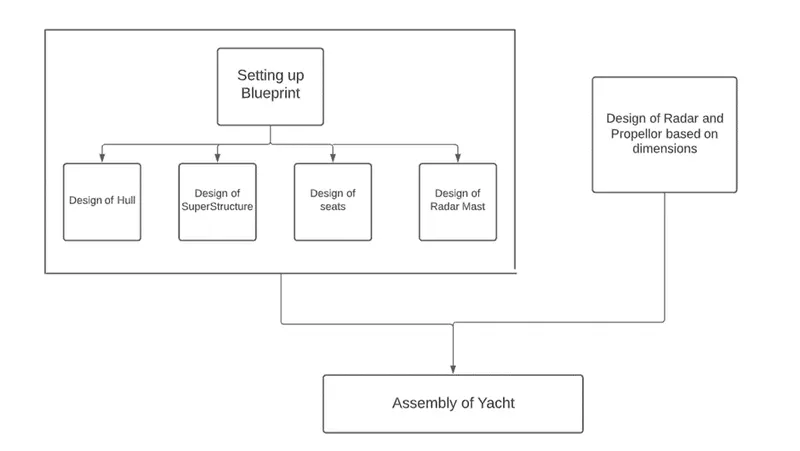
The yacht is a cosmetic model where the main structures are designed by setting up the blueprint of the yacht. The structures are hull, superstructure, radar, Propellor, front, middle, and rear seats. Then these parts are assembled.
Design Methodology:
The approach used here is the top-down approach, the parts are first designed and then assembled.
Steps to be followed before modeling each part:
- Open Solidworks, Click on New, select part, and choose the Document unit in my case I choose MMGS.
Design of Propellor: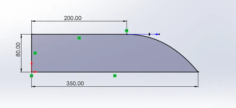
- Select the front plane, create the sketch with the above dimensions and constraints.
- In the features tab, select revolve boss and select the bottom horizontal line as an axis to revolve through 360.
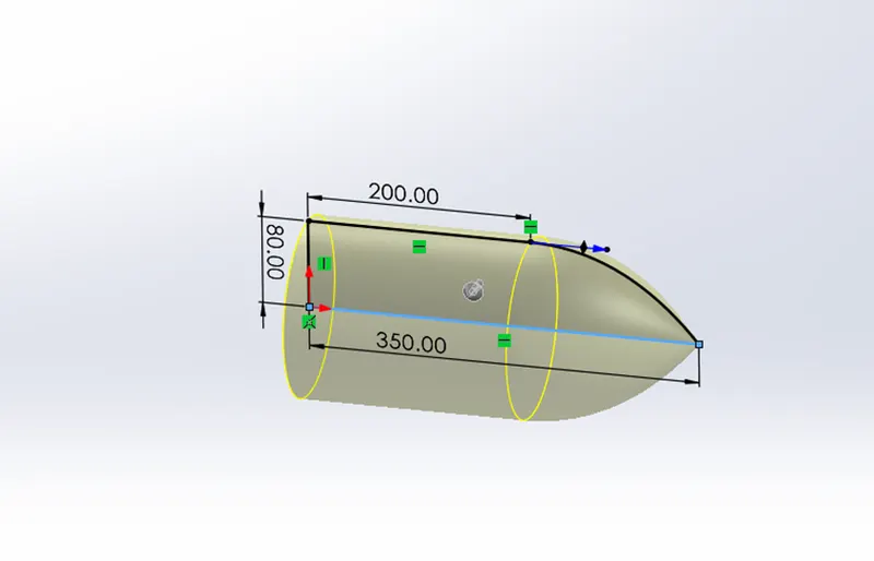
- Create a plane with the first reference as the top plane at an offset of 360mm.
- On the top plane, Create the below sketch.
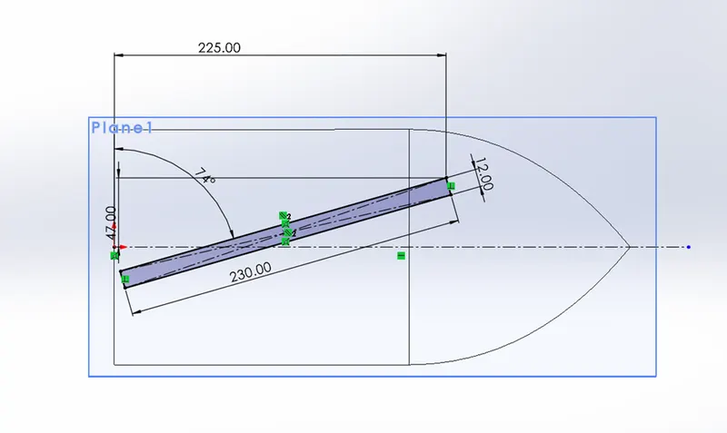
- And on the plane1, Create the below sketch
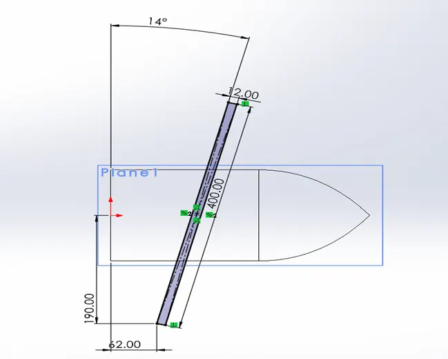
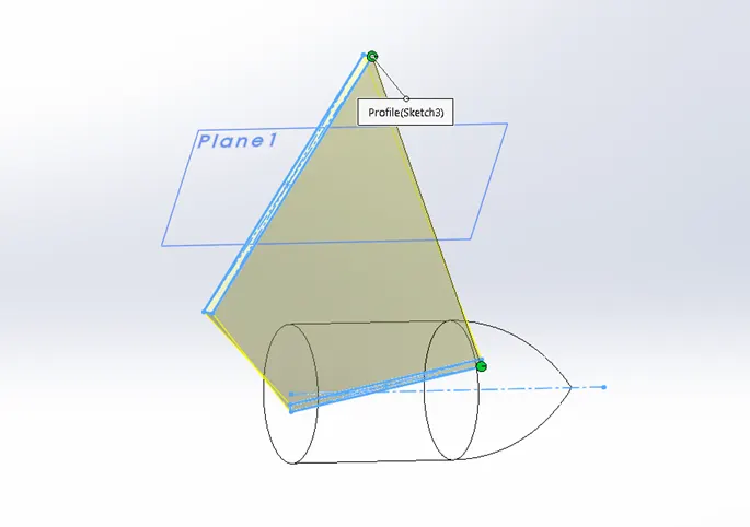
- Use the lofted boss feature, to create a loft between these sketches.
- Make sure that the green dot is on the same side as shown.
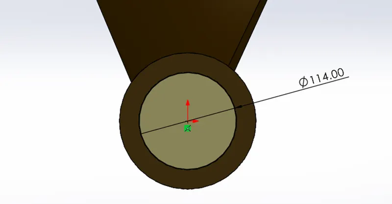
- On the back face of the propellor create a circular-cut extrude of a diameter of 114 mm and for the depth of 210mm.
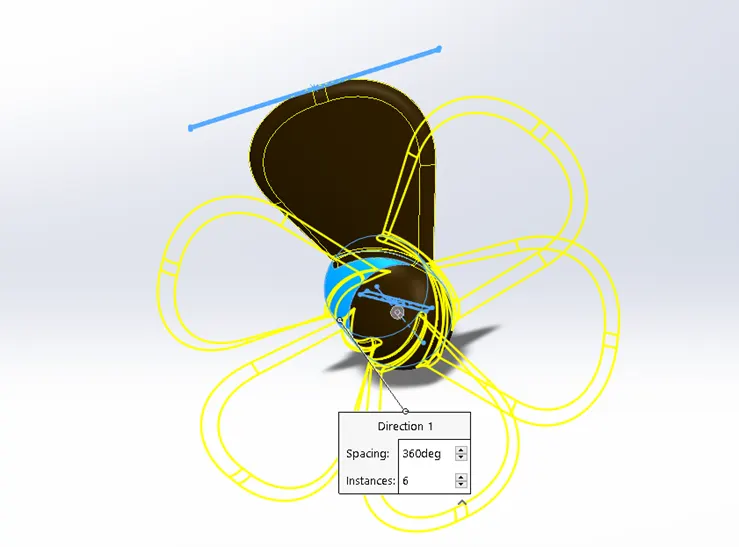
- Create a circular pattern, equally spaced and with 6 instances.
- Design of Radar:
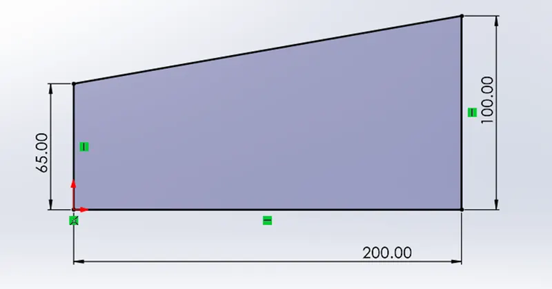
- Select the Right plane to sketch, create a sketch with the following dimensions and constraints. And extrude for the length of 700mm.
- Create an offset of 3mm outwards and extrude for the distance of 10mm
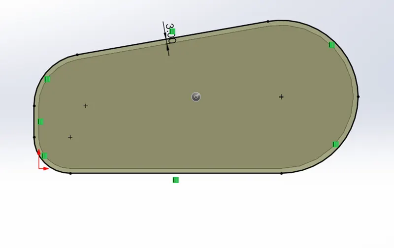
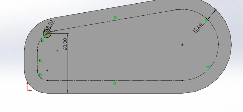
- Create a sketch on the face. Create an offset of 13mm, the outer edges of the face inwards.
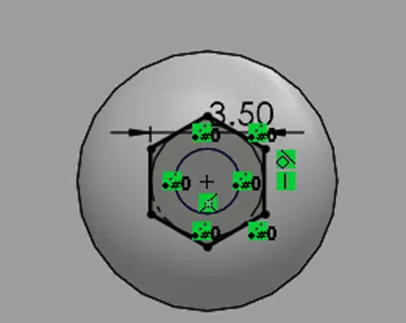
- Draw a circle of diameter 8mm and extrude for the distance of 3mm outwards.
- Add fillets, create cut extrude for the below sketch for the depth of 1.5mm.
- Next is to make a sketch-driven pattern of these extrudes.
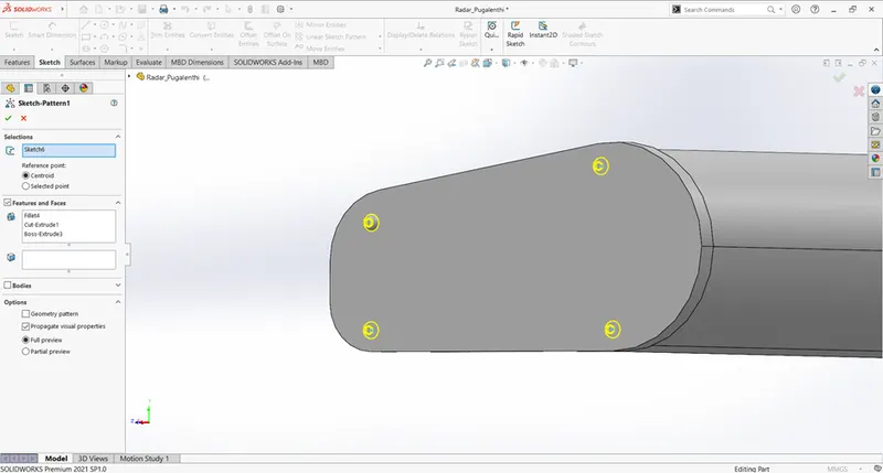
- Make a mirror of these features with the right plane.
Setting up blueprint:
- Rename the top plane as the bottom plane and the right plane as the midplane.
- Create a plane with the first reference as front plane and offset of 32920mm. Name plane 1 as a backplane.
- Create a plane with the first reference as the Bottom plane and offset of 10000mm. Name plane 2 as Top plane.
Design of Hull:
- Create a line and a 3-point spline of equal curvature as shown below closely resemble them in the blueprint.
- Create another sketch with lines and spline that closely reflects the blueprint.
- Apply necessary constraints and dimensions.
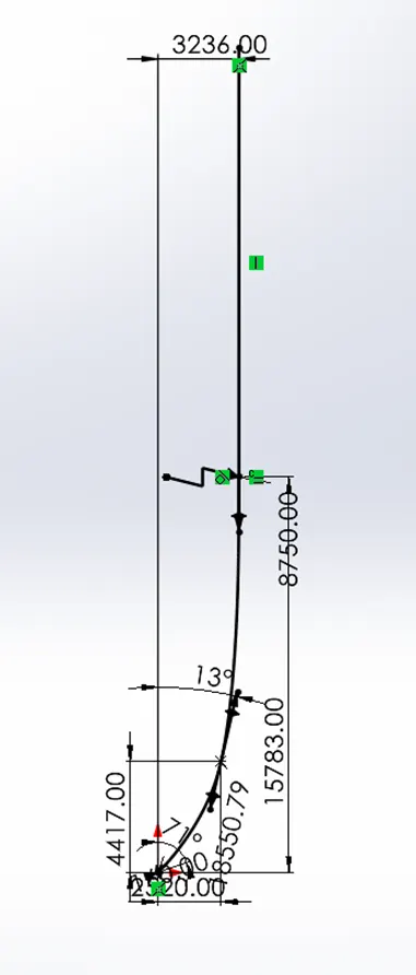
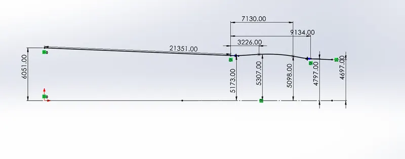
- Make a projected curve with these sketches.
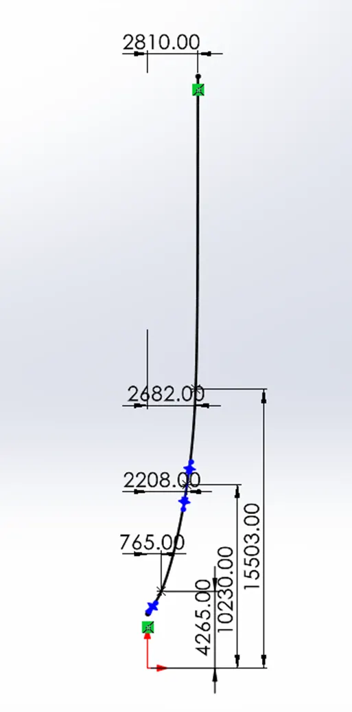
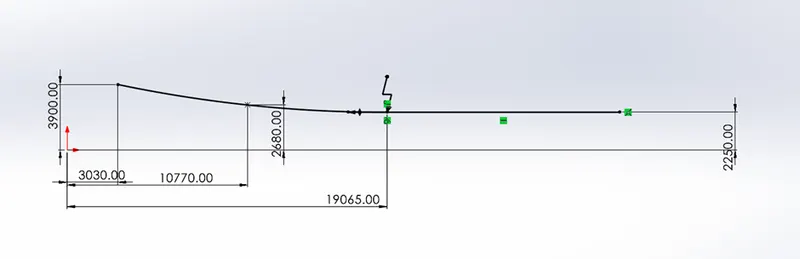
Create another projected curve, with two below sketches.
- Create sketches and make pierce relation between the projected curves and sketch so that they can be used to make a surface loft. Use the above-created projected curves as profiles and two sketches as guide curves.
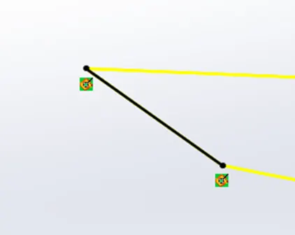
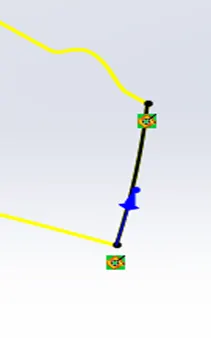
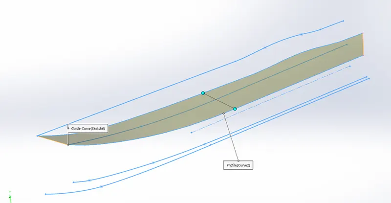
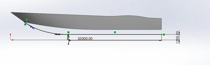
- Create the sketch above sketch on the midplane and below sketch on the backplane.
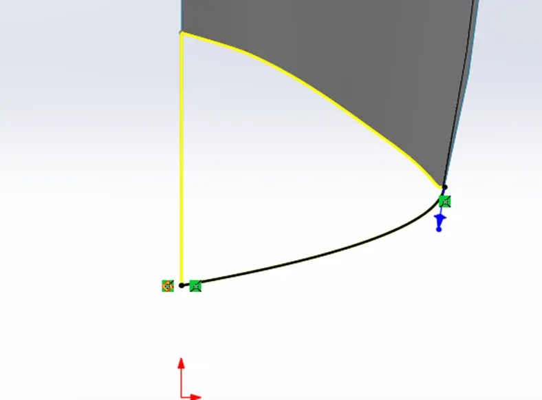
- Use the edge of surface loft 1, sketch as profiles, and above sketch as guide curve to making a surface loft.
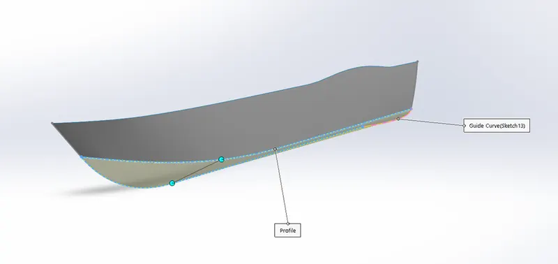
- Create the above sketch on the midplane and use this sketch to trim.
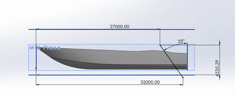
- Create an above sketch on the midplane and create a surface loft with an edge on the surface loft1 and the sketch created.
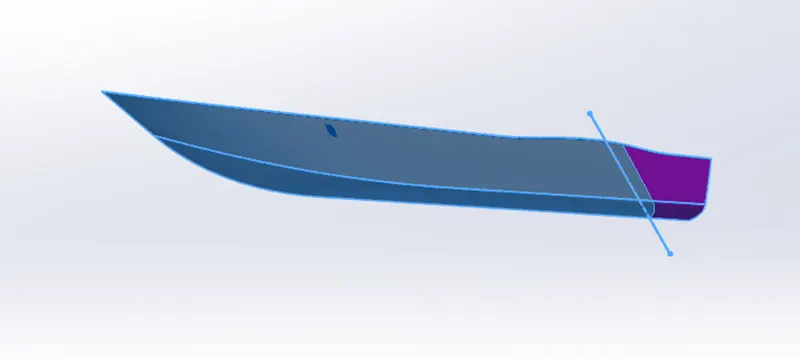
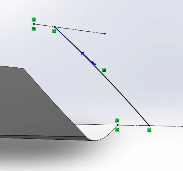
- Create the above sketch on the midplane and use surface extrude to extend for the distance of 5000mm.
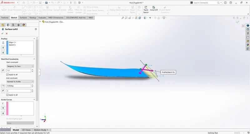
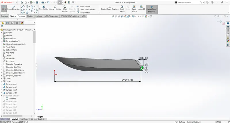
- Use surface trim to remove the highlighted surfaces.
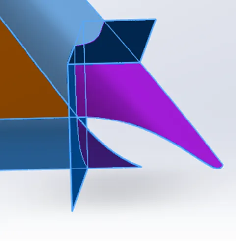
- Then knit all the surfaces together using the surface knit feature.
- To make the base of the hull use surface fill option with patch boundary as the edge of the surfaces and sketch.
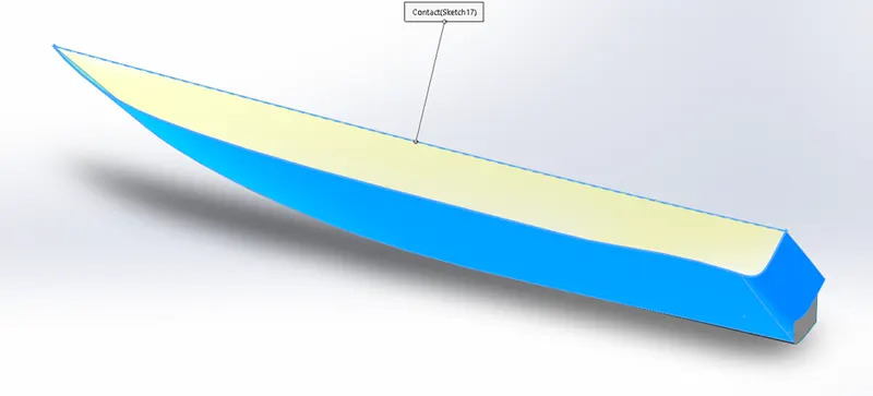
- Knit the generated surface together.
- Create another surface fill, to get the closed surface of the hull. Also, enable merge results and create solid options.
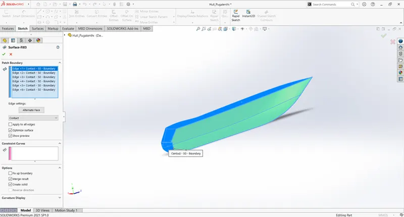
- Create shell without selecting any surfaces so that the shell feature will not be applied to any surfaces making surfaces internally of 120mm.
- In the midplane, create a sketch with the offset of outer edges inwards of 50mm.
- Extrude the sketch up to next.
- On the midplane, create a sketch as shown. And extrude for the distance of 2734mm.
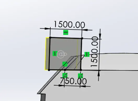
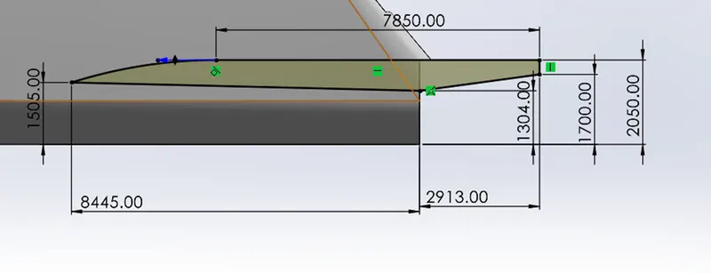
- Use 2D sketch on the midplane, and extrude 3070mm.
- Use a plane from references to create a plane at an offset of 5000mm from the midplane.
- And create a sketch for extrude sketch from the offset as hull surface.
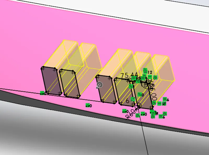
- Repeat the same steps for making windows on the hull surface.
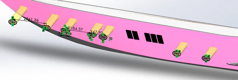
- On the plane1 create straight slots and use extrude cut feature
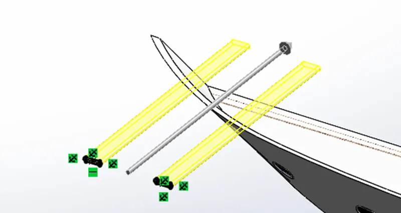
- Repeat the same steps for making windows on the hull surface.
- On the plane1 create straight slots and use extrude cut feature
- As shown above, create a sketch on the top plane and create steps close to that in the blueprint.
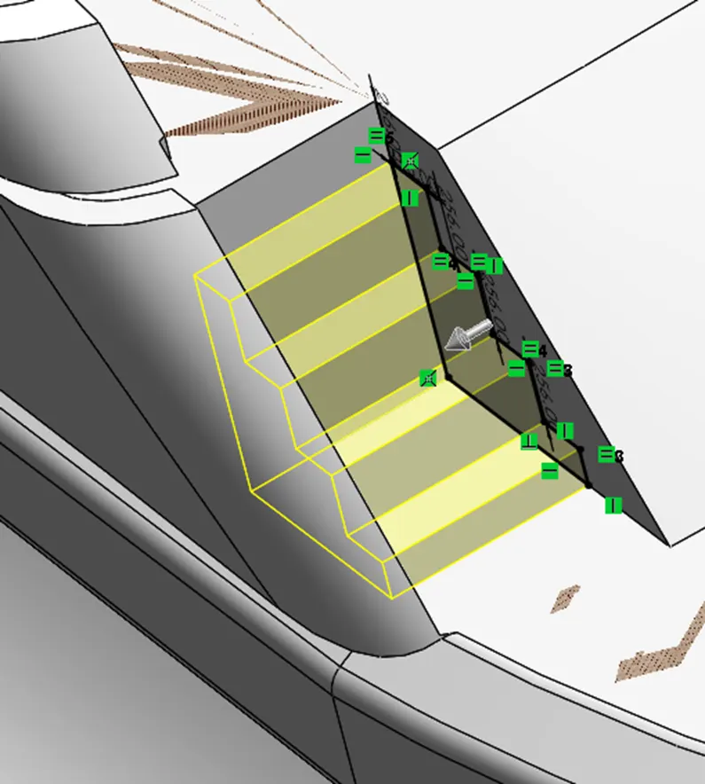
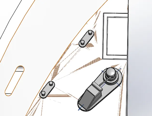
- Create the above-shown bodies using a blueprint and using the linear pattern for creating multiple bodies.
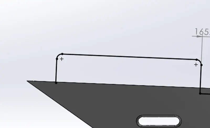
- Create sketches like shown on the midplane with the help blueprint and also use another sketch on the top plane to make an offset of the outer edge of the hull.
- Use the projected curve feature, to make a projected curve out of the sketches.
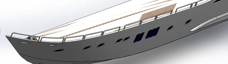
- Once done making all these instructions from the blueprint, use the mirror tool to make the remaining part of the hull.
- Add given appearances and decals to the model.
Design of front, middle and rear seats:
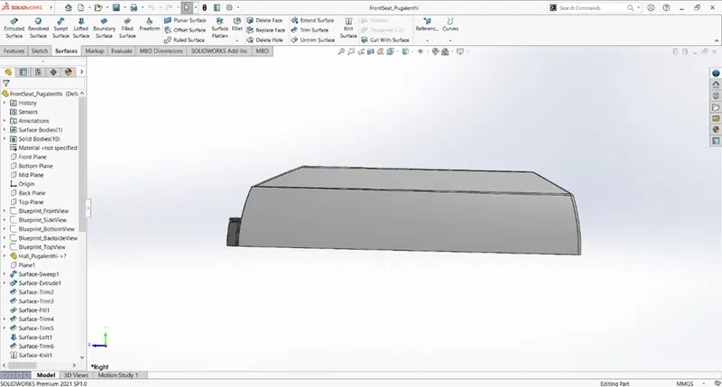
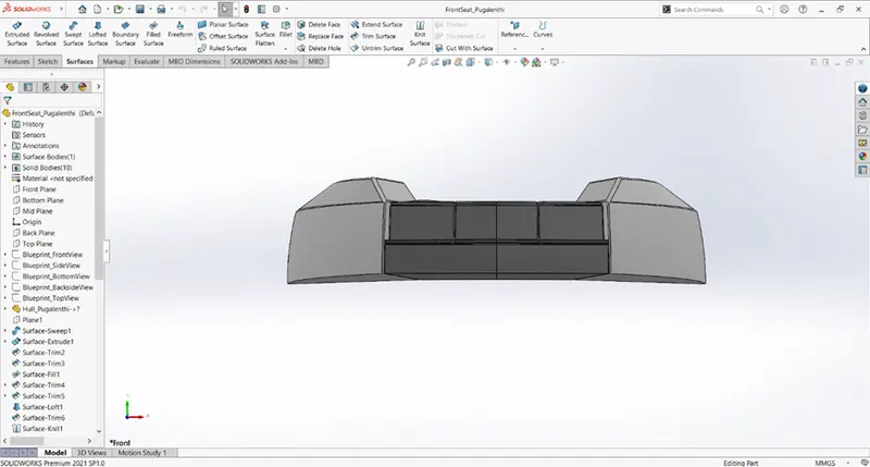
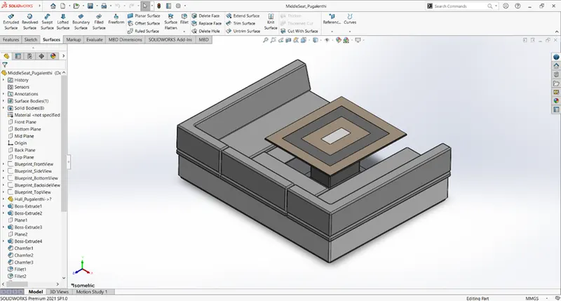
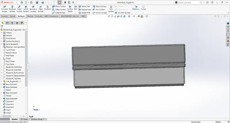
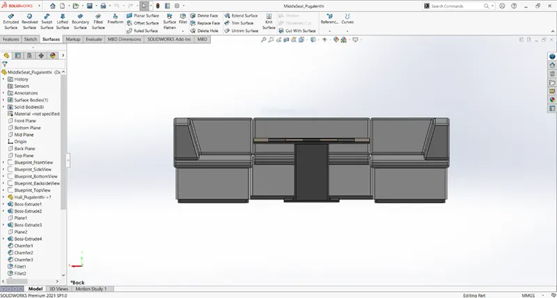
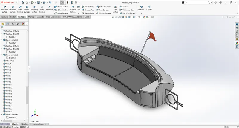
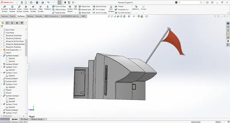
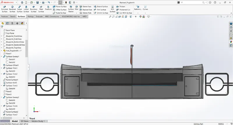
The different views of the front, middle and rear seats are shown below.
- Front Seat:
The structure of the front seat is first created using surfaces and then they are converted using solids, then mirrored along the midplane.
The front seat structure is considered from the blueprint.
The face of the seats was applied with the dome function. The seats are not merged as the single body.
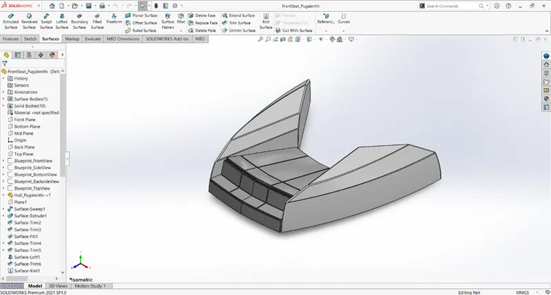
Middle Seat:
- Rear Seat:
Similarly, the rear seat is constructed as a front seat from surfaces, converted to solid in the final knit, and mirrored along the midplane.
Design of Super Structure:
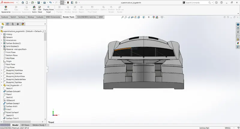
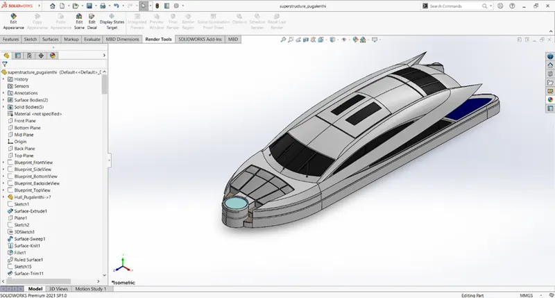
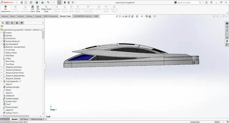
The front, right and isometric views of the superstructure are shown below.
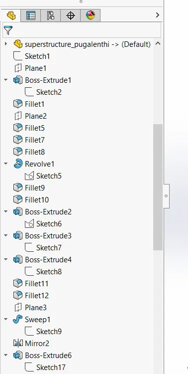
The superstructure is completely made of surfaces, knitted together, and converted into solid. The superstructure uses mainly the projected curves, surfaces lofts, extrudes, and trims to get the below structure and mirrored along the midplane. Applying necessary appearances to the model will result in the below structure.
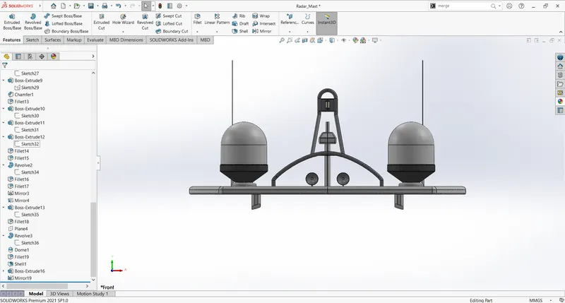
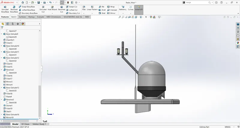
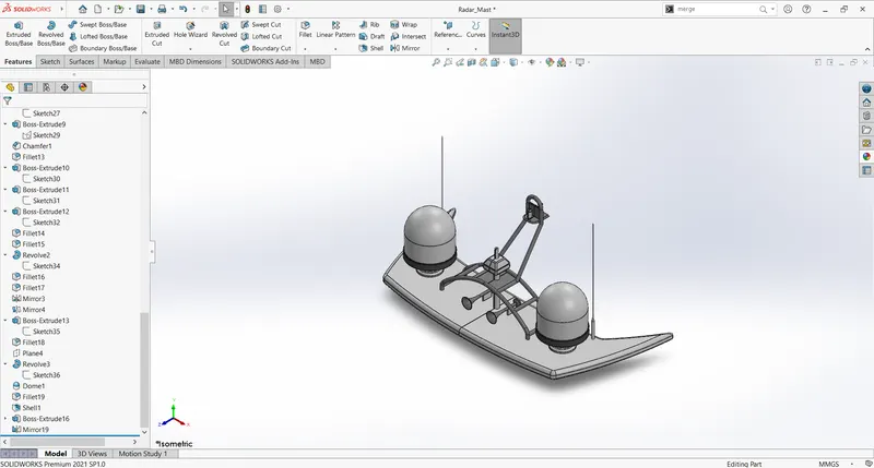
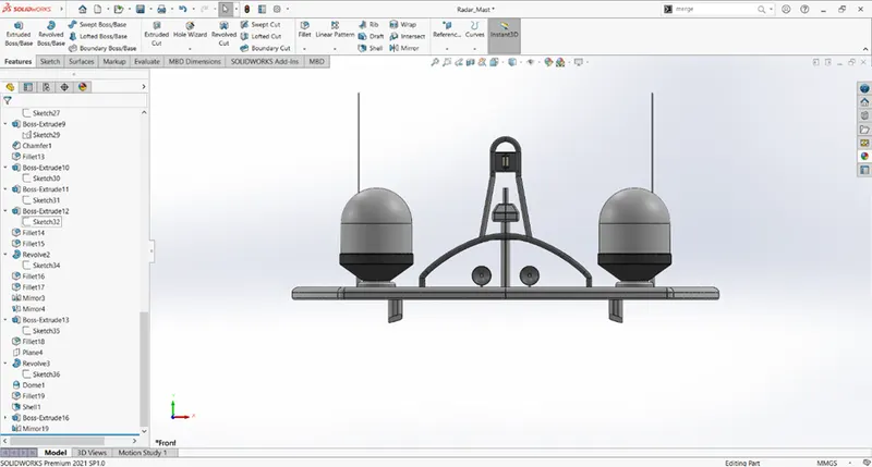
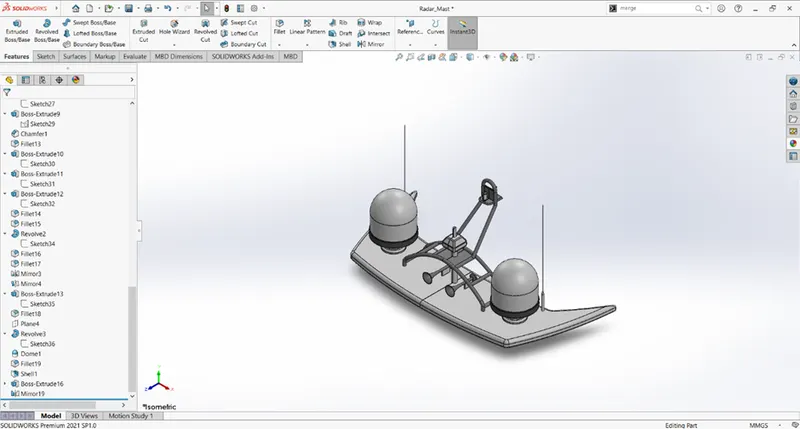
Design of Radar Mast:
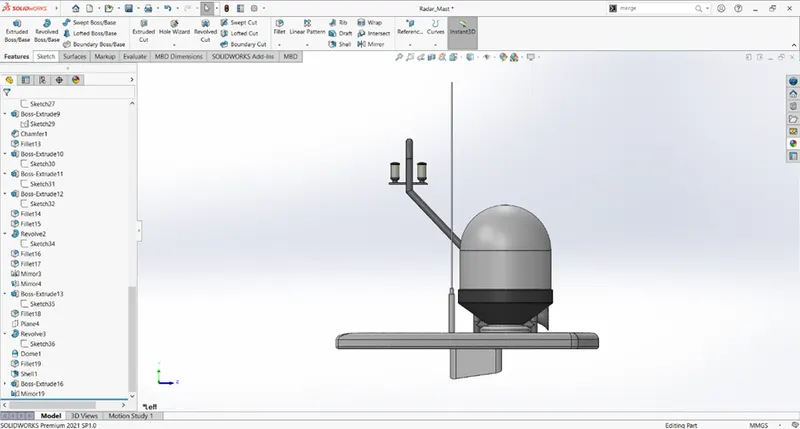
The front, right and isometric views of the superstructure are shown below.
The radar mast mainly uses, boss extrudes, revolved boss, swept boss to get the below structure.
Assembly of the yacht:
First, the hull is brought into an assembly environment with all main planes are made to coincide. And they are fixed.
Then, other parts i.e., front, rear, and middle seats, superstructure, radar mast are assembled by their front, top, and midplanes coincide with the same planes of the hull.
Then, the propellor is assembled with a concentric mate and end faces are made to coincide. enable lock rotation in the concentric mate. Repeat the same for all three mates.
Similarly for radar use the same set of mates in the radar mast part to assemble it.
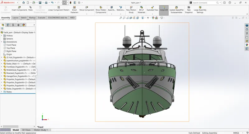
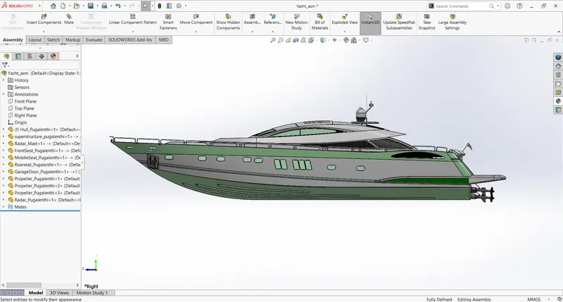
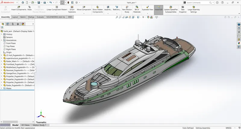
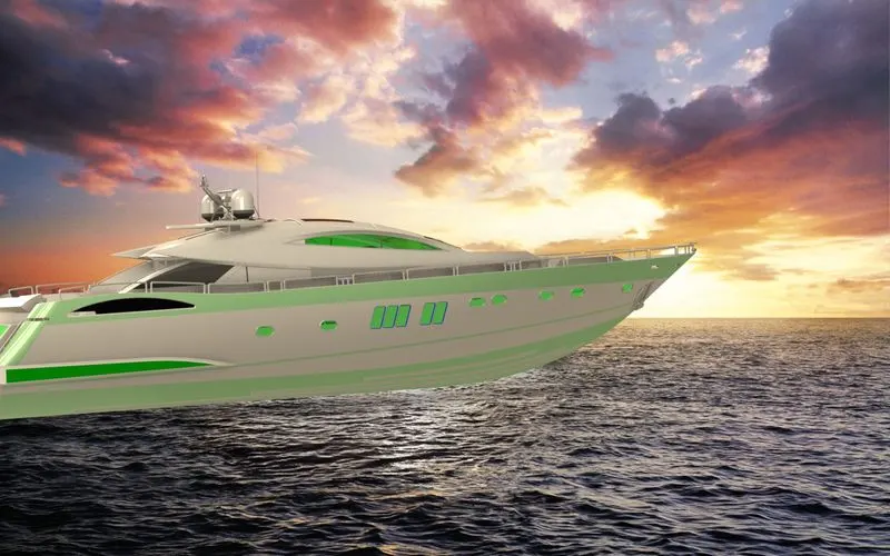
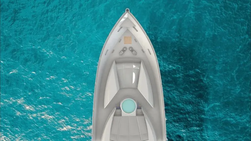
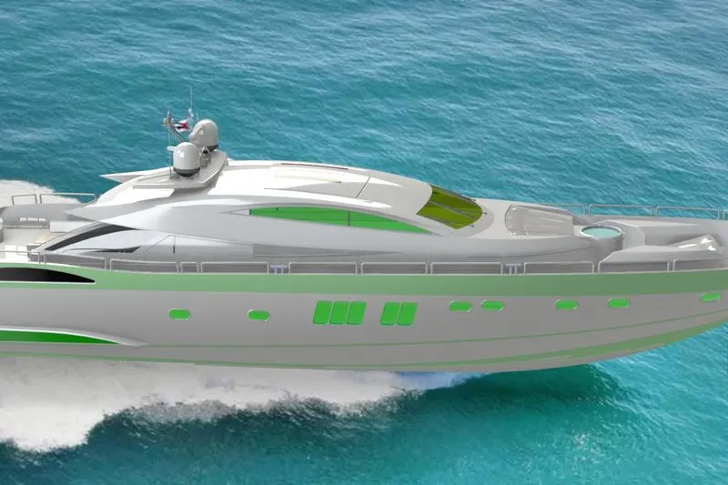
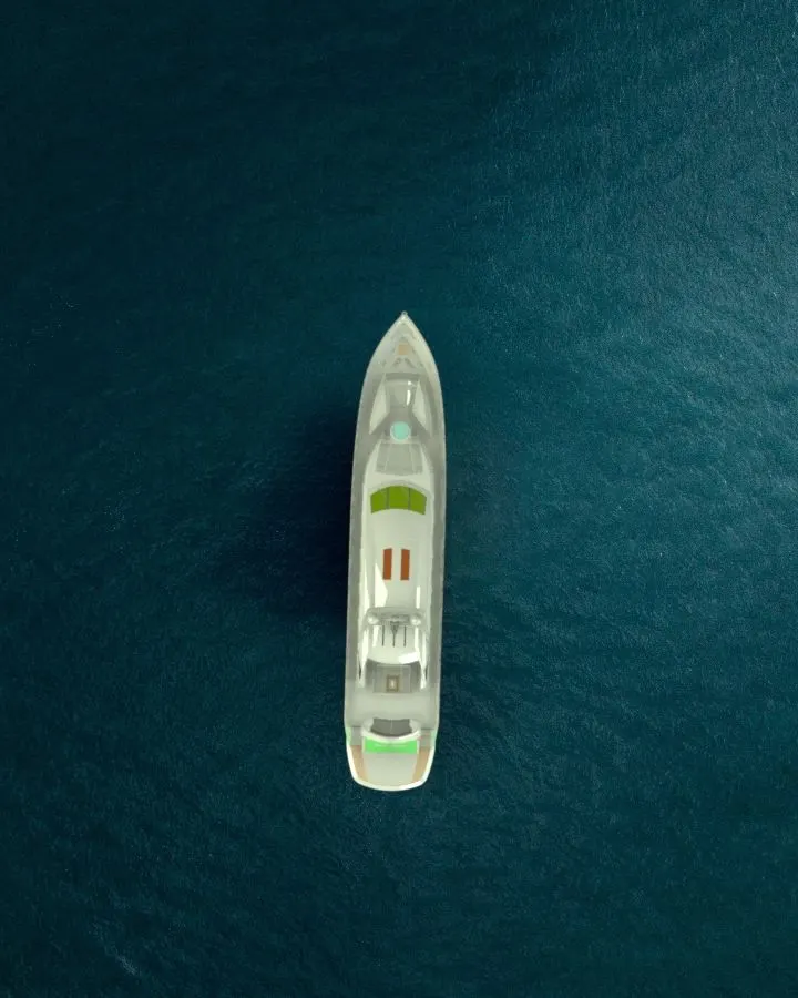
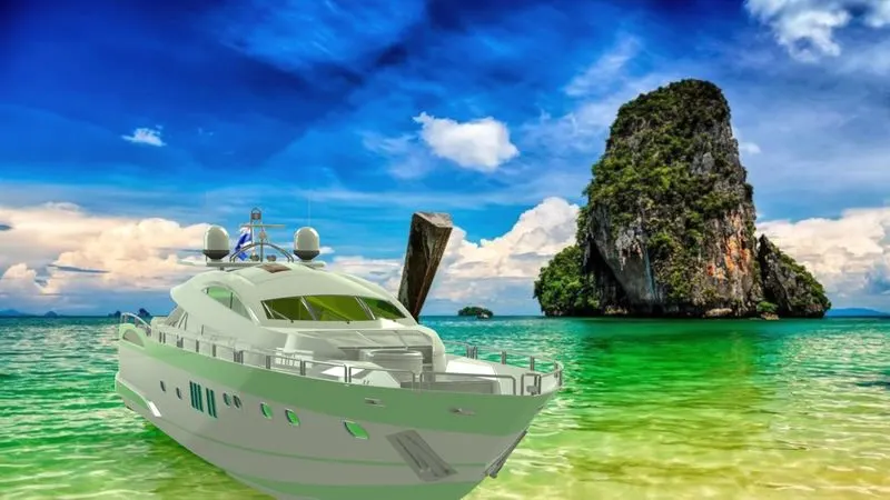
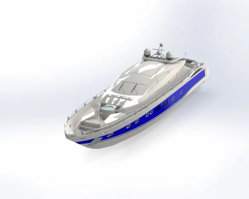
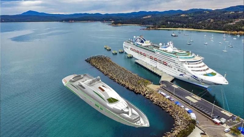
Photo – Realistic Rendering of the yacht using Solidworks visualize:
Conclusion:
The parts of the yacht are designed using solid and surface modeling, they are added with suitable appearances, rendered in Solidworks visualize.
By working on this project of creating a cosmetic model of the yacht, I get to familiarize myself with solid and surface modeling, assembling, and rendering using Solidworks