Week 7:- Base Unit Design Challenges 1
1. What is the Base Unit? What are the typical parts of the Base Unit?
- All of the tool's other units, such as the clamp, pin, rest, and other units, are mounted to the base unit.
- Additionally, additional tool components such as a pneumatic valve box and a trunking cable path will be installed on a base unit.
Fundamentals of the Base Unit
- The size of the base plate should encompass all of the units, including the opening on the outside.
- It is preferable to design a base plate using BCS coordinates.
- Drilling datum or measurement holes in a base plate should generally follow a 1000mm pitch.
- The size of the base plate determines how many datum holes are needed.
- Drilling datum holes should be done at nominal coordinate values and generally in terms of 50 and 100.
- Drilling datum holes should be done 100 mm from the outer units.
- Cover plates should be used to cover the datum holes.
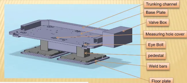
Parts of the Base Unit
Trunking Channel
A trunking channel is a conduit that holds all of the electrical and pneumatic wires and hoses for the tool's units.
Base Plate
A base plate is a machined steel and aluminum plate that is 25 to 40 mm thick. Holes are bored into it to install various components, such as a tool's clamp and pin units.
Valve Box
A valve box is a common component that houses all of the pneumatic units' valves. In essence, a valve box is a box that provides air to every other pneumatic cylinder. Since it is a device that has numerous other solenoid valves, it will have an inlet and an outlet, to which all other solenoid valves will be connected. Additionally, each solenoid valve will receive its input, which will then be provided to a different cylinder once again. The output will then be collected and returned to the valve box.
Eye Bolt
Eye bolts are utilized to move the tool with lift hooks, and in certain situations, fork lift holes will also be included for transportation. The entire unit will be dragged and moved. By putting hooks into them, eye bolts are utilized to raise the fixture for transportation. For instance, we frequently utilize M20 bolts, which are fastened to the base plate for transporting purposes. Occasionally, forklift holes are also included.
Pedestal
A pedestal is the component that joins the floor plate and base plate. In most cases, a pedestal is a standard component; but, in certain instances, it may be a welded frame that is incorporated with the base plate. The height and dimensions of a typical pedestal might vary. Depending on the base plate's dimensions, there are different numbers of pedestals for load distribution. Different types of pedestals have varying slopes.
Weld Bars
The positions are fixed in place with the help of weld bars. Steel plates that run along the sides of a pedestal's base plate are called weld bars.
Floor Plate
With a fixed bolt on the ground, the floor plate is grouted to the floor. Another name for floor plates is foundation plates. Ten millimeters will be kept between the floor plate and the pedestal base.
2. What are the points need to account while designing a Base Unit?
The type of welding fixture robotic or manual determines this. The working height of 850–1100 mm must be considered for manual fixtures; the norm for a given country will be applied based on the worker's height (human height is greater or lower in a few countries, such as the US and Japan). We can reach heights of 100 mm to around 250 mm if the base structure is constructed with a base plate that has tubular structure welded underneath it. In this instance, we must build more leg structure possibly with the top and plate welded to the tube in order to achieve the working welding height.
Knowing how large base plates or larger base welded structures will be handled during the manufacturing and handling process is crucial for designers. If the base size is very long, extra attention must be paid to flatness. Eyebolt sizes are used for lifting holes on the base plate based on weight. Usually, provisions are made for four-eye bolts.
Additionally, you must choose the eye bolt location so that no surrounding units (such as rest, clamp, or location units) are harmed by the ropes or belts used to move the structure or entire fixture. Just Welded framework and base plate You can determine whether you require a manufactured foundation or only a plate based on the component size and weight of the entire unit.
The plate is typically used with constructed bases composed of square or rectangular tubes. The majority of OEMs create four dowel holes at each corner and label the X, Y, and Z coordinates of the dowel holes with a little aluminum plate. A small number of OEMs use the technique of placing dowel holes 500mm apart if the base length is excessively long. For the fixture to deflect as little as possible, the base unit needs to be sufficiently sturdy.
The clamping of the workpiece and welding forces are what create this fixture's deflection. The fixture's base unit needs to be heavy enough to stop chatter and vibration. The base unit can be constructed from straightforward parts, allowing subsequent components to be welded or screwed together as needed. Welding is an option for the fixture's components that are permanently attached. The screws may be used to hold parts that require frequent replacement.
All of the units, including the aperture, should be covered by the base unit's outside perimeter. The base unit should be parallel to the floor; a height-adjusting mechanism should be available to change this.
3. What is a Dump Unit?
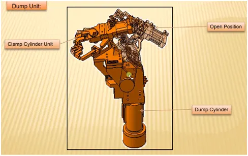
Occasionally, there are panels that are difficult to reach and cannot be fixed by basic units; in these situations, a dump unit is used to fix them. For this purpose, a dump unit may have many cylinders. The assembly containing clamp mylars and pins is dumped by the first cylinder, and it then carries out the necessary function. In this unit, we should ensure that the panel can be removed when it is in its open position.
Fundamentals
- To limit the motion of the panel being welded and to guarantee that it rests properly.
- Must make sure the panel doesn't rotate and to secure it using magnets, side blocks, or pins.
- Must guarantee that the cylinder has adequate clamping force to prevent movement during welding.
- For the panel to be adjusted, the dump unit should have the proper shimming.
- A clamp cylinder or a slide cylinder can be fitted to a dump unit.
- In the case of a dump unit, cylinder validation is crucial because the weight may be too great for the cylinder to dump.
- Calculations are made in this situation, and the force that the cylinder exerts is compared to the weight of the load that it is carrying.
4. What are the points you need to consider while designing a Dump unit?
The dump unit is a multi-part, intricate unit. Therefore, we must exercise additional caution when developing a dump unit because any design error could lead to irrevocable mistakes that could waste money and effort. Therefore, we need make sure that everything is taken care of so that we don't run into issues later.
Points need to be considered
3-2-1 principle
After we have added a clamping cylinder and designed the remaining mylars, pins, and clamps. We shall inspect the clamping and resting position of the welded panel. The assembly will be deposited onto the panel in order to function. It is significant since it is the rationale behind the development of a dump unit. The most crucial factor is the panel's spatial precision.
Mass
It is important to ensure that the assembly being disposed of weighs as little as feasible without sacrificing its strength. This is due to the fact that the force needed to push and pull the assembly will decrease with decreasing weight. Here, we use steel for the remaining components and aluminum for the cylinder in order to determine the mass of the moving assembly. For the factor of safety, we take a little bit more mass than is estimated.
Time of opening and closing
Additionally, we must remember that the clamp should open and close as quickly as feasible; this will rely on the cylinder's power and the weight of the assembly being emptied. We must limit it to a minimum because if it takes, say, two seconds to open, we won't be able to empty the panel during that time, increasing the cycle time and increasing idle time.
Cylinder validation
Because the cylinder must be able to push the load during operation and then pull it back after the action is finished, cylinder validation is a crucial component of the design of any clamp unit or dump unit. The following computations are required for this.
Calculating the center of gravity of moving assembly
Determining "the longest perpendicular distance from a vertical line that passes through the C.G and pivot center." Either the work position, the rest position, or any combination of these could have the longest perpendicular distance. Finding "the shortest distance between pivot center and cylinder line." All of these values are added to the table along with the cylinder bore, and the results indicate whether or not the cylinder is validated using the push and pull force formula included in the table. The cylinder is validated if the computed force exceeds the necessary force; if not, a new cylinder is used.
Open position
Because the panel shouldn't fly with the unit during removal, we must further verify the open status following the cylinder validation.
5. What is a Slide unit?
A slide the unit may be equipped with a clamp, pin, or rest unit that slides forward, completes the necessary function, and then slides backward. It features a cylinder that pulls and pushes the unit forward. Sensor units, stoppers, guide blocks, locking units, slide cylinders, and other components are included in the slide unit. To sense the position, there are sensor units at the very extremities of the sliding unit. The slide should not be opened or closed. Sliding units are essentially utilized in situations when space or other limitations make it impossible to construct the entire assembly using several unit types. Thus, you will just utilize this slide here. The sliding cylinder, which has two positions—open and closed—must control the rails as the entire panel moves. The entire plate cannot move because of the position locking unit, which locks the position at that specific moment. Sensors must detect whether or not the full component has arrived here.
As I mentioned before, stopper blocks are a movable component that regulates the movement of the entire panel. In locations with limited space and limited accessibility, slide units are utilized. Because each panel needs a resting place using clamping and sensing, there are occasionally too few panels close to one another and not enough room. When the panel is angled, this becomes more challenging. The solution to this issue is to use guide rails, guide locks, a cylinder, locking mechanisms, stoppers, sensors, and a slide unit to install rests, clamps, or pins on a slide, or all of them. This slide device goes forward when the panel is ready to be welded, unloads the panel, positions the panel in a certain location, or finishes its operation before sliding backward. The remaining panels are then fastened in place in a similar manner.
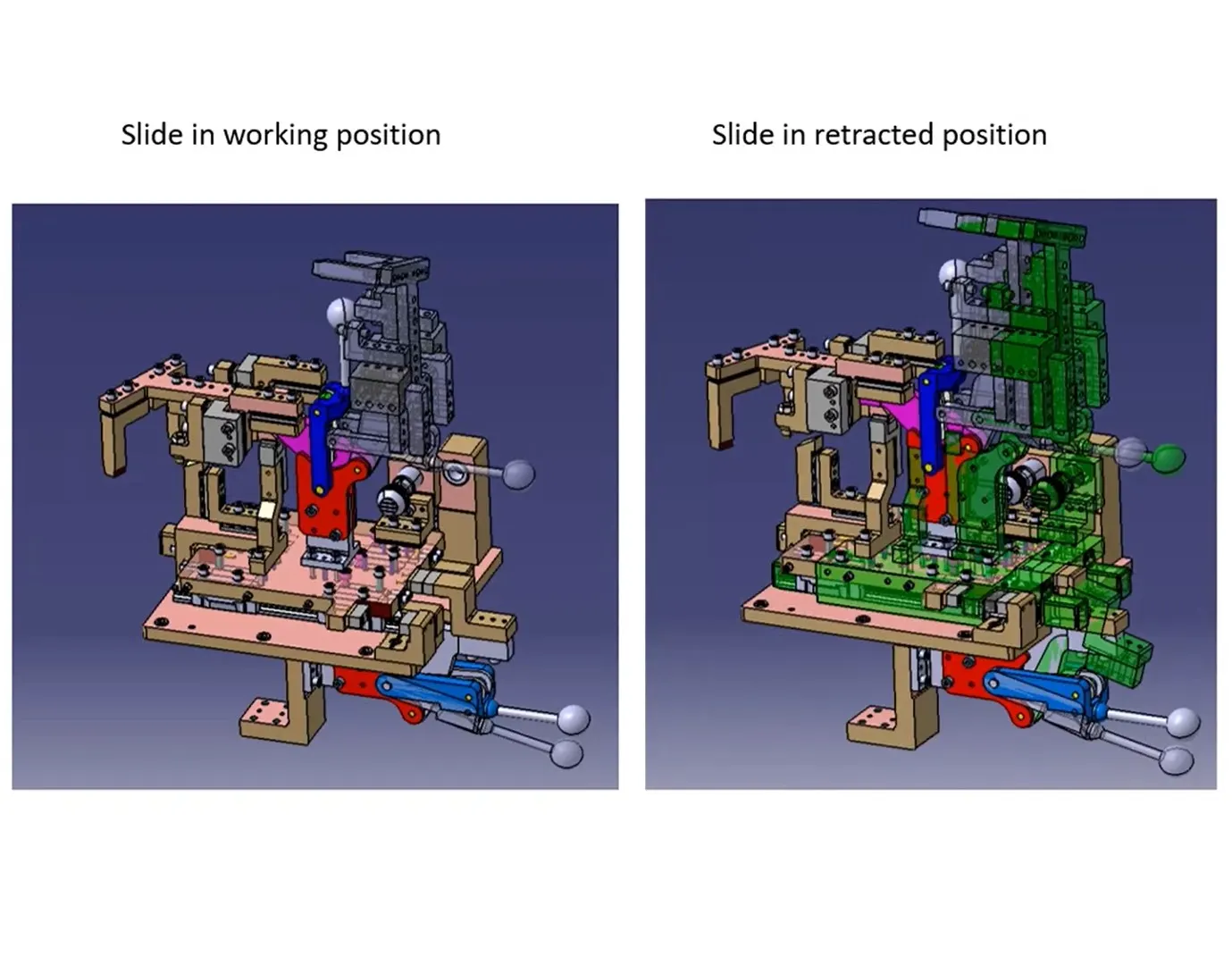
Slide units can be classified into two types on the base of the type of guide-ways used
- Hardened guide ways
- LM guide way
Slide units can be classified into three types on the base of the prime mover used
- Manual slides
- Hydraulic/pneumatic slides
- CNC slides
It may also be classified depending on application
- Horizontal slide
- Vertical slide
- Angular slide
6. What are the points you need to consider while designing a Slide unit?
Weight carrying capacity
The market offers a variety of guide rail types, each with a distinct load capability. As a result, we determine the weight of our assembly and the rail's weight capacity. As a result, we select rail according to its capacity to carry loads.
Push and Pull force
Particularly when the slide is inclined, we must determine whether the push and pull forces are sufficient to push and pull the slide.
Locking mechanism
When the slide is in the open or retractable position, the locking mechanism makes sure it stays in place. The panel may sustain damage if the slide moves during the welding process since it will impair positional precision.
Stopper Block
To stop the slide at the desired place, stopper blocks are utilized. It is crucial because, in order for the sliding unit to rest and locate properly, any rest mylars and pins must be stopped in their designated positions. It could dent the panel if there is no stopper.
Sensor Unit
A sensor unit aids in determining the slide's position. The operator presses the button to begin the procedure, and the slide advances. The PLC executes the following action after receiving this signal from the sensor indicating the unit's presence.
Stroke
Depending on the work area we wish to clear, we must choose the stroke length.
Open position
Since the slides are the only moving elements, we must inspect the fowling with a rifle or other nearby device. We cannot approve the design until this has been verified.