Week 7-12-Creation of 1D Connectors Challenge
AIM: The main aim of this challenge is to mesh the given frame assembly and deploy the connections as per given criteria.
Element Quality Criteria:
|
S.no |
Element Quality Criteria |
Value |
|
1 |
Target/Average length |
5 |
|
2 |
Minimum Length |
2 |
|
3 |
Maximum Length |
8 |
|
4 |
Aspect |
5 |
|
5 |
Warpage |
15 |
|
6 |
Skewness |
45 |
|
7 |
Taper |
0.5 |
|
8 |
Minimum Quad Angle |
45 |
|
9 |
Maximum Quad Angle |
135 |
|
10 |
Minimum Tria Angle |
30 |
|
11 |
Maximum Tria Angle |
110 |
|
12 |
Tria Percentage |
15 |
Connection Criteria:
1. Right_Rail_2 & Front_truss_1: - Seam-Quad(angled+capped+L)
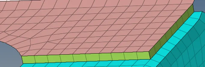
2. Left_Rail_2 & Front_truss_1: - Quad elements
3. Front_truss_2, Front_truss_1 & Right_Rail_1: - Spot weld with 2 Layers and 5 mm Diameter
4. Front_truss_2, Front_truss_1 & Left_Rail_1: - Hexa (Adhesive)
5. Rear_truss_2 & Right_Rail_2: - Bolt Connector
6. Rear_truss_2 & Left_Rail_2: - Bolt Connector
7. Right_Rail_1 & Right_Rail_2: - Spot-weld with Rigid Elements
8. Left_Rail_1 & Left_Rail_2: - Spot-weld with Spring Elements.
OBJECTIVE: The objectives of this challenge are as follows:
1. To perform geometry cleanup for the given mid surface model.
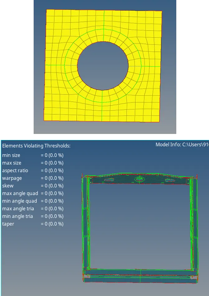
2. To mesh the given component as per given quality criteria and maintain a proper mesh flow.
3. Deploying different types of connections where ever it is required as per given criteria.
P ROCEDURE:
Meshing the components
The CAD file in Hypermesh can be opened by selecting import model option.
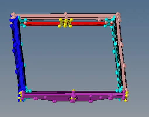
1. After opening the file, manual cleanup was performed to remove free edges and non-manifold edges.
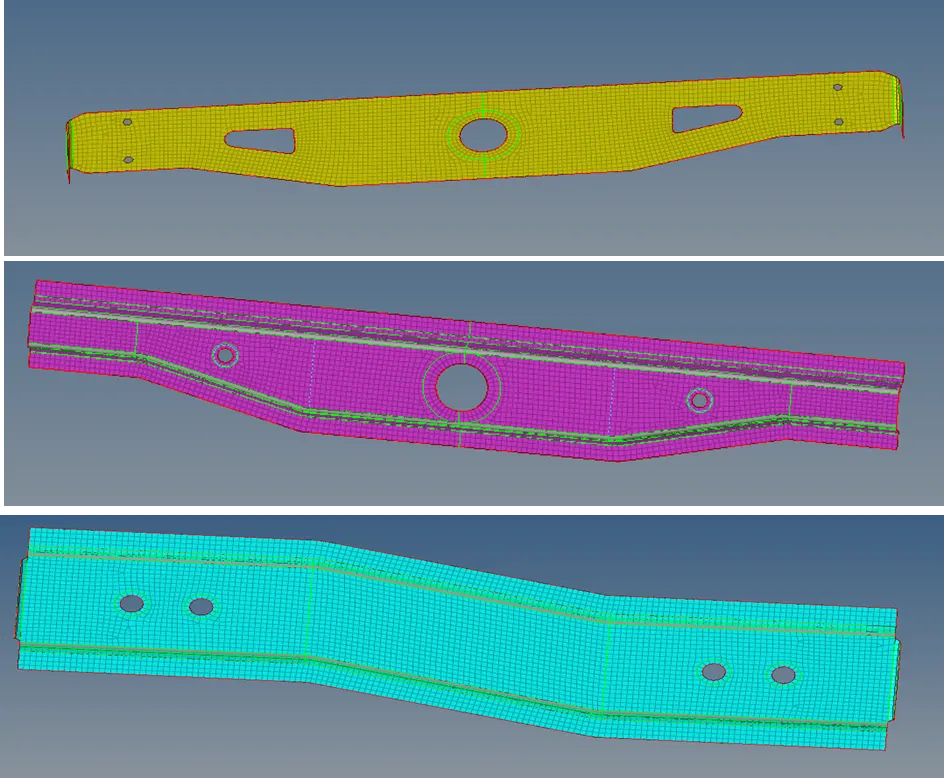
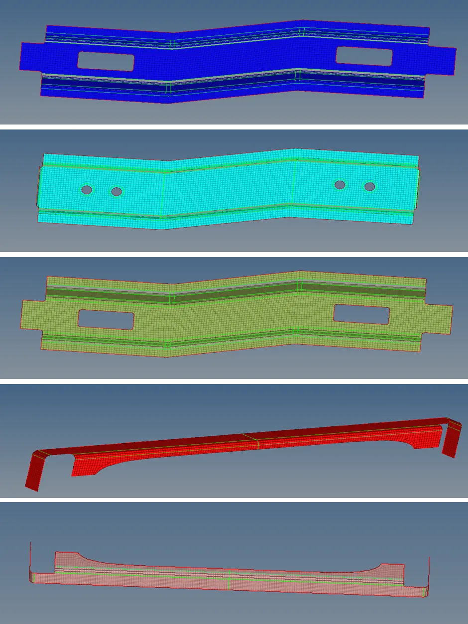
2. Totally there were 9 components in the given model and each component was meshed(2DàAUTOMESH) separately as per given quality criteria.
For symmetrical components, only half the components were meshed initially and reflect (TOOLSàREFLECTàELEMENTS) option was used for deploying the mesh on the other half of the component.
Connections:
Right_Rail_2 & Front_truss_1: - Seam-Quad(angled+capped+L)
· Initially, the two components Right Rail-2 & Front Truss-1 were isolated from the rest of the components.
· For deploying the seam connections (1DàCONNECTORSàSEAM) we must go to connectors sub panel.
· Location, components to be connected, weld angle, spacing, tolerance & type of weld to be deployed were given as inputs.
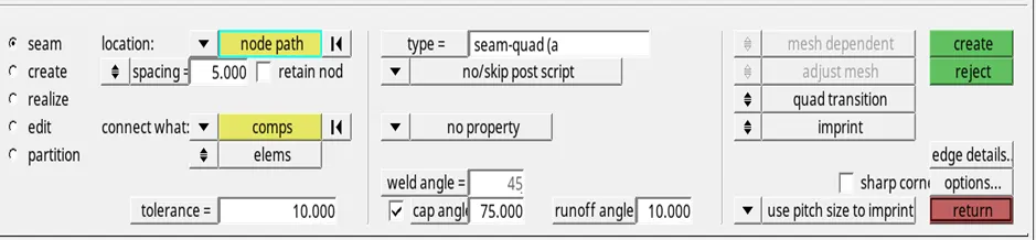
· The final connection is shown in the below image.

Left_Rail_2 & Front_truss_1: - Quad elements
· Initially, the two components Left Rail-2 & Front Truss-1 were isolated from the rest of the components.
· For deploying the seam connections (1DàCONNECTORSàSEAM) we must go to connectors sub panel.
· Location, components to be connected, spacing, tolerance & type of weld to be deployed were given as inputs.
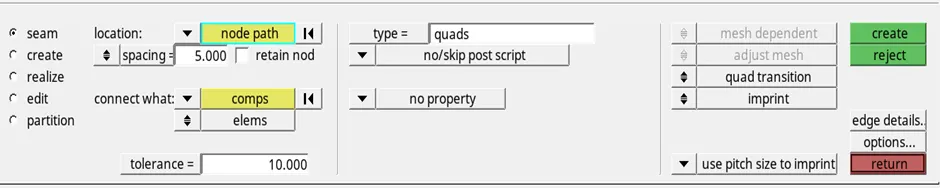
· The final connection is shown in the below image.
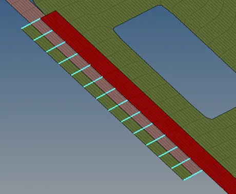
Front_truss_2, Front_truss_1 & Right_Rail_1: - Spot weld with 2 Layers and 5mm Diameter
· Initially, the three components Front Truss-2, Front Truss-1&Right Rail-1 were isolated from the rest of the components.
· For deploying the spot connection (1DàCONNECTORSàSPOT) we must go to connectors sub panel.
· Location, components to be connected, spacing, tolerance, number of layers, Dia of weld & type of weld to be deployed were given as inputs.

· The final connection is shown in the below image.
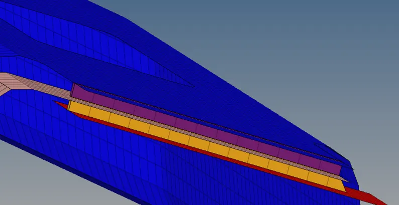
Front_truss_2, Front_truss_1 & Left_Rail_1: - Hexa (Adhesive)
· Initially, the three components Front Truss-2, Front Truss-1&Left Rail-1 were isolated from the rest of the components.
· For deploying the adhesive connections (1DàCONNECTORSàSEAM) we must go to connectors sub panel.
· Location, components to be connected, strips, coats, spacing, tolerance & type of weld to be deployed were given as inputs.
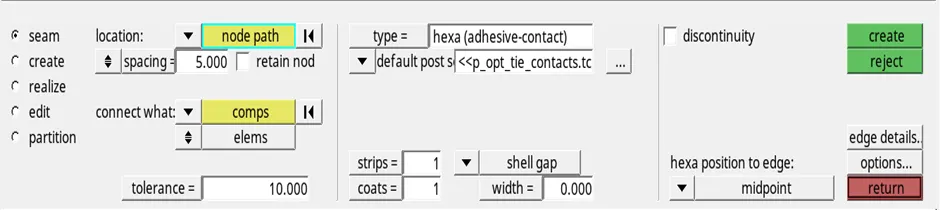
· The final connection is shown in the below image.
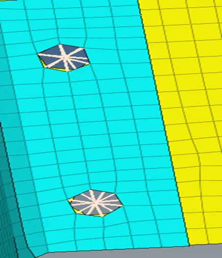
Rear_truss_2 & Right_Rail_2: - Bolt Connector
· Initially, the two components Right Rail-2 & Rear Truss-2 were isolated from the rest of the components.
· For deploying the bolt connections (1DàCONNECTORSàBOLT) we must go to connectors sub panel.
· Location, components to be connected, number of layers, tolerance & type of bolt to be deployed were given as inputs.
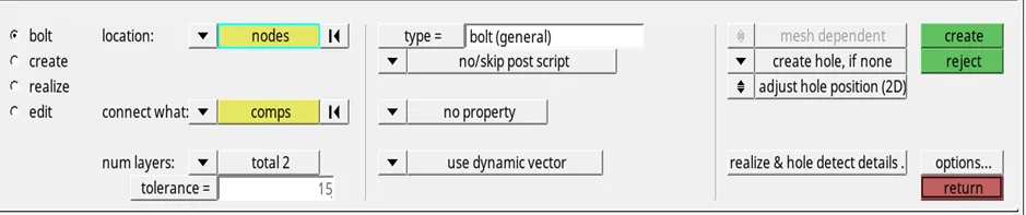
· The final connection is shown in the below image.
Rear_truss_2 & Left_Rail_2: - Bolt Connector
· Initially, the two components Left Rail-2 & Rear Truss-2 were isolated from the rest of the components.
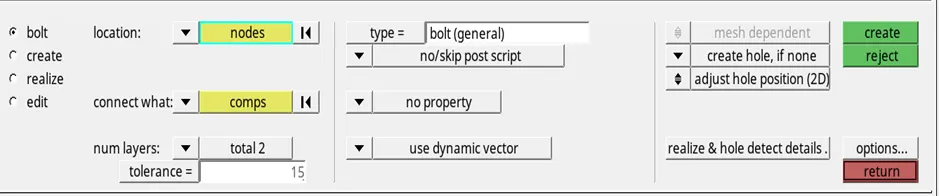
· For deploying the bolt connections (1DàCONNECTORSàBOLT) we must go to connectors sub panel.
· Location, components to be connected, number of layers, tolerance & type of bolt to be deployed were given as inputs.
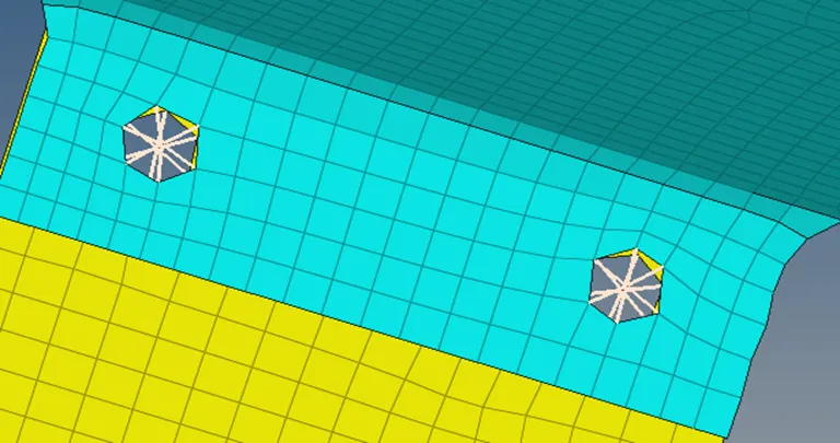
· The final connection is shown in the below image.
Right_Rail_1 & Right_Rail_2: - Spot-weld with Rigid Elements
· Initially, the two components Right Rail-2&Right Rail-1 were isolated from the rest of the components.
· For deploying the spot connection (1DàCONNECTORSàSPOT) we must go to connectors sub panel.
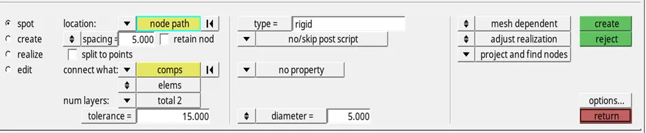
· Location, components to be connected, spacing, tolerance, number of layers, Dia of weld & type of weld to be deployed were given as inputs.
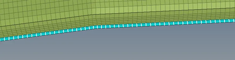
· The final connection is shown in the below image.
Left_Rail_1 & Left_Rail_2: - Spot-weld with Spring Elements.
· Initially, the two components Left Rail-2&Left Rail-1 were isolated from the rest of the components.
· For deploying the spot connection (1DàCONNECTORSàSPOT) we must go to connectors sub panel.
· Location, components to be connected, spacing, tolerance, number of layers, Dia of weld & type of weld to be deployed were given as inputs.

· The final connection is shown in the below image.
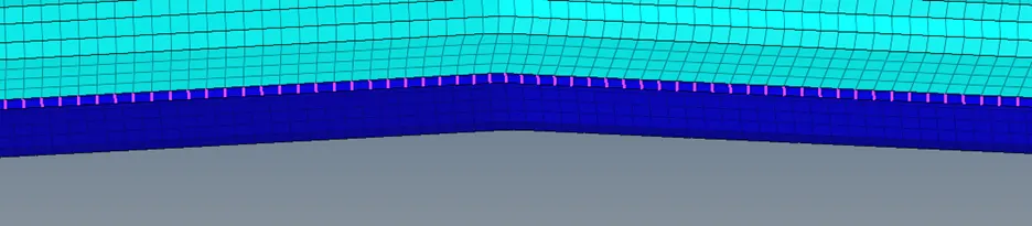
Other Connections
· For deploying the other suitable connections, we should know the components that were not connected to their adjacent components.
· For finding the components that were not connected to their adjacent components Mask (TOOLSàMASKàELEMENTSàBY ATTACHEDàMASK) option was used.
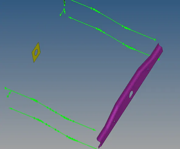
· We can see that reinforcement plate and Rear Truss-1 were not connected to any of their adjacent components.so, we need to connect these two components with suitable connections to their adjacent components.
Front_truss_2, Front_truss_1& Reinforcement plate: - Spot-ACM.
· Initially, the three components Front Truss-2, Front Truss-1&Reinforcement plate were isolated from the rest of the components.
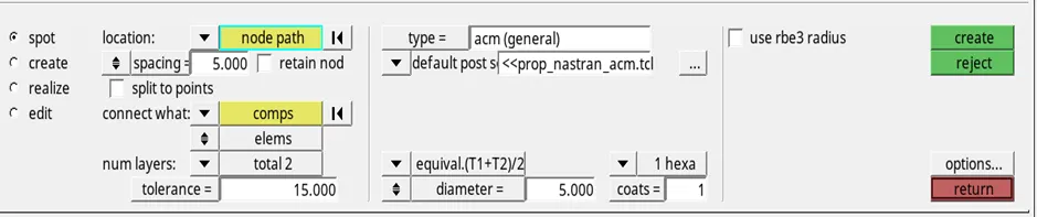
· For deploying the spot connection (1DàCONNECTORSàSPOT) we must go to connectors sub panel.
· Location, components to be connected, spacing, tolerance, number of layers, Dia of weld & type of weld to be deployed were given as inputs.
· The final connection is shown in the below image.
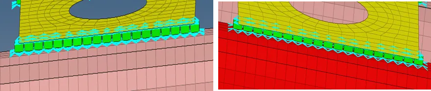
Rear Truss-1& Rear Truss-2: - ADHESIVES.
· Initially, the two components Rear Truss-1& Rear Truss -2 were isolated from the rest of the components.
· For deploying the adhesives connection (1DàCONNECTORSàAREA) we must go to connectors sub panel.
· Location, components to be connected, tolerance, & type of weld to be deployed were given as inputs.
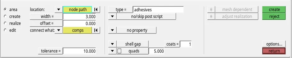
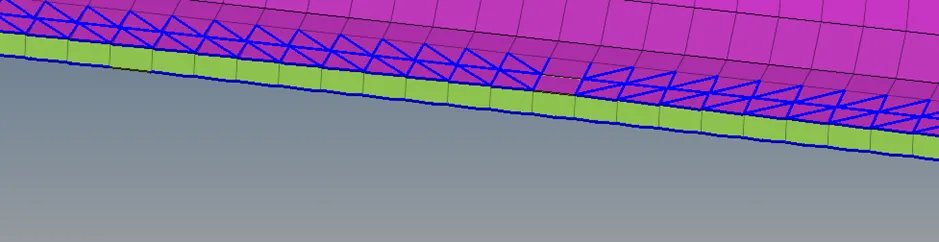
· The final connection is shown in the below image.
Connections Check:
· After deploying all the connections, we must use Mask (TOOLSà MASKà ELEMENTSà BY ATTACHEDàMASK) command to make sure that all the components were connected.
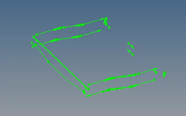
· From the above image after using Mask option, we can see no components were visible. Therefore, we can confirm that all the components in the assembly were connected properly.
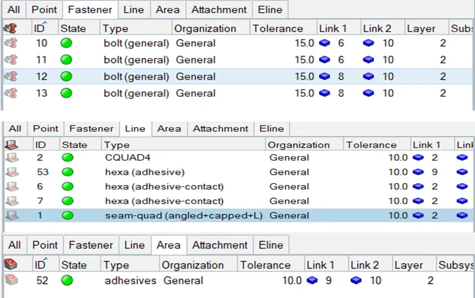
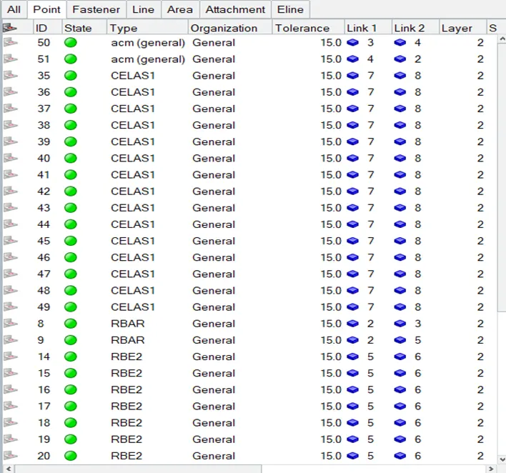
· To know whether all our deployed connections are realized or not, we need to go to connectors panel and check the state of the connector. If the state is in green colour then we can say all the connecters were realized.
RESULTS:
1. Successfully meshed the given assembly without any elemental failure and deployed the suitable connections as per desired requirement.