Week 7-12-Creation of 1D Connectors Challenge
Objective :
Mesh the given model with proper quality and connect the all components with suitable connectors
Procedure :
1) import the given model (geometry) in the hypermesh window
2) perform the geometry cleanup on the given model using quick edit panel
3) generating mesh on the given geometry with proper mesh flow
4)check the quality of the mesh in the check elements option in tool panel
5) go to the 3D panel and select the connectors option in that window
6) hide all the components other than the two components need for connection
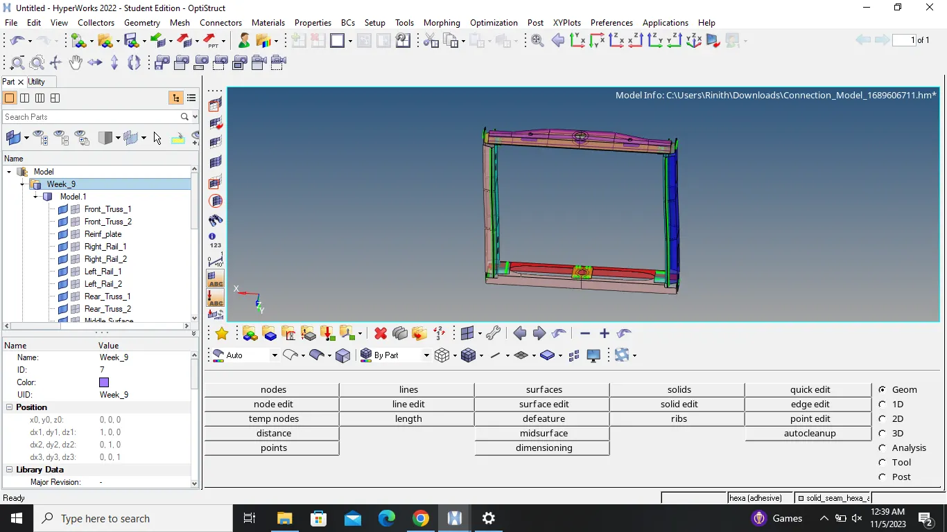
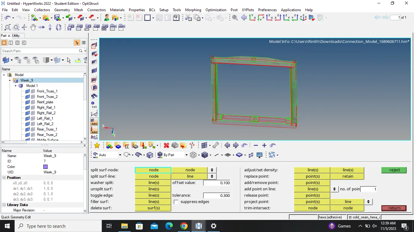
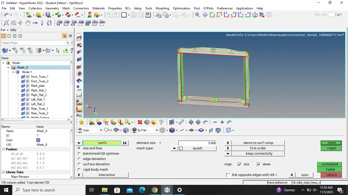
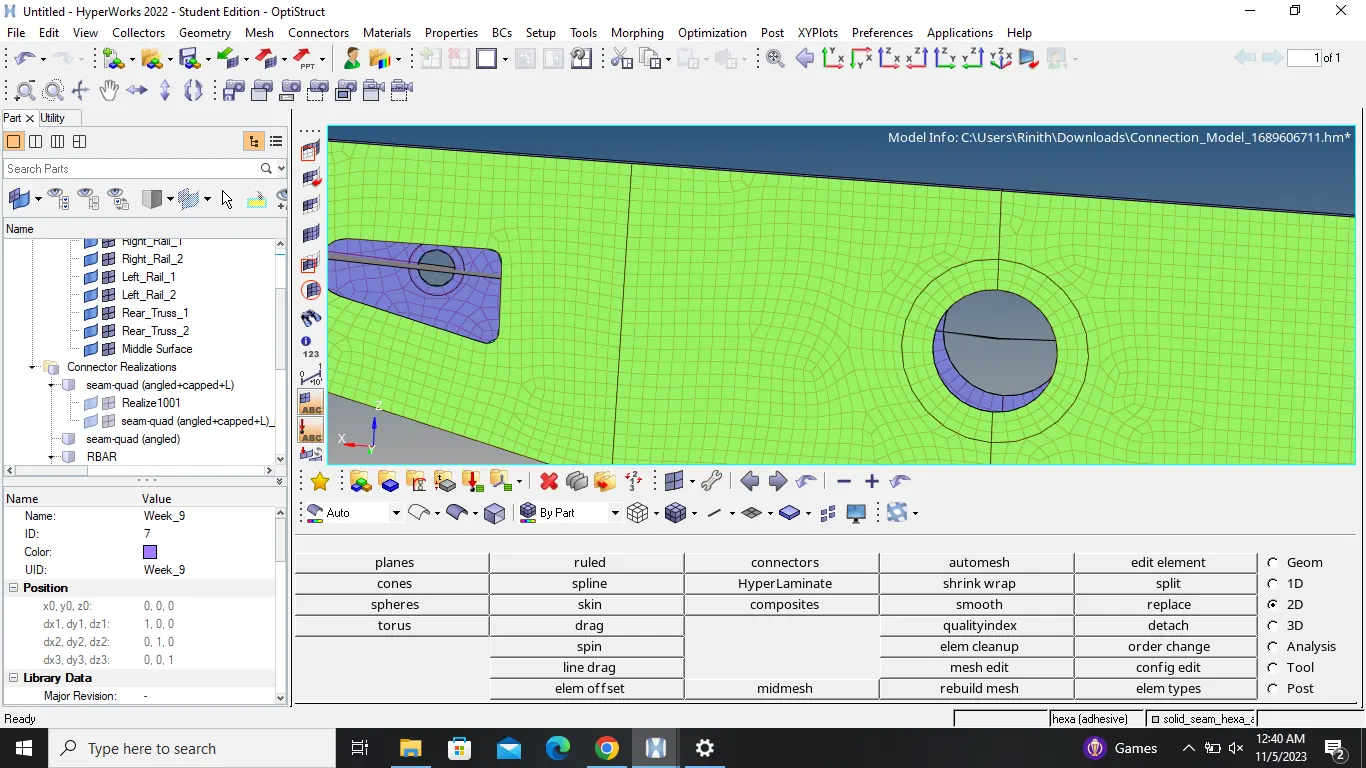
1. Right_Rail_2 & Front_truss_1:- Seam-Quad(angled+capped+L)
Other than the two.....hide all the components
Go to 3D and choose connectors
Select seam option
Inside the panel , select the quad type
Select the nodes and respective components
Give the tolerance angle
Assign the respective property
Finally create the connector
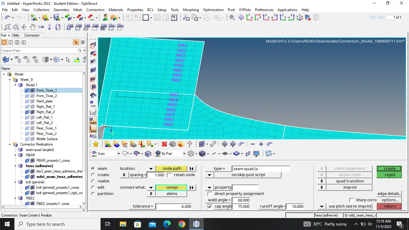
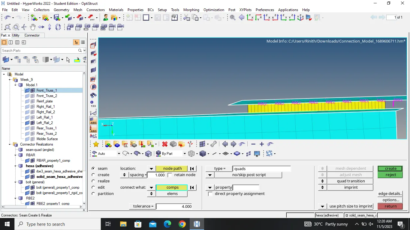
2. Left_Rail_2 & Front_truss_1:- Quad elements
Other than the two.....hide all the components
Go to 3D and choose connectors
Select seam option
Inside the panel , select the quad type
Select the nodes and respective components
Give the tolerance angle
Assign the respective property
Finally create the connector
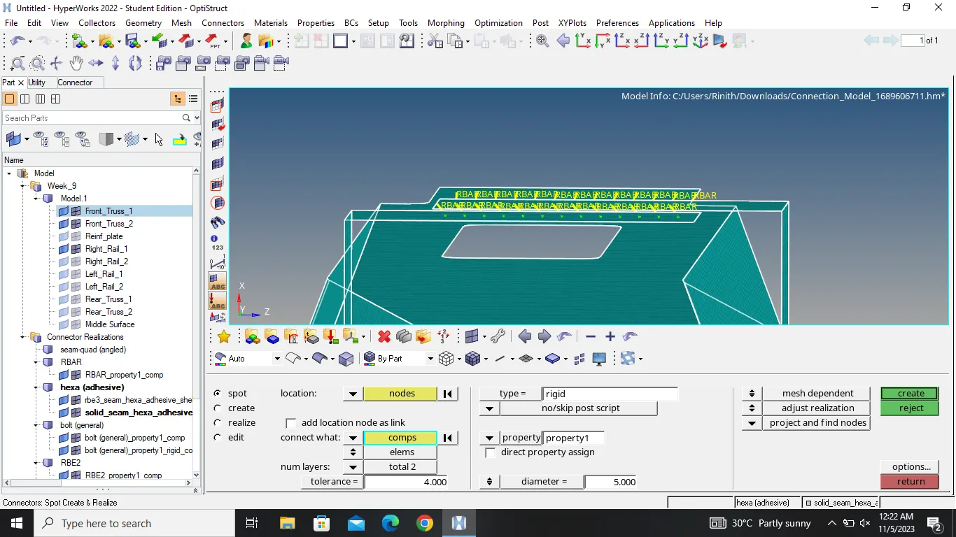
3. Front_truss_2, Front_truss_1 & Right_Rail_1:- Spot weld with 2 Layers and 5 mm Diameter
Other than the two.....hide all the components
Go to 3D and choose connectors
Select spot option
Inside the panel , select the weld type
Select the nodes and respective components
Give the tolerance angle
Assign the respective property
Assign the diameter and layers count
Finally create the connector
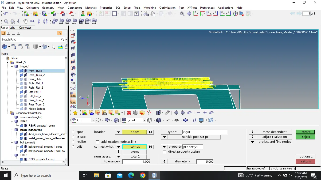
4. Front_truss_2, Front_truss_1 & Left_Rail_1:- Hexa (Adhesive)
Other than the two.....hide all the components
Go to 3D and choose connectors
Select seam option
Inside the panel , select the hexa(adhesive)type
Select the nodes and respective components
Give the tolerance angle
Assign the respective property
Finally create the connector
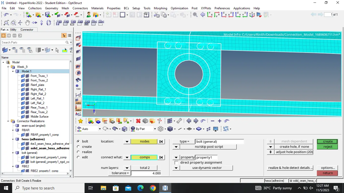
5. Rear_truss_2 & Right_Rail_2:- Bolt Connector
Other than the two.....hide all the components
Go to 3D and choose connectors
Select bolt option
Inside the panel , select the bolt type
Select the nodes and respective components
Give the tolerance angle
Assign the respective property
Finally create the bolt connector
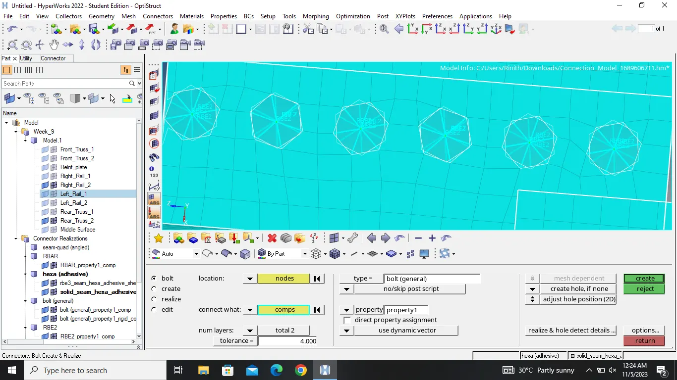
6. Rear_truss_2 & Left_Rail_2:- Bolt Connector
Other than the two.....hide all the components
Go to 3D and choose connectors
Select bolt option
Inside the panel , select the bolt type
Select the nodes and respective components
Give the tolerance angle
Assign the respective property
Finally create the bolt connector
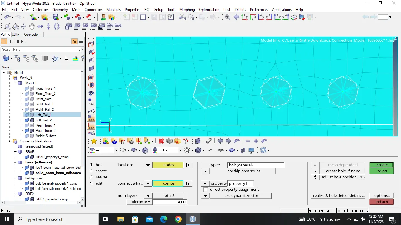
7. Right_Rail_1 & Right_Rail_2:- Spot-weld with Rigid Elements
Other than the two.....hide all the components
Go to 3D and choose connectors
Select spotweld option
Inside the panel , select the rigid type
Select the nodes and respective components
Give the tolerance angle
Assign the respective property
Finally create the connector
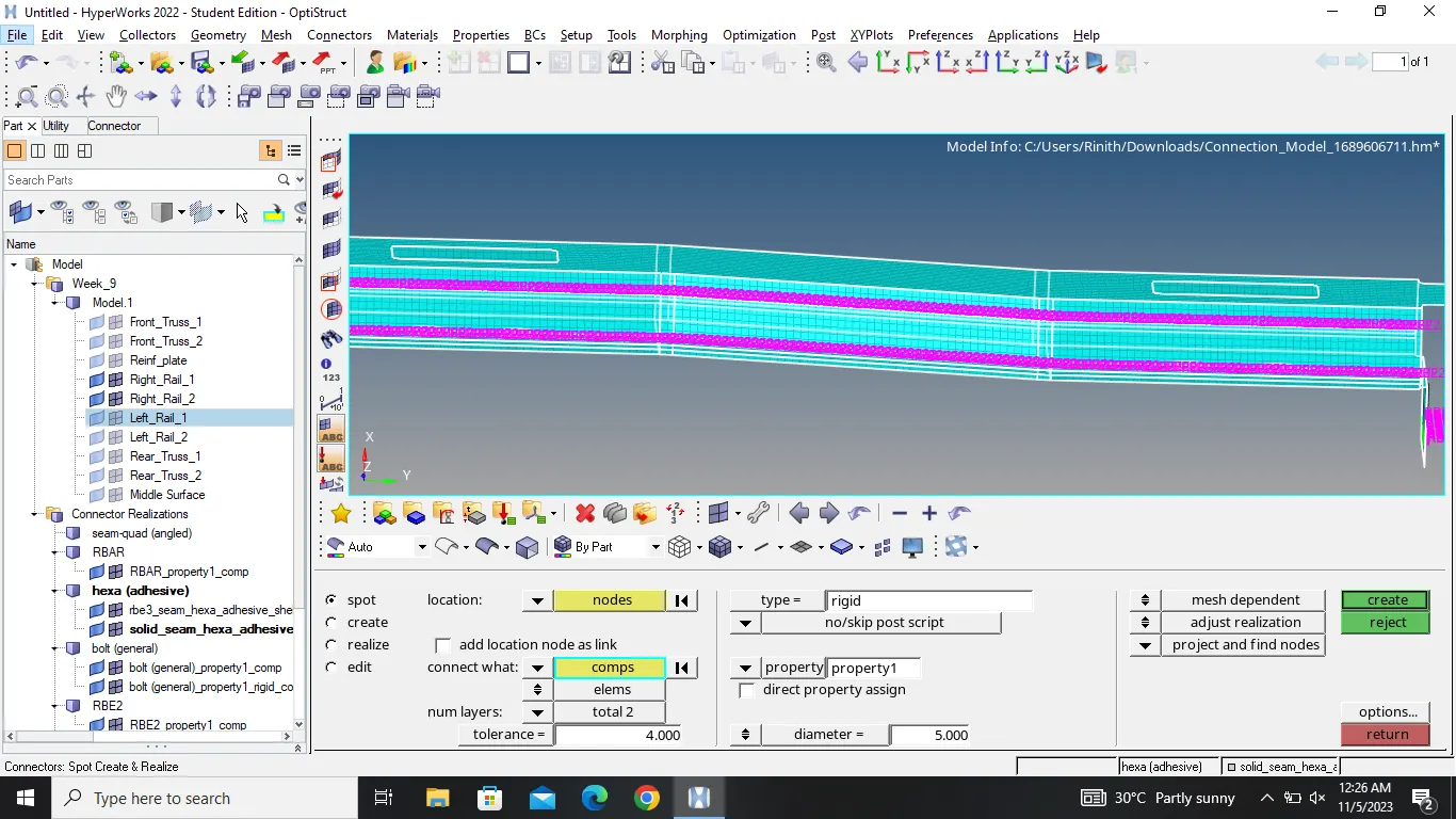
8. Left_Rail_1 & Left_Rail_2:- Spot-weld with Spring Elements
Other than the two.....hide all the components
Go to 3D and choose connectors
Select spot weld option
Inside the panel , select the spring type
Select the nodes and respective components
Give the tolerance angle
Assign the respective property
Finally create the connector
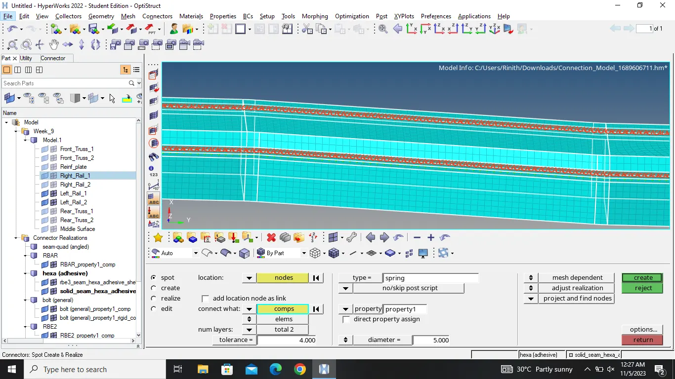
Other than this , all other components are connected with suitable connectors successfully
Conclusion :
The given model (geometry) is successfully meshed and components are connected with suitable connectors successfully.