Week 7-12-Creation of 1D Connectors Challenge
AIM: In this challenge, follow the below mentioned quality criteria and mesh the given geometry.
GIVEN:
S. No. Quality Criteria Value
1 Target/Average Length 5
2 Aspect Ratio 5
3 Skewness 45
4 Warpage 15
5 Taper 0.5
6 Minimum Length 2
7 Maximum Length 8
8 Minimum Quad Angle 45
9 Maximum Quad Angle 135
10 Minimum Tria Angle 30
11 Maximum Tria Angle 110
12 Tria Percentage 15
Create a connector and Attach the various parts of the given model
1. Right_Rail_2 & Front_truss_1:- Seam-Quad(angled+capped+L)
2. Left_Rail_2 & Front_truss_1:- Quad elements
3. Front_truss_2, Front_truss_1 & Right_Rail_1:- Spot weld with 2 Layers and 5 mm Diameter
4. Front_truss_2, Front_truss_1 & Left_Rail_1:- Hexa (Adhesive)
5. Rear_truss_2 & Right_Rail_2:- Bolt Connector
6. Rear_truss_2 & Left_Rail_2:- Bolt Connector
7. Right_Rail_1 & Right_Rail_2:- Spot-weld with Rigid Elements
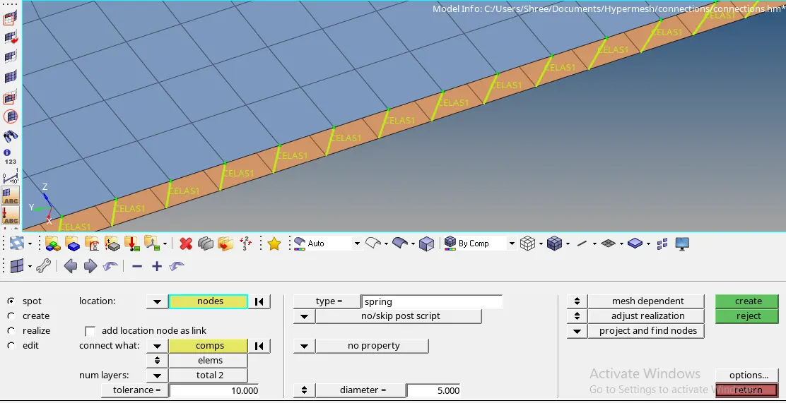
8. Left_Rail_1 & Left_Rail_2:- Spot-weld with Spring Elements
9. Rest all the components left Join them with suitable connectors
OBJECTIVE: The objective of this challenge is to mesh the model following the given Quality Criteria and attach various parts the given model by applying given connections.
PROCEDURE:
<!-- [if !supportLists]-->1. <!--[endif]-->Meshing the component:-
1. <!--[endif]-->Firstly import the model in hypermesh software and open it following the given steps: Go to Import model and select the file and click on import option. The model gets open in the software.
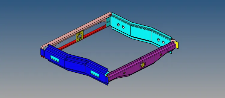
2. <!--[endif]-->In this component, there are nine different parts present. So select each part one by one and follow the steps given below.
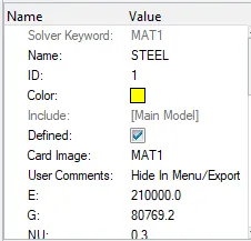
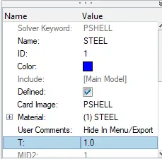
3. <!--[endif]-->Assign the material and properties to all the component. Also assign thickness to it.
4. <!--[endif]-->Now proceed for meshing the component. Here meshing will be done by following the steps given below: Go to 2D> automesh option and enter the given element size as 5 units. Then choose the mesh type as ‘mixed’ and select all the surfaces one by one. Then execute the meshing by clicking on mesh option.
5. <!--[endif]-->After mesh is generated on the component , assign the given quality criteria by going to the Tools>check elems>settings>Criteria editor and enter the given quality criteria and apply.
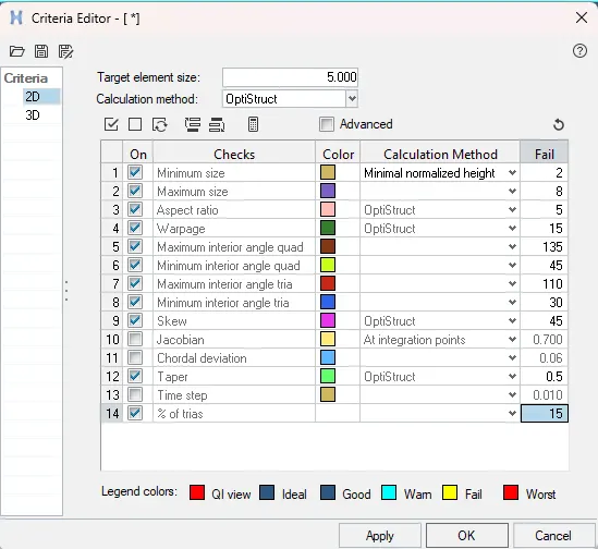
6. Then refine the mesh by using cleanup tools option present in the quality index section.
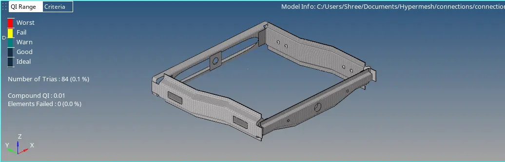
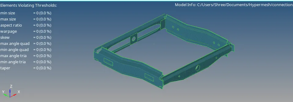
7. <!--[endif]-->After that, smooth option is used to get good quality mesh flow.
2. <!--[endif]-->Deploying Connections:-
<!-- [if !supportLists]-->1. <!--[endif]-->Right_Rail_2 & Front_truss_1:- Seam-Quad(angled+capped+L)
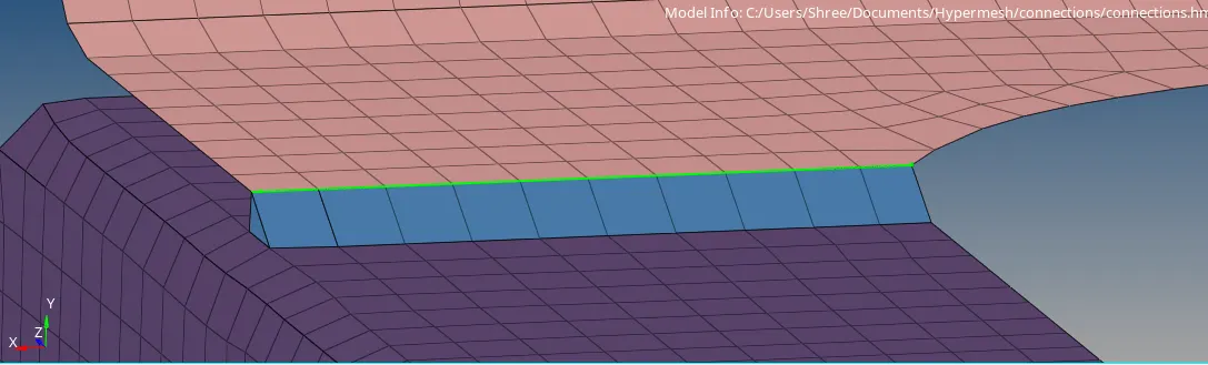
For Seam welding, go to 1D>connectors>seam and select the nodes along which connection has to be deployed. Then enter the spacing value as target length and select the components to be welded. Then select the type of weld as Seam-Quad(angled+capped+L) and enter tolerance, weld angle, cap angle and runoff angle as per the requirement. Then click on create.

Now to know whether our connection is realized or not, check for the colour of connection. If it is green in colour, connection is realized. If it is yellow, then connection is unrealized and if it is red in colour, then connection is failed.
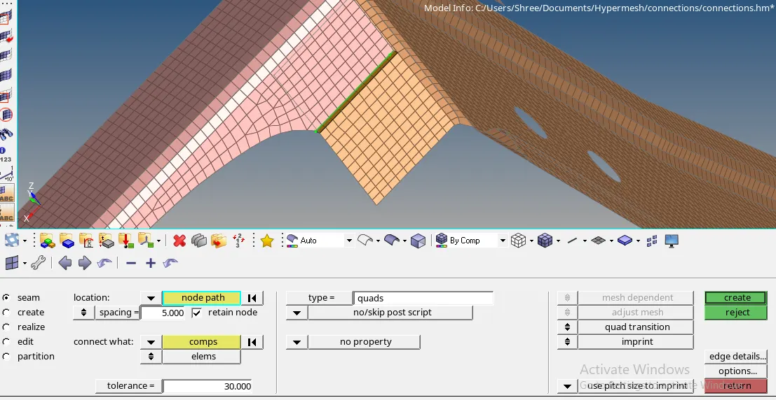
2. <!--[endif]-->Left_Rail_2 & Front_truss_1:- Quad elements
For Seam welding, go to 1D>connectors>seam and select the nodes along which connection has to be deployed. Then enter the spacing value as target length and select the components to be welded. Then select the type of weld as quads and click on create.
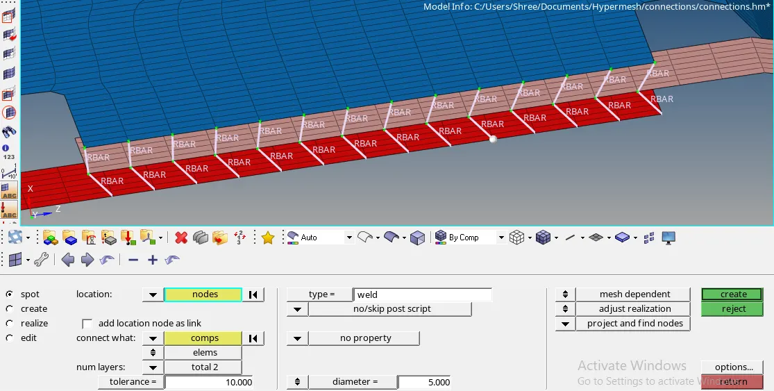
3. <!--[endif]-->Front_truss_2, Front_truss_1 & Right_Rail_1:- Spot weld with 2 Layers and 5 mm Diameter
For spot weld, go to 1D>connectors>spot select the nodes along which connection has to be deployed. And select the components to be welded. Then select the type as weld and enter tolerance and diameter value as per the requirement. Select the number of layers as 2 and then click on create.
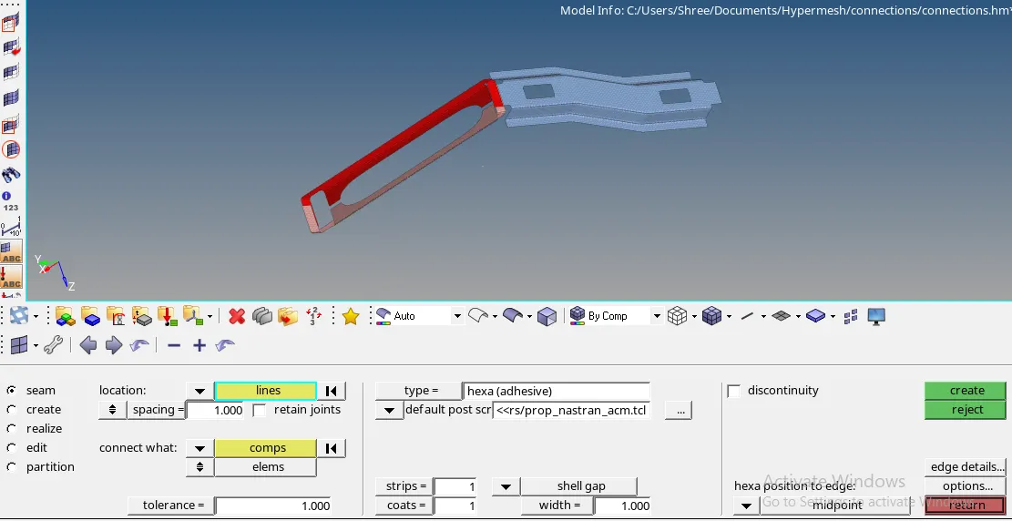
4. <!--[endif]-->Front_truss_2, Front_truss_1 & Left_Rail_1:- Hexa (Adhesive)
For this connection, go to 1D>connectors>seam and select the nodes along which connection has to be deployed. Then enter all the required parameters and select the components. Then select the type as Hexa (Adhesive) and click on create.
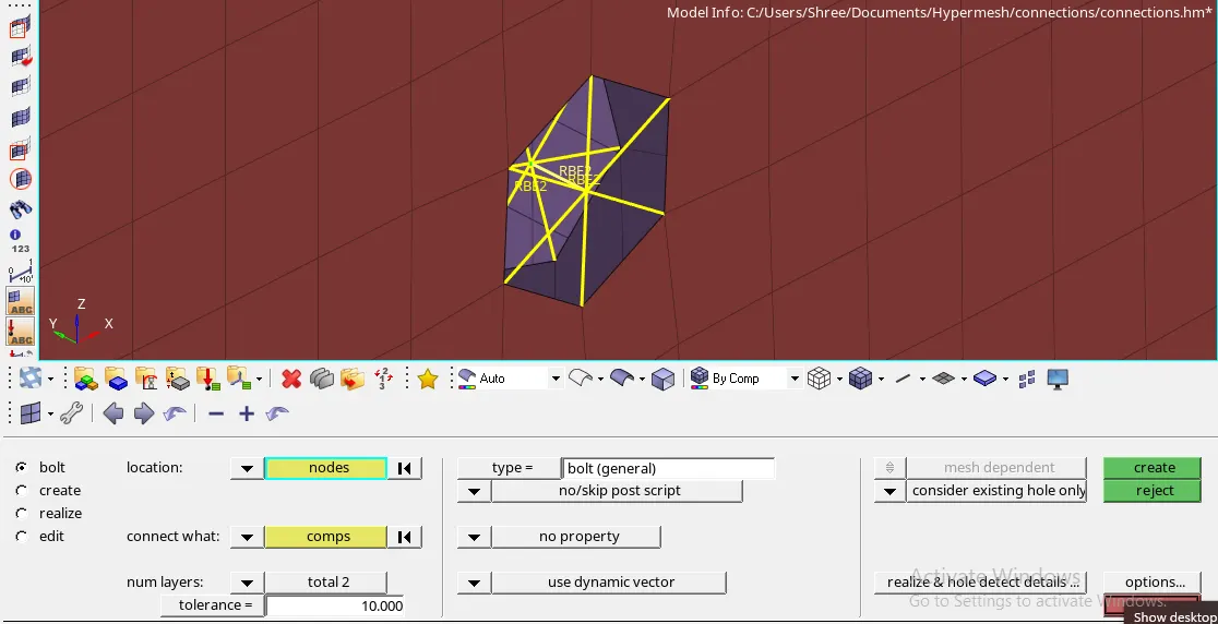
5. <!--[endif]-->Rear_truss_2 & Right_Rail_2 and
6. Rear_truss_2 & Left_Rail_2:- Bolt Connector
For these connections, go to 1D>connectors>bolt and select the nodes along which connection has to be deployed. Then enter all the required parameters and select the components. Then select the type of as bolt(general) and click on create.
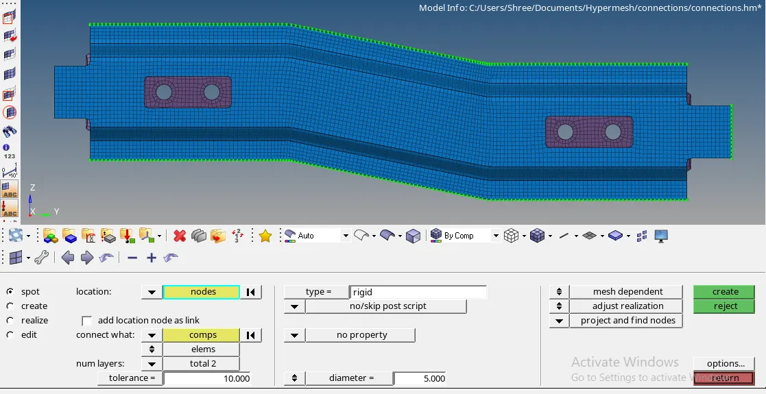
7. <!--[endif]--> Right_Rail_1 & Right_Rail_2:- Spot-weld with Rigid Elements
For this connection, go to 1D>connectors>spot and select the nodes along which connection has to be deployed. Then enter all the required parameters and select the components. Then select the type as rigid and click on create.
<!-- [if !supportLists]-->8. <!--[endif]-->Left_Rail_1 & Left_Rail_2:- Spot-weld with Spring Elements
For this connection, go to 1D>connectors>spot and select the nodes along which connection has to be deployed. Then enter all the required parameters and select the components. Then select the type as spring and click on create.
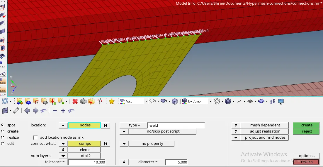
9. At last, rest all the components left where we think connections are required, join them with suitable connectors.
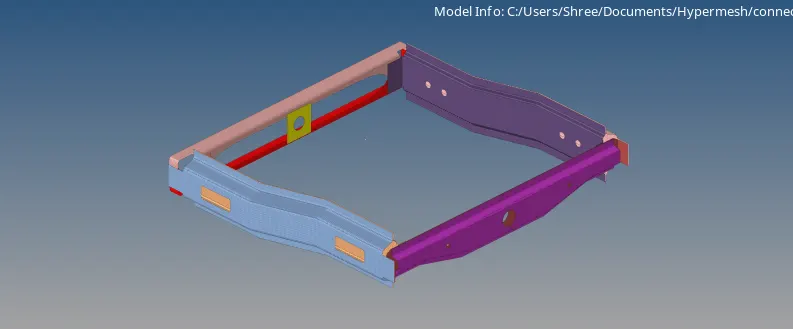
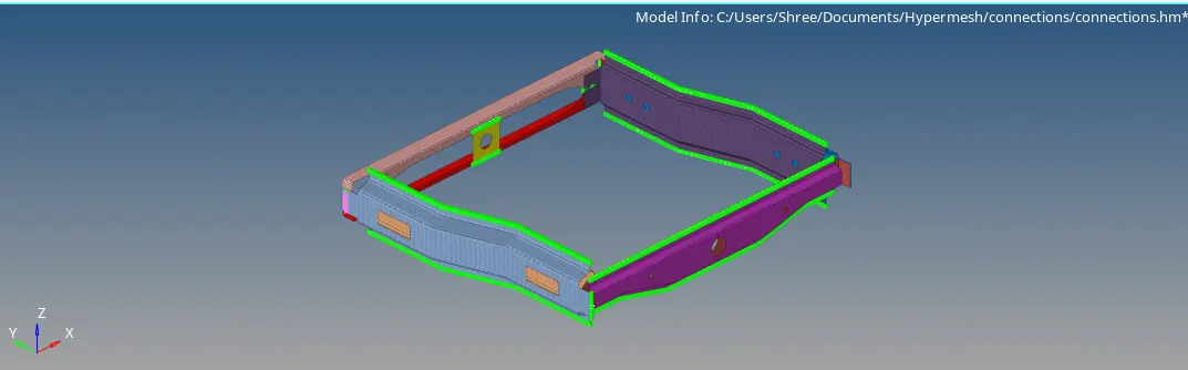
Final model image:
LEARNING OUTCOMES:
1) Performing this challenge enables to use different tools in the software.
2) Learn to deploy connections at various locations.
3) Knowing about the uses and applications of deploying connections in modeling.
CONCLUSION: After meshing the model according to the given quality criteria and performing systematic approach, required connections are applied successfully to the given model.