Week 7-12-Creation of 1D Connectors Challenge
Week 12-Creation of 1D Connectors Challenge
1. Aim
- To Generate a mesh on a given geometry.
- Ensure the generated mesh obeys the mentioned quality criteria.
- Create mentioned connectors and Attach the various parts of the given model.
Objective
- Mesh the generated mid-surface and reconstruct the mesh to satisfy the following quality criteria.
- Model Checks
Quality Criteria
| Sl No: | Quality Criteria | Value |
| 1 | Target Element Length | 5 |
| 2 | Aspect Ratio | 5 |
| 3 | Skewness | 45 |
| 4 | Warping | 15 |
| 5 | Taper | 0.6 |
| 6 | Min. Length | 2 |
| 7 | Max. Length | 8 |
| 8 | Min. Angle Quad | 45 |
| 9 | Max. Angle Quad | 135 |
| 10 | Min. Angle Tria | 30 |
| 11 | Max. Angle Tria | 110 |
| 12 | Tria% | 15 |
- Construct and oin parts using specified components.
1. Right_Rail_2 & Front_truss_1:- Seam-Quad(angled+capped+L)
2. Left_Rail_2 & Front_truss_1:- Quad elements
3. Front_truss_2, Front_truss_1 & Right_Rail_1:- Spot weld with 2 Layers and 5 mm Diameter
4. Front_truss_2, Front_truss_1 & Left_Rail_1:- Hexa (Adhesive)
5. Rear_truss_2 & Right_Rail_2:- Bolt Connector
6. Rear_truss_2 & Left_Rail_2:- Bolt Connector
7. Right_Rail_1 & Right_Rail_2:- Spot-weld with Rigid Elements
8. Left_Rail_1 & Left_Rail_2:- Spot-weld with Spring Elements
9. Rest all the components left Join them with suitable connectors
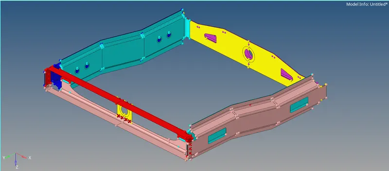
Fig 01: Isometric View Of Model.
3. Procedure
Step 1: Import and Perform Meshing
Import the model to hyper mesh. As we inspect the model, it is already a mid-surface of the geometry. So we can directly go for meshing. Add quality criteria and mesh the geometry. The model consists of 09 different components. Check for quality criteria and model checks, if any failing elements are present in the mesh. And rectify errors if there are any.
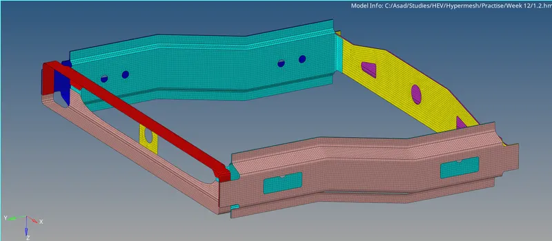
Fig 02: Generated Mesh
Step 2: Realising Proper Connectors Between Components.
1. Right_Rail_2 & Front_truss_1:- Seam-Quad(angled+capped+L)
The connecter option makes the 1D connectors. Here, the connectors are Seam type connectors. For creating connectors,
- 1D >> Connectors
The Seam connectors are created by
- Seam >> Seam >> Location =Nodelist From Target Component, where need the connection. >> Spacing= 5 (Target Element Length) >> Connect What= Select Both Components >> Type= Seam-Quad(angled+capped+L) >> Tolerance =10 >> Create.
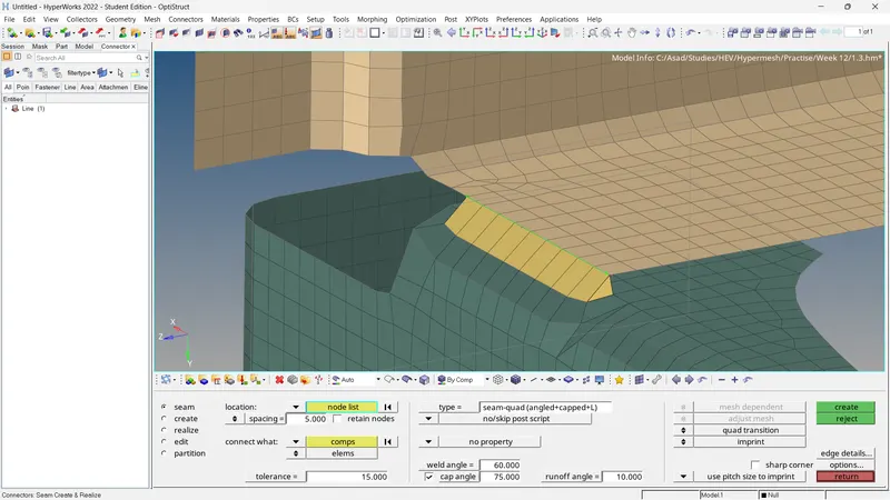
Fig 02: Right_Rail_2 & Front_truss_1:- Seam-Quad(angled+capped+L)
After the connection, the neighbouring elements will be disturbed. Correct the mesh flow and rectify element failures.
2. Left_Rail_2 & Front_truss_1:- Quad elements
- Seam >> Seam >> Location =Nodelist From Target Component, where need the connection. >> Spacing= 5 (Target Element Length) >> Connect What= Select Both Components >> Type= Quads >> Tolerance =10 >> Create.
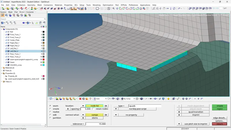
Fig 03: Left_Rail_2 & Front_truss_1:- Quad elements
3. Front_truss_2, Front_truss_1 & Right_Rail_1:- Spot weld with 2 Layers and 5 mm Diameter
Here, the connector type is spot weld type. The number of layers is equal to 2. So end components are connected to the mid component separately.
- Spot >> Spot >> Location =Nodelist From Target Component, where need the connection. >> Connect What= Select Both Components >> Num Layers = total 2 >> Type= Weld >> Diameter=5 mm >> Tolerance =10 >> Create.
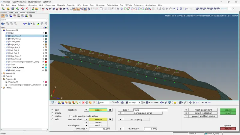
Fig 04: Front_truss_2, Front_truss_1 & Right_Rail_1:- Spot weld with 2 Layers
4. Front_truss_2, Front_truss_1 & Left_Rail_1:- Hexa (Adhesive)
- Seam >> Seam >> Location =Nodelist From Target Component, where need the connection. >> Spacing= 5 (Target Element Length) >> Connect What= Select Both Components >> Type= Hexa (Adhesive) >> Tolerance =10 >> Create.
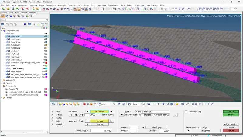
Fig 04: Front_truss_2, Front_truss_1 & Left_Rail_1:- Hexa (Adhesive)
5. Rear_truss_2 & Right_Rail_2:- Bolt Connector
Here the connectors are done with bolts
- Bolt >> Bolt >> Location =Nodelist From Target Component, where need the connection. >> Connect What= Select Both Components >> Num Layers = total 2 >> Type= Bolt (General) >> Create Holes, If None >> Tolerance =10 >> Create.
The holes generated can affect the mesh flow. Using the rotate option to rotate nodes in the y-axis to align them to the mesh flow.
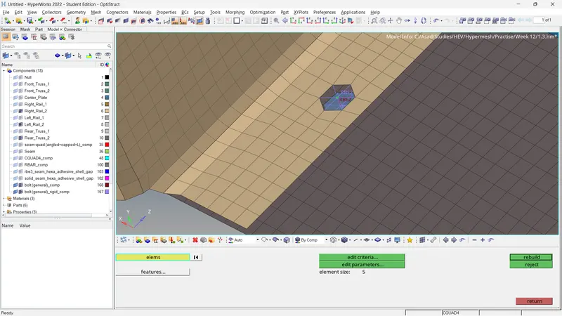
Fig 05: Rear_truss_2 & Right_Rail_2:- Bolt Connector
6. Rear_truss_2 & Left_Rail_2:- Bolt Connector
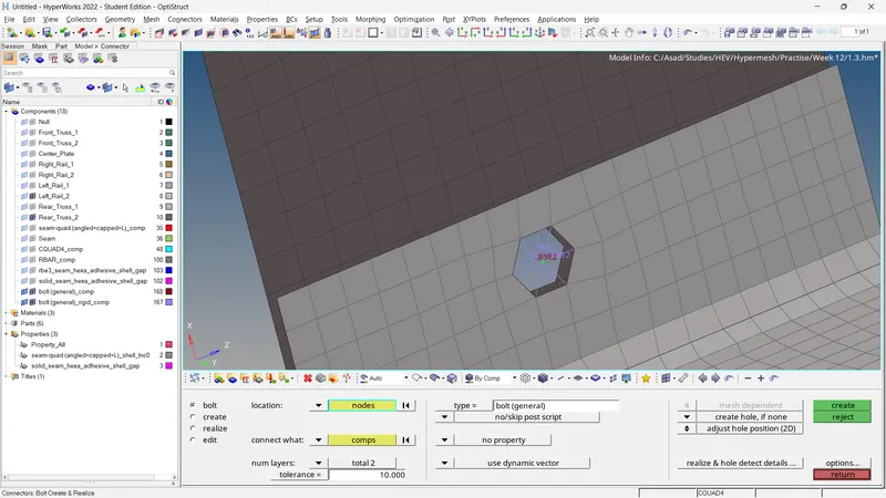
Fig 06: Rear_truss_2 & Left_Rail_2:- Bolt Connector
7. Right_Rail_1 & Right_Rail_2:- Spot-weld with Rigid Elements
- Spot >> Spot >> Location =Nodelist From Target Component, where need the connection. >> Connect What= Select Both Components >> Num Layers = total 2 >> Type= Rigid >> Tolerance =10 >> Create.
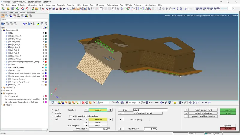
Fig 07: Right_Rail_1 & Right_Rail_2:- Spot-weld with Rigid Elements
8. Left_Rail_1 & Left_Rail_2:- Spot-weld with Spring Elements
- Spot >> Spot >> Location =Nodelist From Target Component, where need the connection. >> Connect What= Select Both Components >> Num Layers = total 2 >> Type= Spring >> Tolerance =10 >> Create.
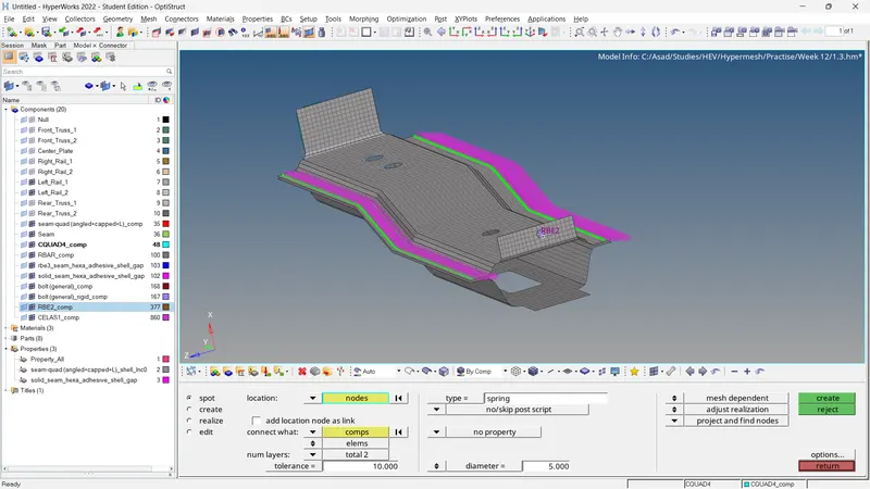
Fig 08: Left_Rail_1 & Left_Rail_2:- Spot-weld with Spring Elements
The remaining connections are done using appropriate connections. At last check for quality criteria.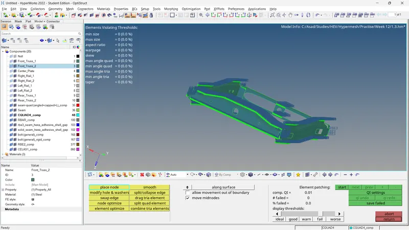
Fig 09: Quality Checking
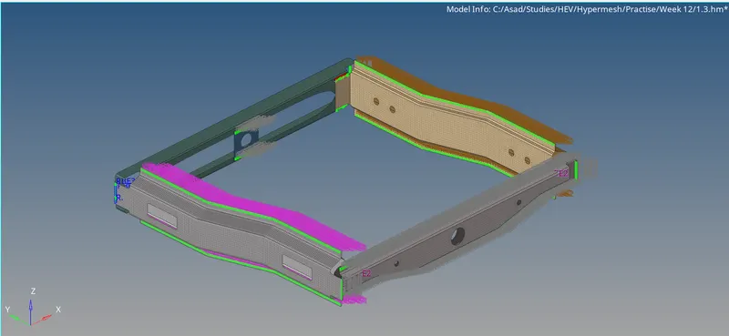
Fig 10: Final Result
4. Observations
- The mesh is generated with the following quality criteria and target element length.
- Using appropriate connectors, the connections are made throughout the model.
- Quality checking is completed
5. Results
- The mesh is generated and the connections are created with mentioned connector types.