Week-6 : Turbocharger Modelling
Aim:
- List down different TC and locate examples from GT Power
- Exploring Tutorial 6 and 7
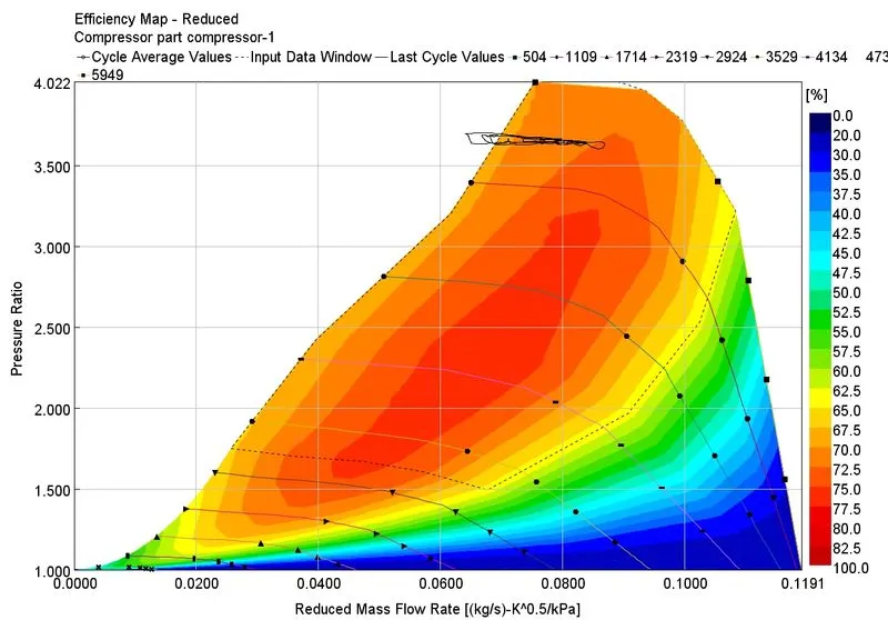
- Plotting Operating points for Compressor and Turbine maps
- In which application Variable Geomtery Turbine is beneficial
- Explore example-Diesel VGT and understand the modelling part
Turbochargers
1.Fixed Geometry Turbocharger- This is the simplest form of turbocharger whose geometry is fixed.We cannot control the geometry and speed of the turbine or compressor of thiss turbocharger which makes it prone to the mechanical failure at very higher speed.
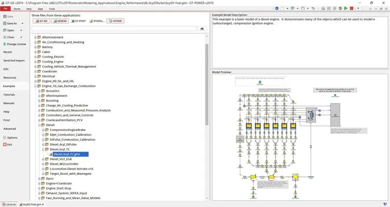
2. Wastegate turbocharger: In this type of turbocharger the amount of exhaust gas going to the turbine can be controlled by a small opening called wastegate.Due to this mechanism the speed of the turbine can be controlled and hence can be prevented to mechanical failure.
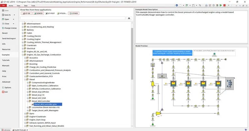
3.Variable Geometry Turbocharger or VGT: In this type of turbocharger there are vanes around the turbine entry which controls the amount of exhaust gases entering into the turbine inlet.So in that way we can control thee rpm of the turbine and hence the compressor.This is the most advanced version of the turbocharger and hence most costly.
Tutorial 6
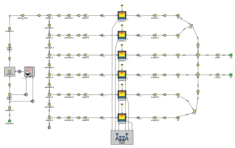
The cylinder geometry are as follows:
Bore= 100mm.
Stroke= 100mm.
Connecting rod length = 220mm.
Compression ratio = 16.5
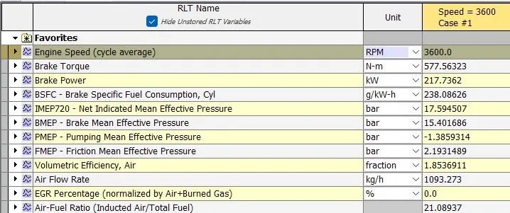
Performance Characteristics
Tutorial 7
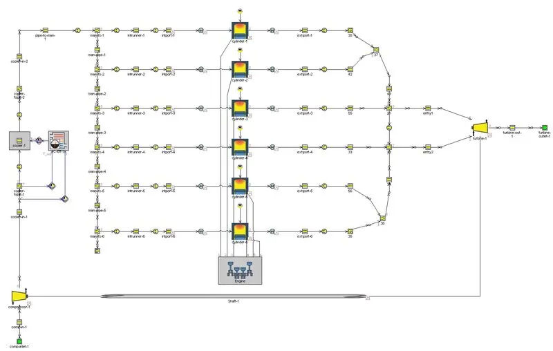
The cylinder geometry are as follows:
Bore= 100mm.
Stroke= 100mm.
Connecting rod length = 220mm.
Compression ratio = 16.5
Moment of Inertia of Shaft= 0.0005kgm^2
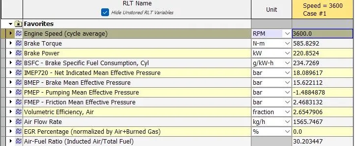
Performance Characteristics
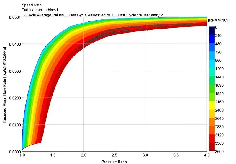
Operating Point Map
Turbine
Compressor
Variable Geometry Turbine is beneficial in- VGT devices are designed to increase boost pressure at low speeds, reduce response times, increase available torque, decrease the boost at high engine speeds to prevent over-boosting, reduce engine emissions, improve fuel economy and increase the overall turbocharger operating range.
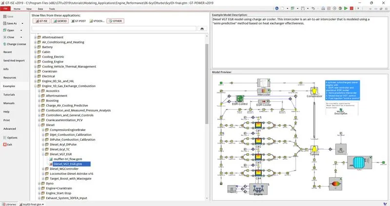
Diesel VGT EGR
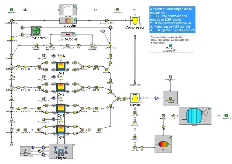
The example 'Diesel_VGT_EGR' demonstrates several modeling concepts important for automotive diesel engines, including variable geometry turbine, boost control, intercooler, EGR circuit with cooler and EGR rate control, injection limiting for smoke control, and exhaust after treatment device modeling.
The Engine
The engine is a 4-cylinder, four-stroke, direct injection, 2L diesel engine. The engine runs in "speed" mode, where the engine speed is entered by the user and the engine torque is calculated. Combustion is modeled by the DIPulse method. In-cylinder heat transfer is modeled using the Woschni model. A FE model is used to predict the cylinder, head and piston temperatures.
The Intake System
The intake system consists of the air piping upstream of the compressor inlet, and contains a simple model of an air box. The air box is modeled as a group of interconnected flowsplits that represent the total volume of the air box. At the inlet and outlet of the air box, "bellmouth" orifice connections are used to model smooth transitions.
The Intercooler
The intercooler is found downstream of the compressor outlet. The Number of Identical Pipes attribute is used to model a bundle of 25 identical pipes of 7.0 mm diameter each. The pressure drop across the intercooler is calibrated using the Friction Multiplier in the in the pipe. Flowsplits are required to model the inlet and outlet of the intercooler since pipes cannot connect to pipes with the Number of Identical Pipes attribute greater than one. The desired intercooler outlet temperature is calculated by a simple control system and is imposed by actuating the wall temperature of the intercooler pipe. The Heat Transfer Multiplier in the pipe is increased to a large enough value so that the outlet temperature matches the wall temperature. The desired outlet temperature is calculated in a 'IntercoolerEff' part from the effectiveness table of the intercooler.
Conclusion:
- With use of Turbo charger we can see an increase in the Maximum Power and Torque value.
- Also there is a drastic increase in A/F ratio due to entering of high density compressed air beacause of presence of Compressor.
- This led to decrease in BSFC due to presence of Turbine driven by exhaust gas velocity.
- The increase in Air flow rate can also be seen due to presence of Compressor.