Week 6-Meshing of Hood Challenge
challenge-6: Extracting the mid-surface and meshing of the hood.
Objective: To extract the mid-surface from the given geometry(hood) and mesh the surface using the mixed elements with given quality criteria and element length and assign thickness to it.
the given geometry is a hood, The hood is an integral part of a car that covers and protects the engine in a front-engine vehicle. While the outer panel acts as the car’s skin, the inner panel serves as a sound dampener that can eliminate or decrease typical engine noises.we will be meshing the given car hood for crash analysis with mixed element.
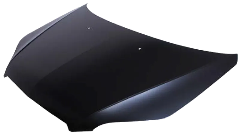
img:hood of the engine
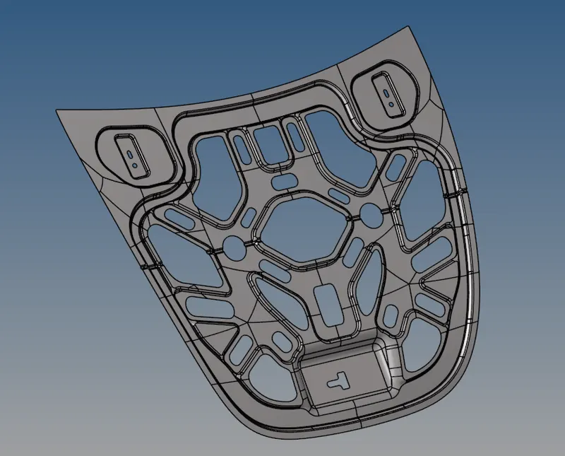
img: inner panel original model image
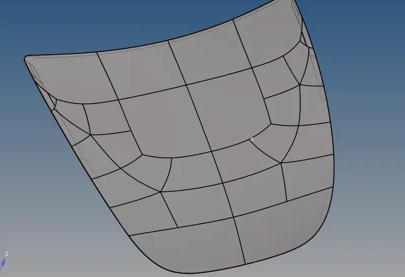
img:outer extract of the hood
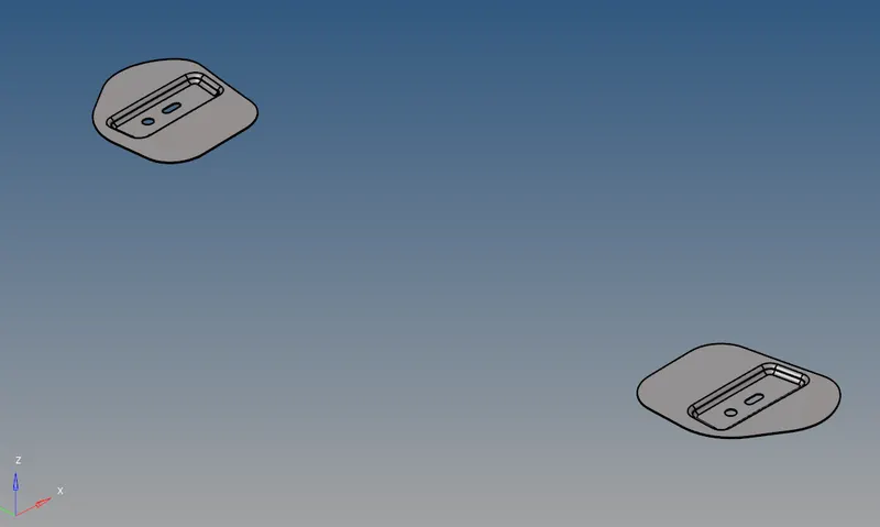
img:hinge of the hood
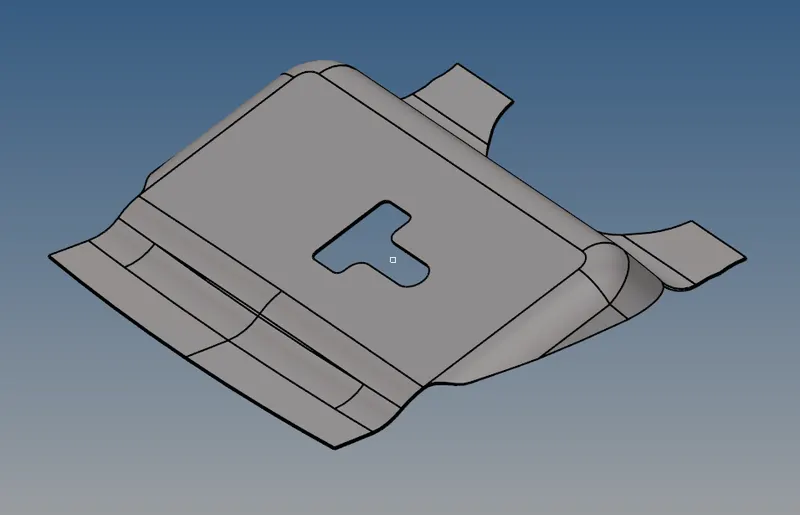
img:latch from the hood
procedure:
- first import cad model(hood) to the hypermesh by going to import ⇀ import geometry⇀ hood(stp file)⇀and click import.
- once the hood file is imported extract the mid surface through the offset method by going to surface edit⇀ offset⇀and select the surface which you want to offset.before offsetting duplicated the surface and again select the surface by face and enter the half of the original thickness value and check the normal and offset to its midplane.
- Hide the remaining parent parts and unhide the inner panel and extract the mid surface by the offset method
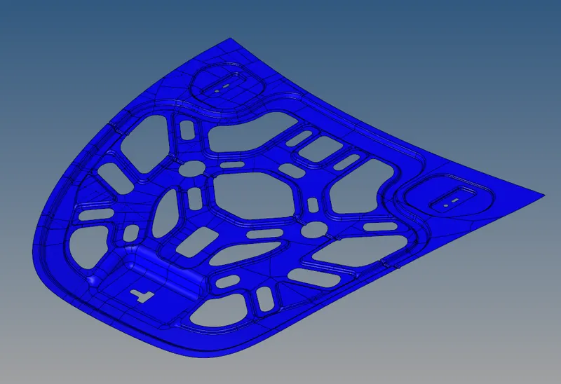
img:extracted midsurface of the hood
- once the extraction is done mask the solid component using mask option and organize the mid surface to new component from the original component by going to : tool⇀ organize ⇀ click the surface ⇀ select the destination ⇀ and select 'move'.
- now hide any other solid and surface component other than midsurface of the inner panel.
- before meshing of the inner panel check the component if there is any error.
- separate the pannel with lines'by using either split surface node or split surface line which can be accesed by geometry ⇀ quick edit ⇀ split surface line or split surface node. by using eirther of this option we can create a split line inbetwwen the inner panel
- And also insert the quality criteria before meshing by going to prefrence in the window which will be available at the top prefrence ⇀ criteria file setting.
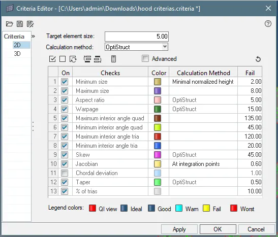
img:critieria file setting
- go to the 2D ⇀ automesh ⇀ select the surface to mesh ⇀click 'ok'. choose the element size as 5 and choose mixed mode option because the hood is for crash test.
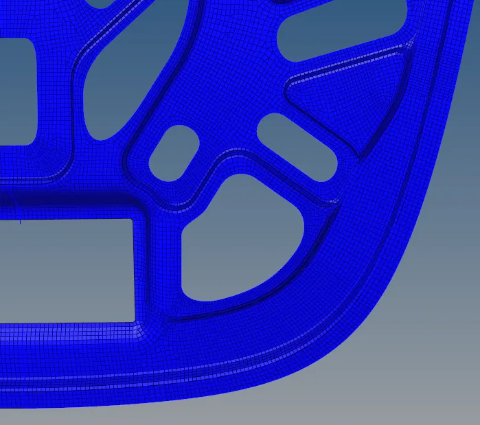
img:part of the meshed inner panel
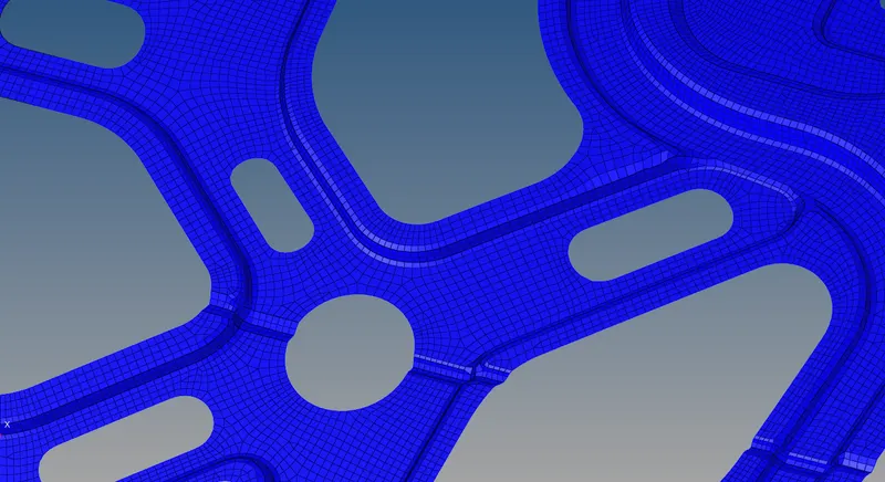
img:anothe part of the meshed pannel
- because of the symmentry we can model only on the half of the side and we will reflect the mesh to the other side once the meshing is done; tool ⇀ reflect ⇀click the elements to reflect ⇀duplicate the elements⇀select the vector and base ⇀click'reflect'.
- use smooth option for align the mesh in a good fashion manner by going to 2D⇀smooth⇀select the elements⇀and click smooth or click shift+F12, we can smooth with respect to the shape and size.
- while meshing keep on checking the eqality error and try to reduce it.
- once the model is meshed cheeck for the free edge in between the noide and elemnets because if the nodes are not connected the accuracy will not be good and the force transmission will not be good.
- we can close the free edge by two option by going F3 which is replace node option used to connect the node for free edge and also to control thr meshing error.
- free egde can be identified by going to Tool ⇀ edges⇀ click the elements and select the displayed elements⇀and click free edge.
- once the free edge is identified we can equalize it it is in the same option.
- the final inner model will look like
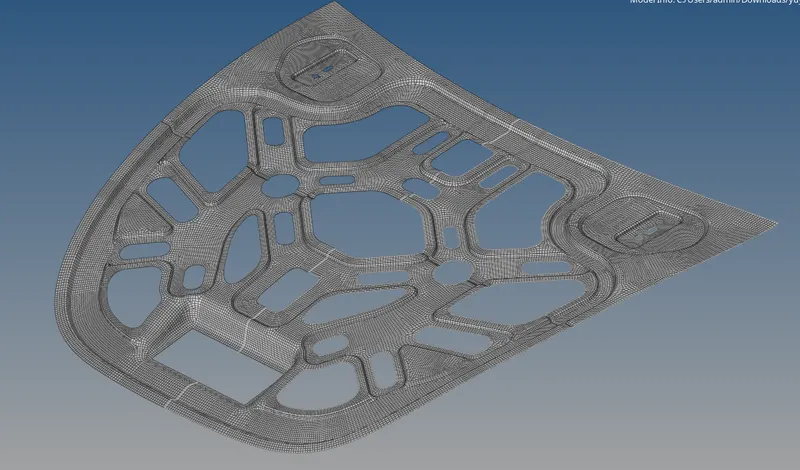
img:final meshed model of the inner panel
- same as for outer,hinge and latch , extract the midsurface in a separate component and check fot the error and mesh the surface.
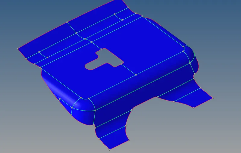
img:extracted mid surface of the latch
- check for free edge and quality error while doing mesh and try to retify it at the starting stage itself.
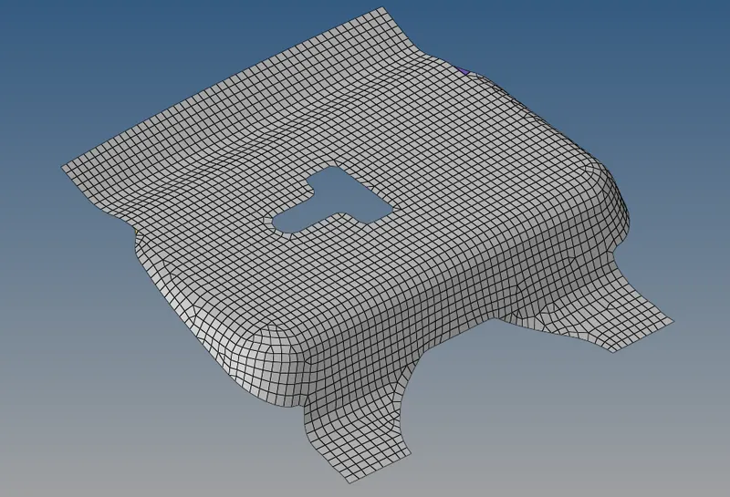
img:final mesh model of the hatch of the hood
- same for extract the surface for hinge and outer pannel and split the surface and mesh the surface
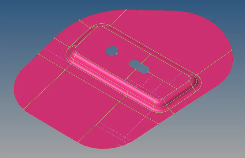
img:midsurface of the hinge on the ride side part of the hood
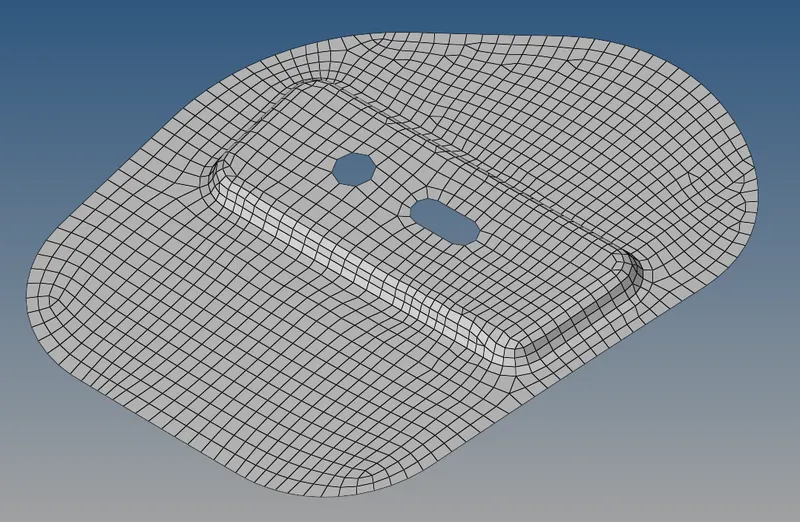
img:mesh model of the hinge
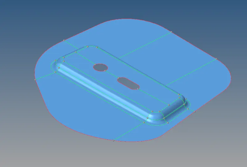
img:midsurface of the left part hinge
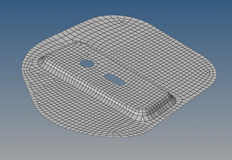
img:meshed surface of the left hinge
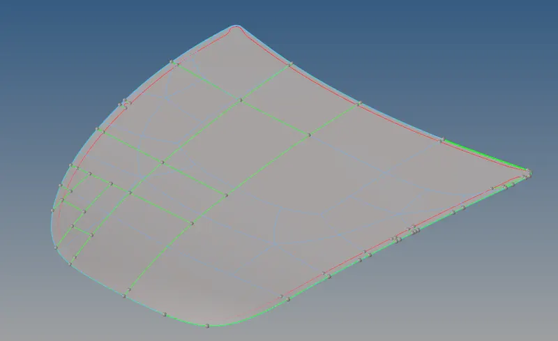
img:extract surface of the outer panel
- as the outer panel is the symmentry we can model it on only on one side and reflect the mesh on the other side.after reflecting check for the free edges and if it exist remove the free edges.
- split the geometry to get a good mesh flow pattern
- always try to remove rotating quads and back to back triangular elements.
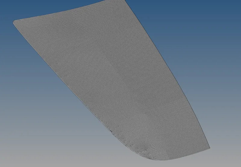
img:mesh part of the outer panel
- after meshing create a property for these components as we want to assign the thickness for this component
- go to the model bar space on the left side ,right click and choose property and rename it as t1.12 as same like crete another proiperty named T0.75 and enter the parameters in the property bar like thickness and the elements as PSHELL
- now click on the original extrcat file and assign the property to that file for respective component weith respective thickness.and select the 2D element representation to see the assigned thickness.
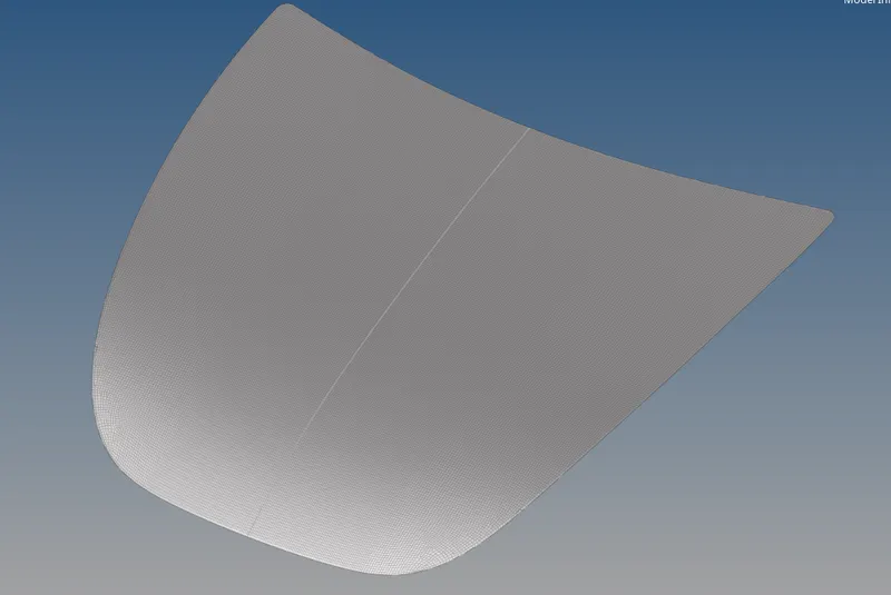
img:full meshed outer panel
result:
- the midsurface are extracted from the given model and mesh the model with mixed type of element with given element length with respect to the quality criteria.
- elements are created as per the criteria and elemets quality are improved as much as possible with minimal error
- good mesh flow pattern is achieved.
- free edges are checked and removed.
- thickness has been assigned as per the model by creating property .
result of meshed parts:
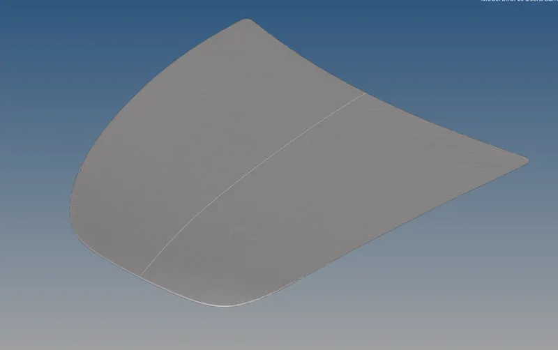
img:full meshed outer panel
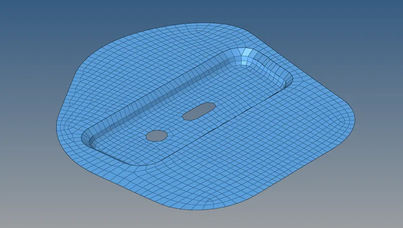
img:full meshed hinge
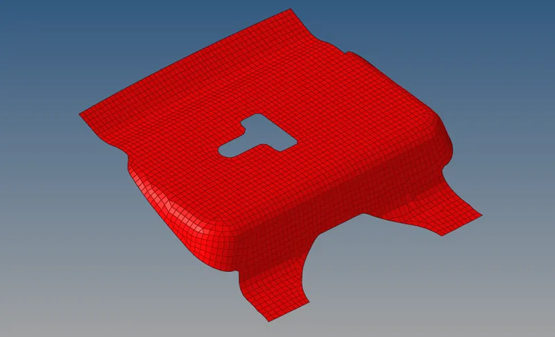
img:full meshed latch
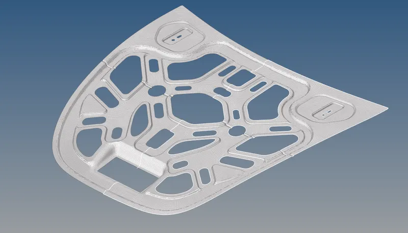
img:full meshing of inner part
learning outcome:
- learned how to extract the midsurface using surface offset method.
- learned how to import and change the criteria setting
- learned how to split a geometry to achieve a good mesh flow and mesh pattern
- learned how to assign thickness and how to check quality error and repair it.
- leaned how the minimum error in the split or geomentry error can cause large mesh pattern error.