Week 6-Meshing of Hood Challenge
AIM:
• To extract mid-surface, geometry cleanup, and deploy for the hood model components.
OBJECTIVES OF THE PROJECT:
• To extract separate mid-surface for the components.
• To perform geometry cleanup for the extracted mid-surface.
• To deploy mesh on the extracted mid-surface.
• To remove the elements failing for quality.
- To assign thickness to the components.
.
ABSTRACT
A Car hood or bonnet is a part which is located at the front end and it covers the engine of the automobile. Its function is to protect the engine. We can easily open and close the hood during repairs or maintenance. Hoods are typically made of the same material as the rest of the body work This may include steel, aluminium, fiberglass or carbon fiber. However, some aftermarket companies produce replacements for steel hoods in
fiberglass or carbon fiber to make the vehicle lighter. In this project we are going to perform geometry clean-up and mesh the hood model according to the given quality criteria using Hypermesh.
INTRODUCTION:
HOOD
Car hood mainly consists of two parts, inner bonnet and outer bonnet. Inner Bonnet usually provides strength for the engine, battery andother important parts in the front-end of the car. Outer Bonnet provides styling and gives aerodynamic shape to the car body. Various requirements are needed while designing such as safety aspects and the quality criteria.
QUALITY CRITERIA
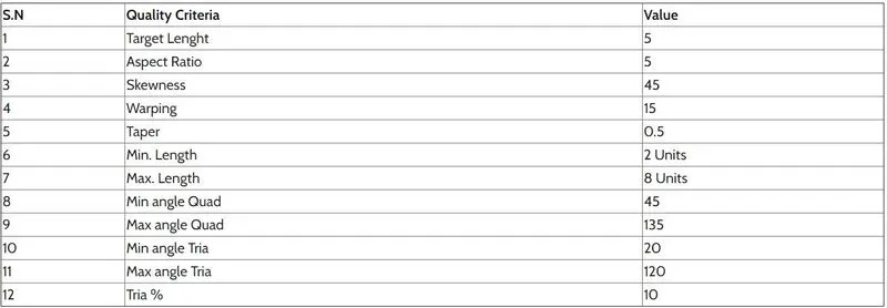
.1)Aspect Ratio: It is defined as the ratio of maximum element edge length to the minimum element edge length. The ideal value is 1 but less than 5 is acceptable.
2)Minimum/Maximum element length: It is very important to check this error as it is used for crash analysis check.
3)Jacobian: It is the scale factor used in the transformation of a coordinated system. The ideal value is 1 but greater than 0.6 is acceptable.
4)Skewness: If the quad element is not a square and has deformation, skewness is defined as 90 minus the minimum angle between the two lines
joining the apposite mid sides of the element and similarly for the triangular element it is 90 minus the line between the each node of the
opposing mid side. The ideal value is less than zero but 45 degree is acceptable.
5)Warp Angle: It is defined as the angle between normals of two triangular planes formed by splitting the quad element along diagonals.
PROCEDURE
- The given component is imported as STEP format file.
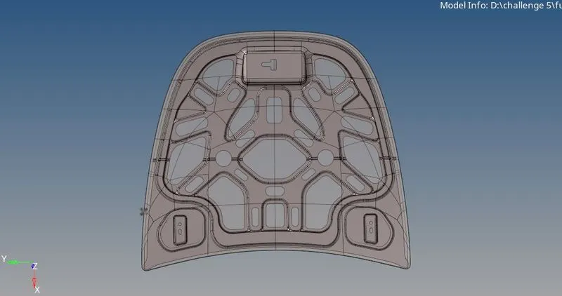
- The hood file has 5 small componenets such as Outer extract, inner extract, 2 hinge reinforcement and a latch reinforcement of a hood.
- The mid-surface is extracted for all the 5 components using the midsurface option in geometry section and the displaying mode is changed from auto to by topo.
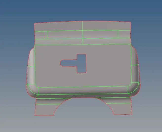
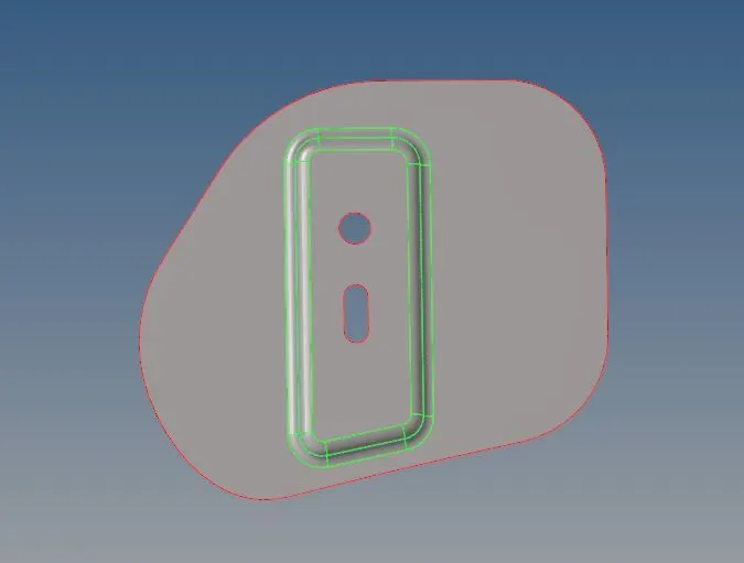
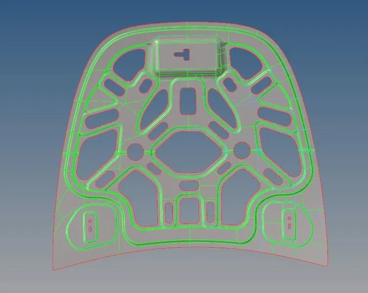
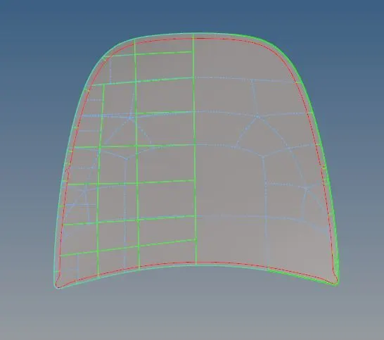
- The solid in the components are deleted by selecting the solids in the component and using the delete option. On deleting the solids only the surfaces will be available in the component.
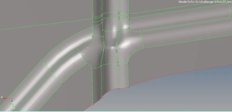
- In the given components middle surface, the cleanup is done in which certain edges are toggled for proper mesh flow and satisfying the quality criteria and they are done using the toggle edge option in quick edit.
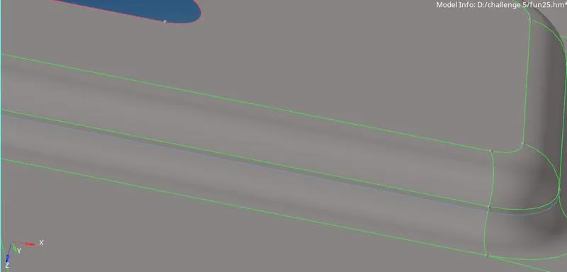
- Toggle the unwanted lines and split the component in to small pieces for meshing as per our requirement .
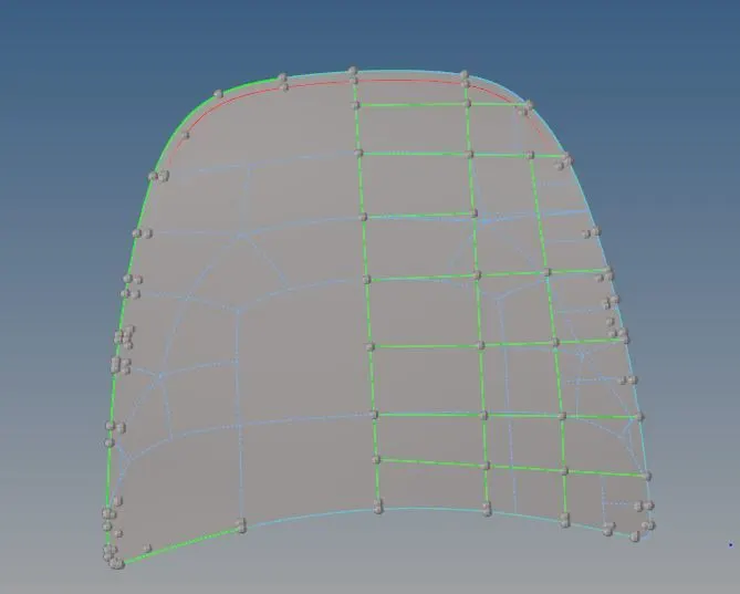
- For irregular surfaces we can delete them permenantly and recreate them with new surfaces.
-
Select all the unnecessary surfaces and delete them.We can release all the point for better visualisation.
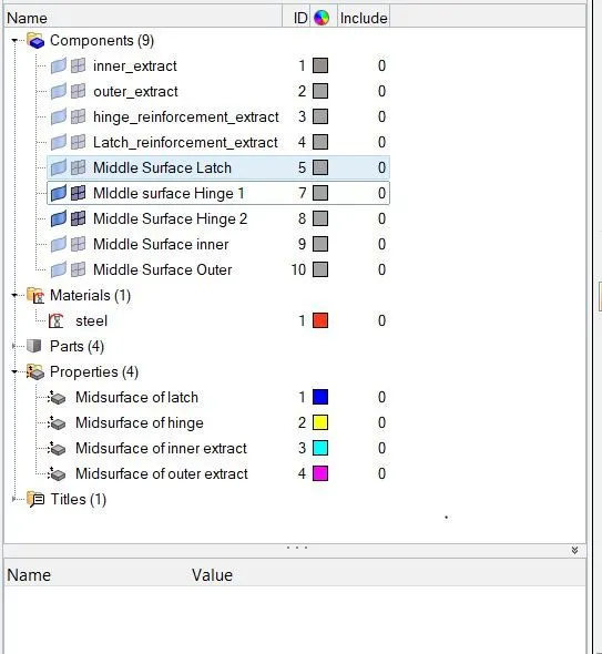
- Once the midsurfaces are created we can assign thickness to them by creating properties. Hence we created property for each component, we also created a material namely Steel and assigned it to properties. We assigned of the geometry to the properties. Once such example is shown below.
-
The edges can also be extended for proper mesh flow using the split surface-line option and the node points can also be added or removed by using the add/remove points option in quick edit.
-
The components are meshed one by one in the order of latch reinforcement, hinge reinforcement, outer extract and finally the inner extract.
-
The meshing process is carried using the automesh option in the 2D section and the mixed elements is used here for meshing. The target element size followed here is 5.
-
The above given quality criteria are given as input in the check elements option in the tools section.
-
On meshing the components are meshed with quads and trias and the mesh is made proper by following various processes.
-
The mesh with the rotating quad elements are made proper by selecting the rotation quads along with the nearby elements and remeshing them using the automesh option.
-
. The elements are aligned in a line by aligning the nodes of the elements using the align node option in node edit.
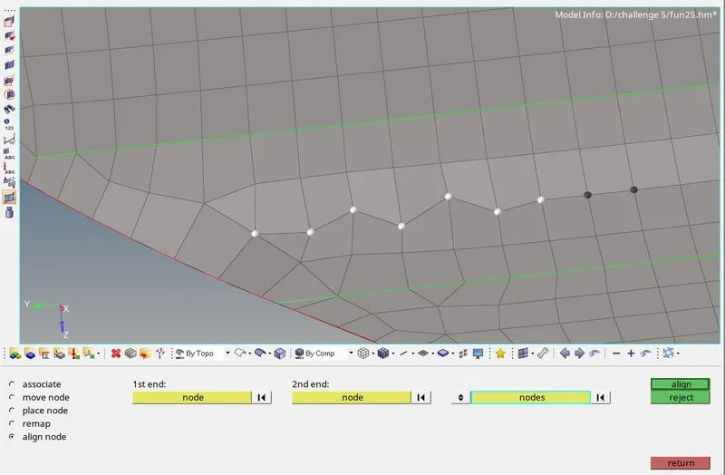
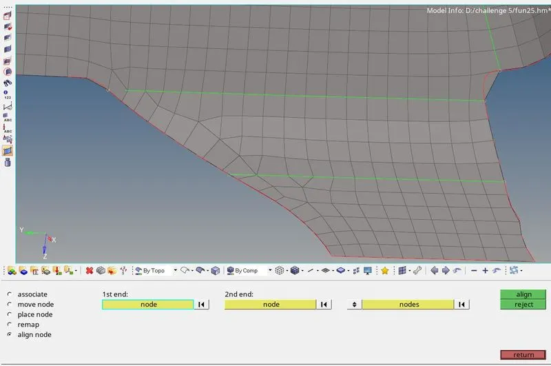
The meshed elements are frequently checked for satisfying quality criteria by using the check elements option in which the warpage, skew, length etc are checked for failures in the elements.

- The failed elements are then saved using the save failed option and are retrieve masked and reversed using the mask option to display only the failed elements.
-
Then the adjacent elements to the failed elements are unmasked using the unmask adjacent and the optimizing process is carried out.
-
The failure of elements on quality criteria are made proper by various methods depending on the element failure in the mesh. The various methods followed to remove the failed elements in the mesh are :
-
By using place node in quality index in which the node of an element can be moved to optimize the element.
-
By using the element optimize option in quality index in which the element will be optimized based on the given quality criteria.
-
By using the split & combine element in the edit element option in which a quad element can either be splitted into two trias or vice-versa.
-
. By using the smooth option in the 2D section, the elements can be selected and on performing this option the selected are made smoother by aligning the elements in a proper mesh flow with respect to the adjacent mesh flow.

-
In case of any failure, translate option can also be used to fix the nodes of the element and the project option is used to fix the failures in the nodes of an element.
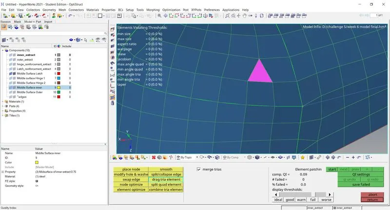
- In case of any 2 opposite trias are found in the mesh, the 2 trias are made closer by using drag tria element in quality index and the trias are remeshed for removing them.
-
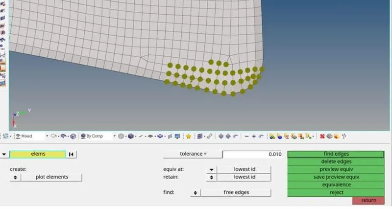
On meshing all the 5 components using the above steps, the free edges in the components are found using the edges option in the tool section and the free edges are deleted and made equivalence.
-
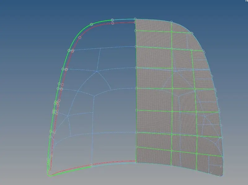
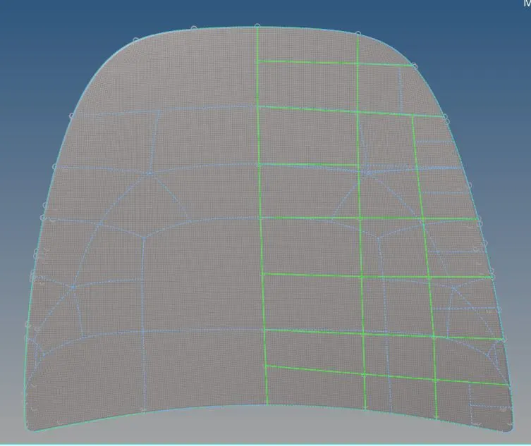
The inner extract component is a symmetric component therefore one half of the component is alone meshed and the mesh on the one halfis mirrored on the other half using the reflect option on selecting the vector nodes and the base node on the component.
-
Therefore all the 4 components in the given hood are meshes properly under the given quality criteria.
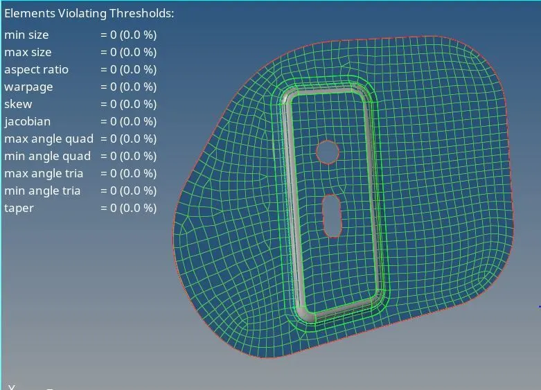
Hinge
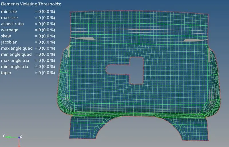
Latch
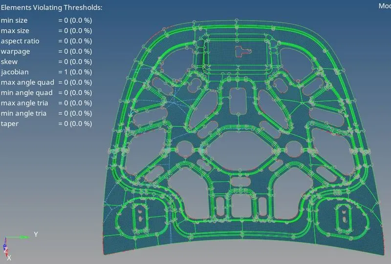
Inner Extract
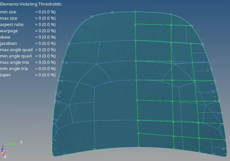
Outer extract
RESULT
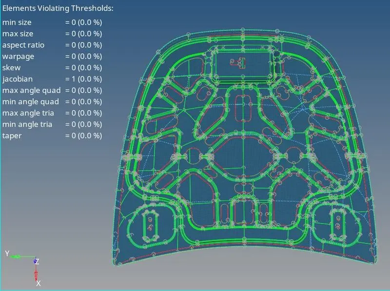
Below are images of model after meshing and element correction
Conclusion
Hereby the given model has been meshed with given quality criteria. The thickness has been applied to the parts. Mesh generated has been checked for any failing elements has been corrected.
Learning Outcome:
By completing this we learned to create the midsurface, defeaturing of midsurface, creating mesh and removing failing elements. And making mesh better using various tools.