Week 6-Meshing of Hood Challenge
Week 6-Meshing of Hood Challenge
1. Aim
- To Generate a mesh on a given model after a proper geometry cleanup and mid-surface generation using Hypermesh.
- Ensure the generated mesh obeys the mentioned quality criteria and the corresponding thickness of each surface assigned to the mesh.
2. Objective
- Import and perform a geometry cleanup on the given model using Hypermesh.
- Generate a Proper mid-surface with the proper technique.
- Mesh the generated mid-surface and reconstruct the mesh to satisfy the following quality criteria.
- Model Checks
Quality Criteria
| Sl No: | Quality Criteria | Value |
| 1 | Target Element Length | 5 |
| 2 | Aspect Ratio | 5 |
| 3 | Skewness | 45 |
| 4 | Warping | 15 |
| 5 | Taper | 0.5 |
| 6 | Min. Length | 2 |
| 7 | Max. Length | 8 |
| 8 | Min. Angle Quad | 45 |
| 9 | Max. Angle Quad | 135 |
| 10 | Min. Angle Tria | 20 |
| 11 | Max. Angle Tria | 120 |
| 12 | Tria % | 10 |
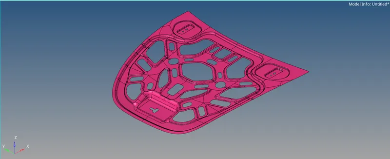
Fig 1: Isometric View Of Model.
3. Procedure
Step 1: Importing the File
First We have to import the file to hyper mesh. Here, the file is in IGES format.
- File >> Import >> Geometry >> Browse the file location >> Select The File >> Import.
Step 2: Geometric Cleanup and Extracting Midsurface.
After importing the model, clean up the geometry using auto cleanup. It will correct any errors in the geometry. After that, generate the mid-surface using the mid-surface option. Here we choose the extraction option as 'offset+planes'.
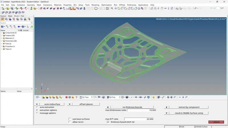
Fig 2: Mid Surface Extraction
By inspecting the mid-surface, there should be some surfaces that are missing, the 'ruled' option can address it. Also, we can create some washer splits on the edges of holes for better mesh flow. Also toggles the
lines that affect the mesh flow.
Here the geometry is symmetric. So we can divide and mesh half of the mid-surface and mirror it to the other side.
Step 3: Property, Material, Measuring Parameters and Quality Criteria
By measuring the thickness using the 'dimensioning' tool, the thickness measured 0.7 units and 0.8 units. So we take the thickness of the geometry as 0.75 Units. 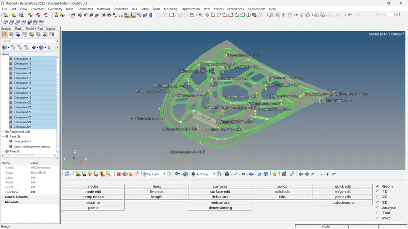
Fig 3: Thickness Measurement
So considering that thickness, create the property and the material for the mid surface. Then we have to assign the measuring parameters and quality criteria for the mesh. We can also go for automatic thickness measurement. But in this case, we choose manual thickness measurement instead of it.
For adding quality criteria,
- Preferences >> Criteria File Setting >> Input the Mentioned Quality Crieria >> Ok
For Measurement Parameters,
- Preferences >> Parameters File Setting >> Input the Target Element Length >> Ok
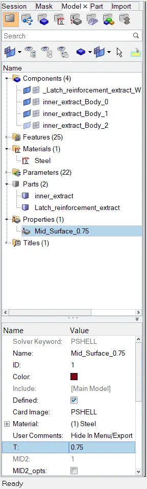
Fig 4: Property and Material
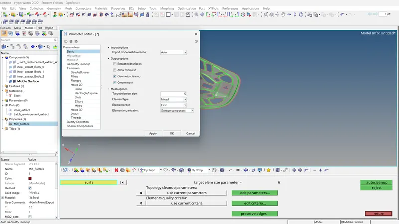
Fig 5: Measuring Parameters
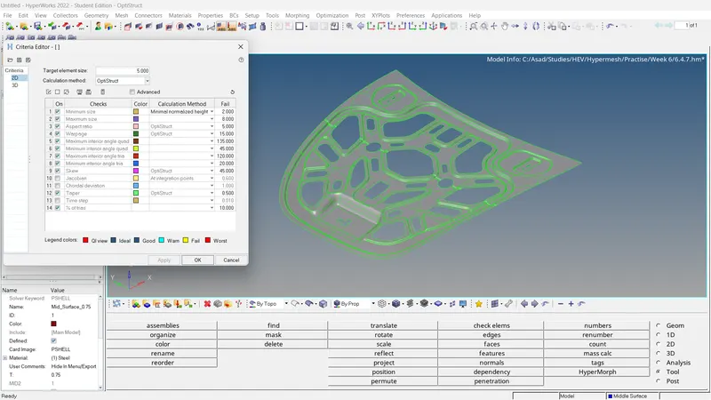
Fig 6: Quality Criteria
Step 4: Meshing the Surface
Because of symmetry, one-half of the mid surface is only needed for the meshing. So the other half will be masked (F5 >> Mask the Unwanted Region). The remaining part meshes using
- 2D >> Automesh >> Select Surface >> Ok.
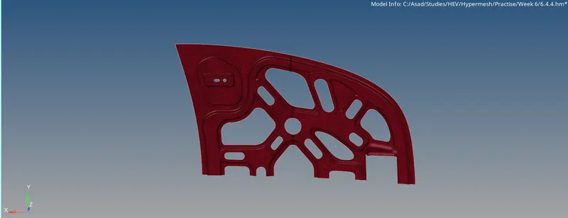
Fig 7: Generated Mesh
The mesh flow should be improved especially in feature areas. For that, there are plenty of tools in the hyper mesh that can be used for the correction of mesh flow. In this case following options are used,
- 2D >> edit element >> Create/Combine/Split
- 2D >> rebuilt >> Select the mesh elements which to be reconstructed.

Fig 8: Edit Elements
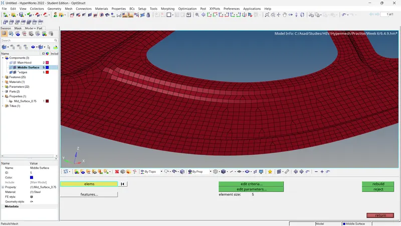
Fig 9: Rebuild Mesh
After correcting the mesh flow, the element quality should be checked.
- 2D >> Quality Index >> Cleanup Tools >> Place nodes/Smooth/Modify holes and washers/Split and Collapse Edge/Swap edge/Drag tria element/node optimise/element optimise/split quad element/combine tria element.
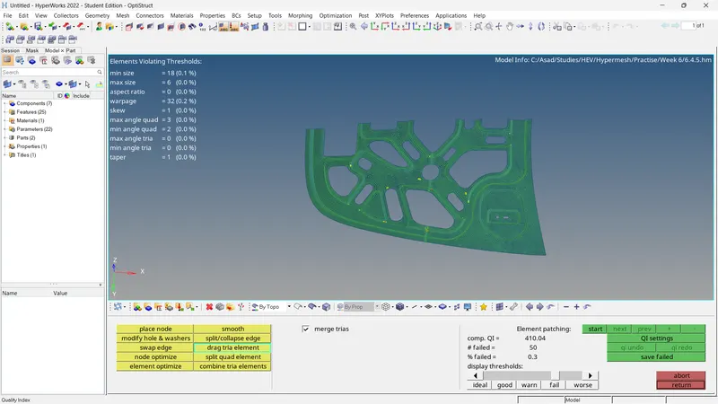
Fig 10: Quality Index
Some of the elements failed for certain quality elements. And those can be addressed by the cleanup tool present in the quality index option.
After meshing, there is a small part of the geometry that affects the symmetry. So it meshed separately. Then mirror one half by,
- Tools >> Reflect >> Elements >> Duplicate >> Select Elements >> Select N1, N2, N3 and B >> Reflect.
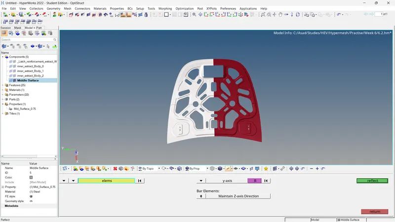
Fig 11: Reflected Elements.
Also, the elements can be checked by following,
- Tools >> Check Elements >> Edit Criteria >> Click To See Plots
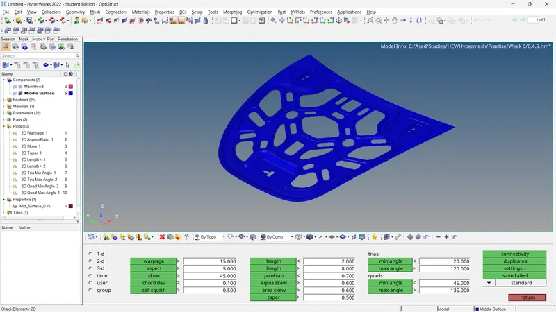
Fig 12: Element Checks And Their Plots
After meshing the remaining faces, the meshing of the mid surface is completed and the elements are qualified for mentioned quality criteria.
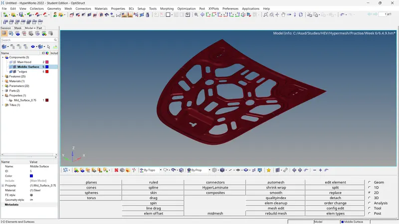
Fig 13: Final Mesh
Step 5: Model Checks
Check For Free Edges And Equivalence
- Tools >> Edges >> Select Elements >> Adjust The Tolerance Value (~0.5) >> Find edges.
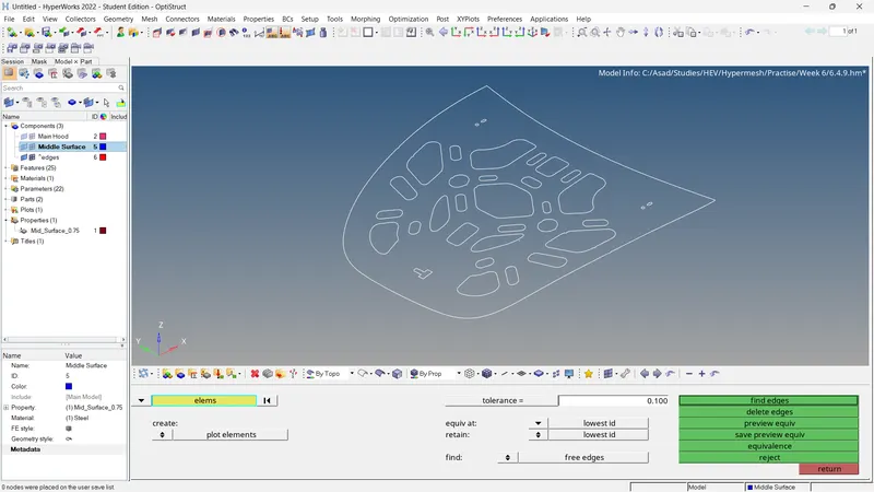
Fig 14: Edges
If edges are present inside the geometry (free edges), it will affect the model. In order to remove the free edges, we can delete edges or recreate elements where free edges are present. Also, we can check for the equivalence to remove the gap between the elements.
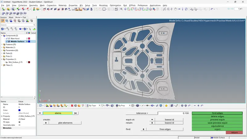
Fig 15: Check For Equivalence
Check For Connectivity and Duplicates
Checking connectivity between elements and the presence of duplicate elements,
For Connectivity
- Tools >> Check Elements >> 2D >> Connectivity
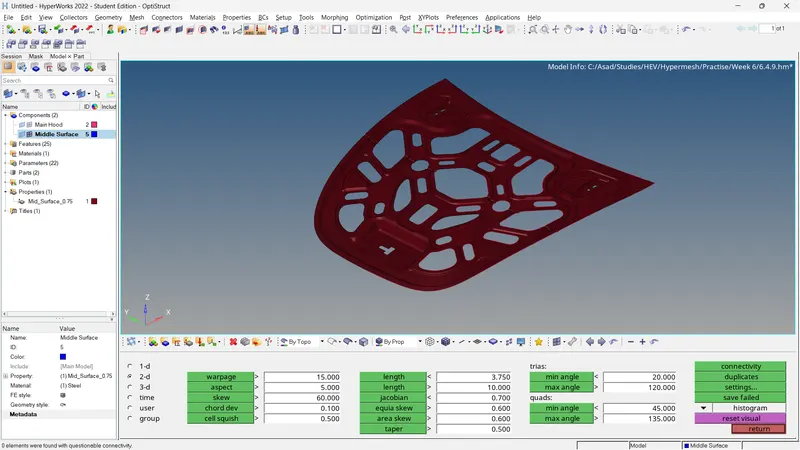
Fig 16: Check For Connectivity
For finding duplicates,
- Tools >> Check Elements >> 2D >> Duplicates
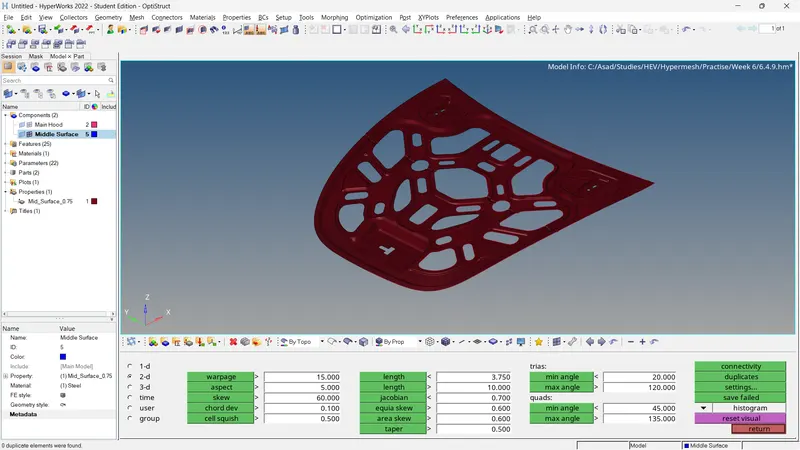
Fig 17: Check For Duplicates.
Check For Normals
- Tools >> Normal >> Elements >> Color Display >> Vector Display >> Size= 100 >> Display.
If any of the vectors have opposite directions, it can be corrected by Using the 'Adjust' option.
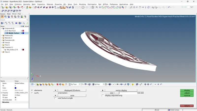
Fig 18: Check For Normals
Check For Penetration and Dependency
For penetration/intersections checks,
- Tools >> Penetration >> Select Elements >> Check
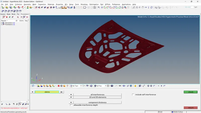
Fig 18: Check For Penetration/Intersections
For dependency checking,
- Tools >> Dependency >> Select Elements >> Dependency
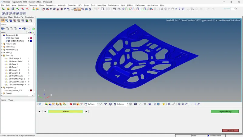
Fig 19: Check For Dependency
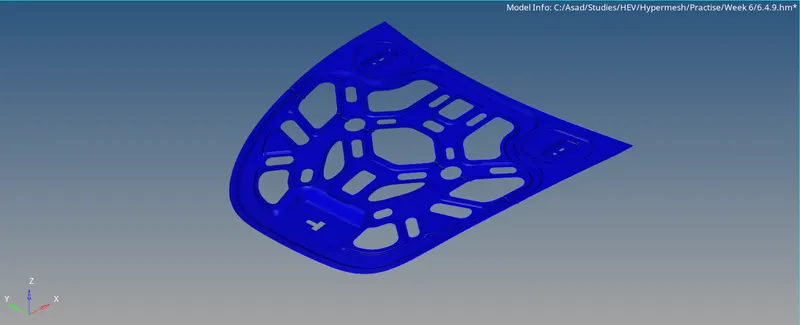
Fig 20: Final Result
4. Conclusion
- The mid surface of the given model is generated and assigned properties, material and add quality criteria and target element lengths.
- The meshing and reconstruction of generated mesh are completed.
- Model checking is finished.
5. Results
- For the given model, the mid-surface is extracted and mesh generated. The generated mesh satisfies the following quality criteria and the model checks are completed.