Week 6-Meshing of Hood Challenge
2D Meshing – Hood
AIM:
To generate a 2D mesh for the given Hood model by taking Mid Surface for each component present in the model after clearing the geometrical errors present in the model followed by meshing with the given Quality Criteria.
PROCEDURE:
Geometry Import:
First, the Hood model has been imported to the Hypermesh software using the IMPORT GEOMETRY option from the IMPORT tab. Figure 1 shows the model imported into hypermesh software.
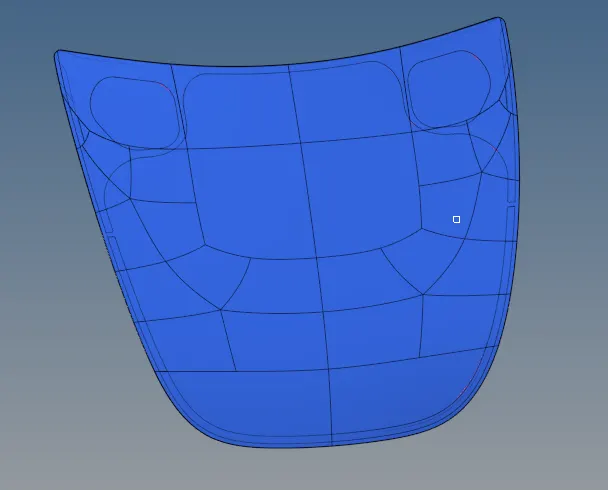
Fig. 1 The Hood model imported into Hypermesh Software
Mid Surface Extraction:
After the model has been imported, Mid Surface of each component has been extracted using the MIDSURFACE-AUTOMID SURFACE-OFFSET+PLANES+SWEEPS option from the GEOMETRY menu. and material and property were created where thickness and material properties were assigned for each respectively. Figure 2 shows the mid surface of the entire model and figures 3 - 10 provide details of the property assigned respectively.
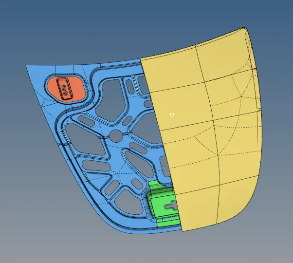
Fig. 2 Mid Surface Extracted for each Component.
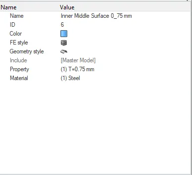
Fig. 3 Properties assigned for Inner Surface with respective thickness.
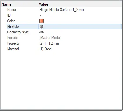
Fig. 4 Properties assigned for Hinge Surface with respective thickness.
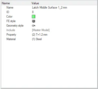
Fig. 5 Properties assigned for Latch Surface with respective thickness.
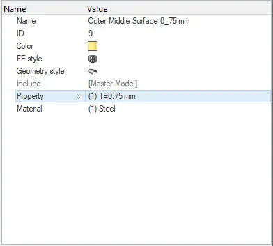
Fig. 6 Properties assigned for Outer Surface with respective thickness.
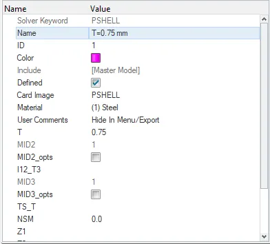
Fig. 7 Properties assigned for the thickness of 0.75mm.
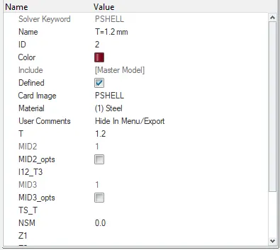
Fig.8 Properties assigned for the thickness of 1.2mm.
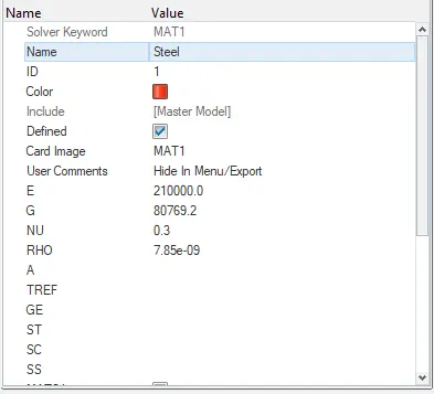
Fig. 9 Material card created.
Geometry Clean-up:
The model has been cleared for geometrical errors using the AUTO CLEAN UP option from the GEOMETRY menu with the default parameters and criteria. The below figure provides a visual aid for the cleared geometry.
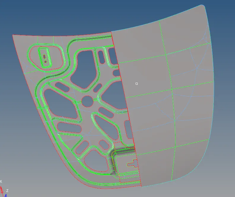
Fig. 10 Auto clean-up performed.
The blue dotted/toggled lines in the model show the geometry clean-up carried out where the unnecessary lines were suppressed to make the model easy to meshing. Since the given hood model is symmetrical, one-half of the model was deleted so that after meshing is completed it can be mirrored.
Meshing:
After Mid Surface Extraction and auto clean-up, meshing has been carried out on the mid-surface with the following mesh parameters shown in figure 11.

Fig. 11 Mesh Parameters.
The mesh was carried out using the AUTOMESH option from the 2D menu bar. Figure 12 shows the mesh created on the mid-surface extracted.
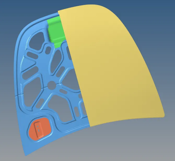
Fig. 12 Mid Surface Meshed.
Quality Checks:
After mid-surface meshed, quality checks have to be performed and the mesh should be free from quality errors. Figure 13 shows the Quality Criteria set for the given model.

Fig. 13 Quality Criteria Check.
The quality check was performed and quality errors were cleared. The mesh model free from quality error is shown the figure 14.
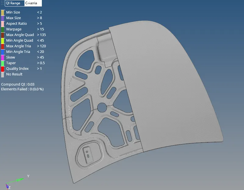
Fig. 14 Quality Checks performed on the mesh.
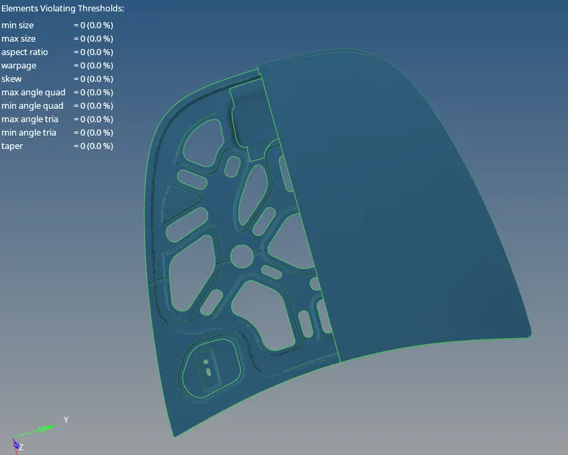
Fig. 15 Quality cleared on the mesh.
After clearing all the quality issues, elements norma; were checked using the NORMAL option from the TOOL menu.
Assigning Thickness: The model has been provided with respective properties namely Thickness, Material, Name, and Ids. Finally, the elements were drawn as solids. Figure 16 shows the mesh elements of the entire model drawn as 2D DETAILED ELEMENT REPRESENTATION to reflect the actual CAD geometry. Figure 17 shows the final model along with CAD Geometry.
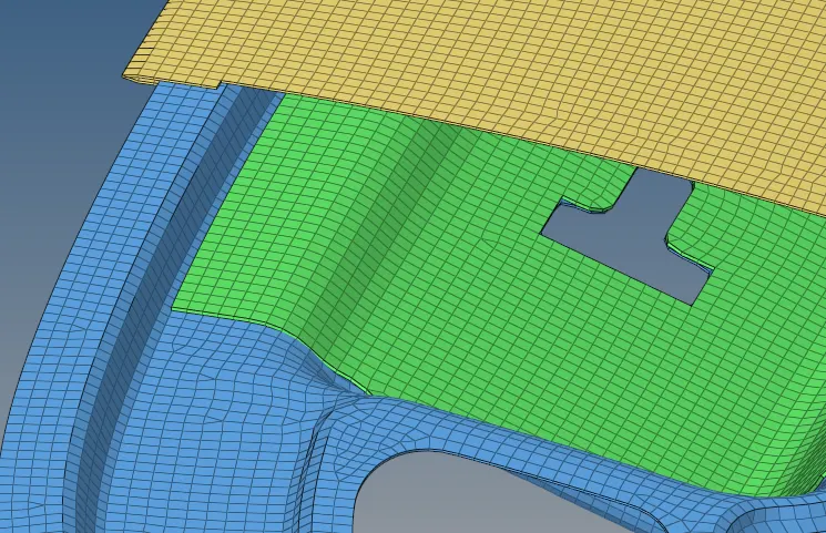
Fig. 16 Elements drawn as 2d detailed element representation.
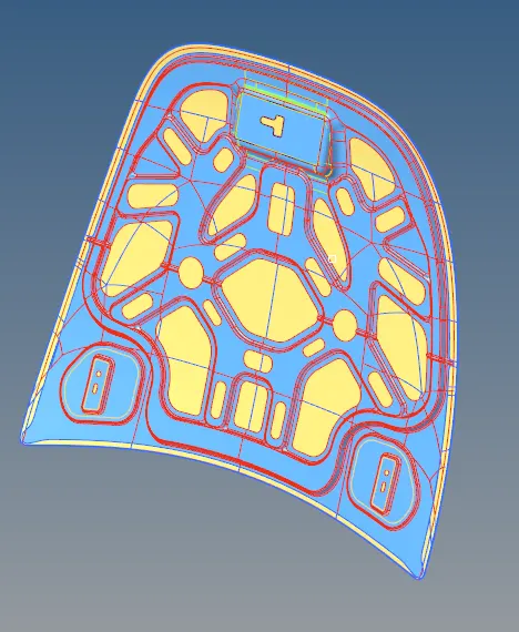
Fig. 17 Final Model with CAD Geometry.
RESULTS:
The given model has been cleared for geometrical errors and meshed for the specified mesh criteria. Then the model has been cleared for all the quality issues for the given quality criteria. Finally, the model is passed for all the given quality parameters.