Week 6-Meshing of Hood Challenge
HOOD MODEL.
AIM: To do geometry clean-up and meshing on hood model.
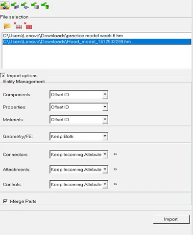
PROCEDURE: 1) Open hyper works desktop student version 2021. Select user interface as Opti struct and import given CAD model.
IMPORT MODEL →IMPORT GEOMETRY→SELECT THE LOCATION (where it is saved) → IMPORT
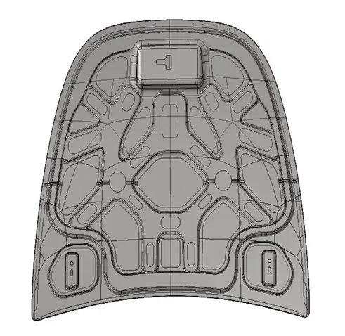
2) Now, we will start modelling. Similar procedure needs to be followed for all the components that is latch, hinge, inner and outer panel.
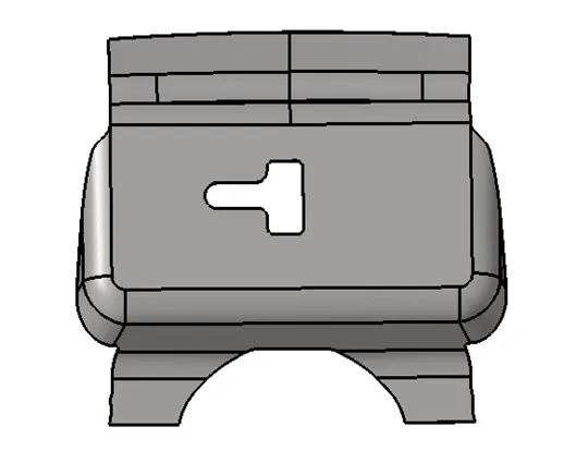
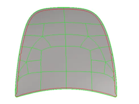
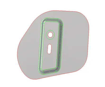
a) Delete the solids
DELETE→SOLIDS→SELECT THE SOLIDS → DELETE ENTITY.
b) Measure the thickness of the components by using distance option. Enable display fixed point option.
GEOMETRY→DISTANCE→ TWO POINTS→ SELECT THE POINTS → DISTANCE.


NOTE: Thickness of hinge and latch part is 1.2 and thickness of inner and outer panel is 0.75.
c) Now, we will generate mid-surface for the components.
GEOMETRY→MID-SURFACE→EXTRACTION OPTION(OFFSET+SWEEP+PLANE) →AUTO EXTRACTION→SELECT SURFACES (DISPLAYED)→EXTRACT.
d) Now, we will create property id and material card. In property card select card image as PSHELL and enter the thickness. Also select the material.
RIGHT CLICK→ CREATE→MATERIAL→SPECIFY NAME (STEEL).
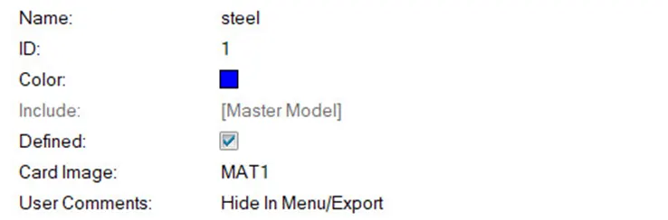
RIGHT CLICK→CREATE→PROPERTY→ENTER THE THICKNESS VALUE →ASSIGN THE MATERIAL →OK.
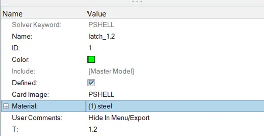
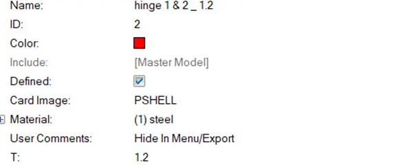
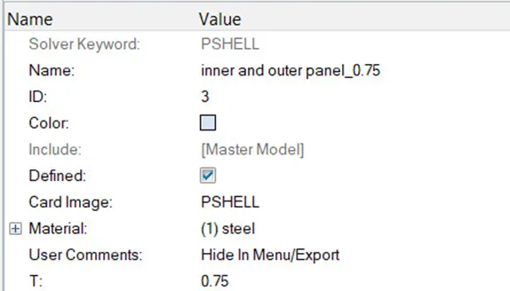
Assign this property and material to the components.
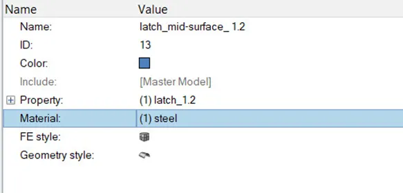
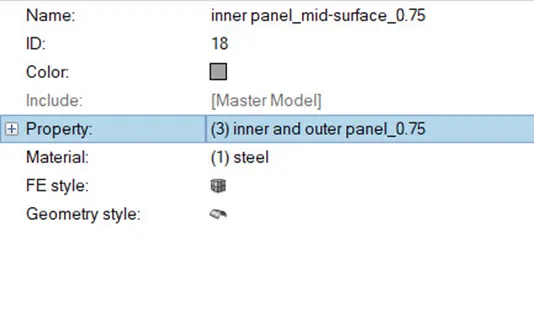
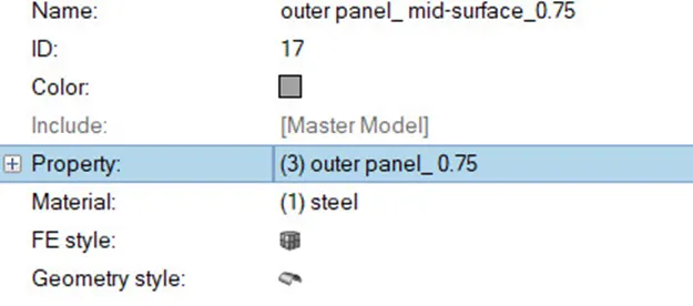
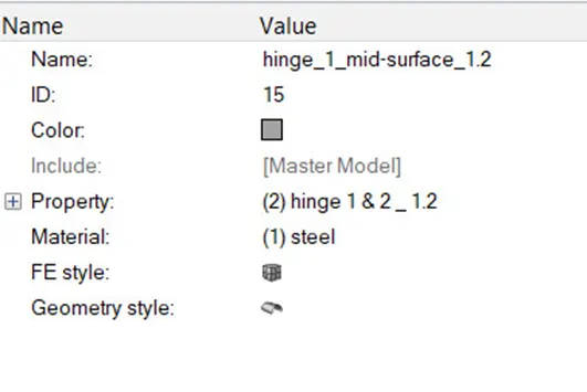
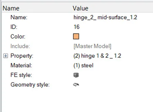
e) Do geometry clean up. Remove unwanted cuts. delete duplicate surfaces and create a surface if any surface is missing.
We can create surface by multiple ways: by using ruled surface option or fill surface etc.
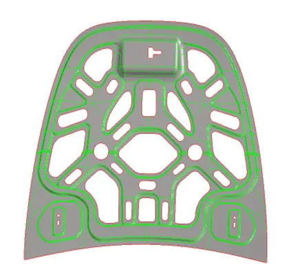
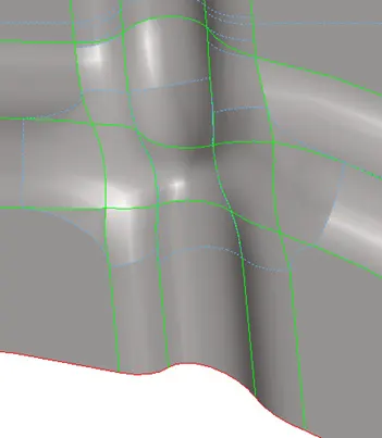
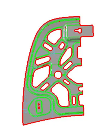
How to do geometry clean up in the critical region in inner panel?
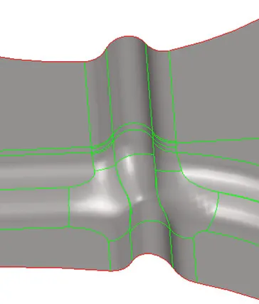
If, we will see in the above image there are lot of unwanted cuts which will result in failure of elements and also improper mesh flow. So, we need to toggle/ suppress few edges and we need to create few edges in order to have good mesh flow.
To remove unwanted cuts, follow the below steps: We can remove the cuts either by toggling it or by supressing it.
By toggle:
GEOM→EDGE EDIT/QUICK EDIT→TOGGLE→SELECT THE LINE WHICH IS NOT REQUIRED.
By suppress:
GEOM→EDGE EDIT→SUPPRESS→SELECT THE LINE WHICH IS NOT REQUIRED.
NOTE: Left click is used to suppress the line whereas right click is used to unsuppressed the line.
To create cuts, there are two options split surf line and split surf node.
Split surf nodes:
GEOM→QUICK EDIT(F11) →SPLIT SURF NODE→SELECT THE NODES →OK
Split surf line:
GEOM→QUICK EDIT→SPLIT SURF LINE→ SELECT THE NODE AND LINE →OK.
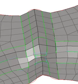
If, we will see in below image unwanted cuts are removed and some cuts are made in order to have parallel mesh flow.
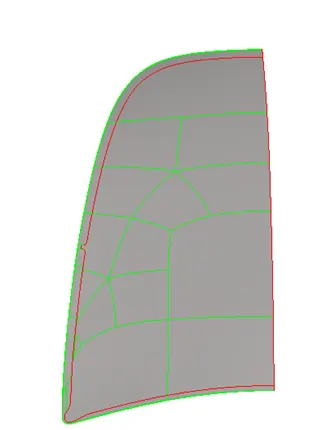
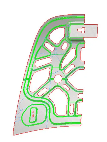
NOTE: If we will observe the half part of inner and outer panel are similar so we will generate mesh only on one half of both the parts and we will reflect it. Delete the half part of both the components.
f) Now, we will generate mesh on the components.
2D→automesh(F12) →select surfaces→ enter target length → create.
g) After mesh generation we need to improve mesh flow.
Steps to be followed to improve mesh flow:
1)Avoid opposite trias.
2) There should not be any rotating quads.
3) There should not be trias at the feature lines.
4) Feature capturing should be proper.
In order, to achieve good mesh flow we use rebuild mesh option:
2D→REBUILD MESH→ELEMENTS→SELECT THE ELEMENT→EDIT PARAMETERS/ CRITERIA→REBUILD.
We improve the mesh flow by using different clean-up tools like drag tria, swap, split etc.
NOTE: after performing any clean up tools use smooth option in order to obtain smooth mesh flow.
To avoid trias at feature line and to eliminate opposite tria we use drag tria option:
2D→QUALITY INDEX→DRAG TRIA→ OK.
To swap tria:
2D→QUALITY INDEX→SELECT THE SIDE OF TRIA WHICH NEEDS TO BE SWAP.
Combine option is used when two tria is sharing one common side. This option converts two tria into single quad.
2D→QUALITY INDEX→COMBINE→SELECT THE SIDE WHICH IS COMMON →COMBINE.
h) Now, we will check whether the elements meet the quality criteria or not. Check element (F10).
Enter the given quality parameters.

g) If the elements are failing to meet the quality criteria’s try to resolve it by using place node, drag tria, element optimization etc.
To resolve issue by using place node option:
2D→QUALITY INDEX →PLACE NODE→CLICK AND DRAG THE NODE→OK
Place node acts like move.
To fix issue using element optimization option:
2D→QUALITY INDEX→ELEMENT OPTIMIZATION→SLECT THE ELEMENT AS WELL AS THE SURROUNDING ELEMENTS.
If we want to project nodes on the feature line:
TOOLS→PROJECT→TO LINE→ALONG VECTOR (NORMAL TO VECTOR) →SELECT THE NODES→SELECT LINE ON WHICH IS TO BE PROJECTED→PROJECT.
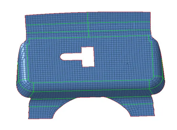
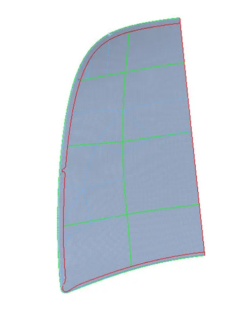
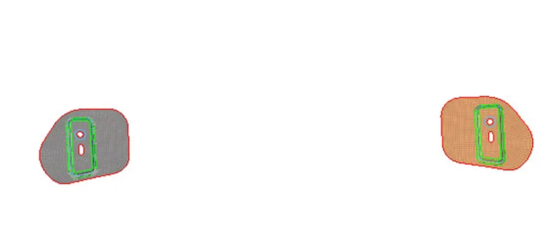
h) There should not be any free edges in between the elements. So, we will check if there are any free edges or not.
To find free edge:
TOOLS/SHIFT+F3→EDGES→ SELECT THE ELEMESNTS→ FIND.
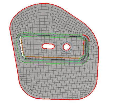
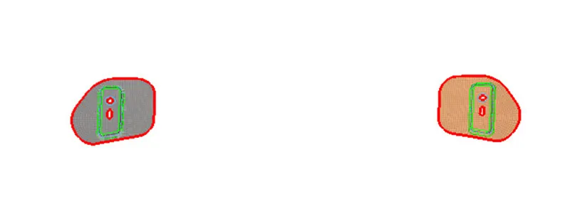
i)If we will observe in the above image there is free edges in between the elements we can use equivalence option or replace node option in order to resolve it.
TOOLS→EDGES→SELECT THE ELEMENTS→PREVIEW EQUIVALENCE→TOLERANCE →EQUIVALANCE.

2D/F3→REPLACE→SELECT THE NODE WICH IS TOBE REPLACED→SELECT THE NODE WITH WHICH THE NODE IS TO BE REPLACED→OK.
NOTE: Delete the free edges after using find option.
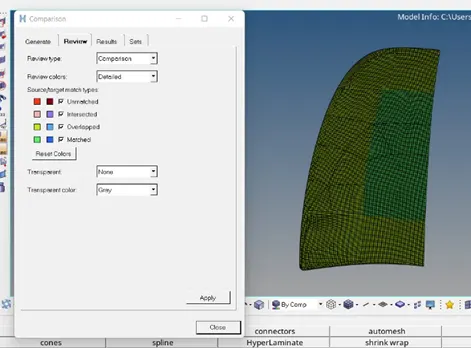
j) Now, we will check whether element is capturing the surface properly or not.
MESH→CHECK→ELEMENT→COMPARISION→SELECT SURFACE→SELECT ELEMENT →RUN
If there is any element not capturing surface properly (red colour elements) then try to resolve it by project option.
k) Now we will check for the normalcy, dependency and penetration.
Normalcy:
TOOLS→NORMALS→ELEMENTS→DISPLAY 2D ELEMENTS→OK
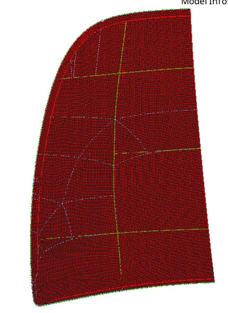

Now if we will observe all the vector are acting in the same direction. If in any region the vector is acting in opposite direction reverse it.
Why we check for normalcy?
While meshing there is a possibility that normalcy of the elements is acting in different direction due inconsistency in surfaces. Hence it needs to be resolved because it directly affects the calculation of physical quantity which acts in that direction. If, the normal doesn’t act in same direction it will give in improper results. Hence, normal of each element should act in same direction.
Now if we will check for dependency and penetration, it will show zero dependency and penetration.
Now, we will reflect the half part of both the inner panel as well as outer panel.
TOOLS→REFLECT→ SLECT THE ELEMENTS→DISPLAYED→ DUPLICATE→SELECT THE NODES N1, N2, N3 AND BASE→ REFLECT.
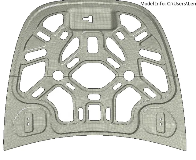
NOTE: Symmetry is performed only for the inner panel because number of nodes is exceeding the limiting value (1 lakh) hyperworks student version doesn’t allow to save file.
LEARNING OUTCOMES: 1) mid-surface creation
2) To deploy mesh.
3) To do geometry clean up manually.
4) To check quality criteria
5) to improve mesh flow using different clean up tools like drag, swap, split etc.
6) Why to check normalcy of elements.
7) To find free edges in between the elements and to resolve it.
CONCLUSION: Hence, mid-surface is created and mesh is deployed on the given hood model.