Week 6-Meshing of Hood Challenge
Meshing of Hood
OBJECTIVE:-
To generate seperate mid-surface and assign thickness for all the model component and mesh them under the quality criteria given below.
Target Element Length = 5 Units
| S.N | Quality Criteria | Value |
| 1 | Aspect Ratio | 5 |
| 2 | Skewness | 45 |
| 3 | Warping | 15 |
| 4 | Taper | 0.5 |
| 5 | Min. Length | 2 Units |
| 6 | Max. Length | 8 Units |
| 7 | Min angle Quad | 45 |
| 8 | Max angle Quad | 135 |
| 9 | Min angle Tria | 20 |
| 10 | Max angle Tria | 120 |
| 10 | Tria % | 10 |
PROCEDURE:-
- Import CAD file to hyperwork environment
- Delete solid surfaces
- Geometry cleanup
- Thickness measurement
- Midsurface extraction
- Property and thickness assigning
- Delete symmetry surfaces
- Defeaturing
- Assign quality criteria
- Meshing
- Quality errors cleanup
- Check for free edges
1) Import CAD file to hyperwork environment:-
Import the .stp model file using File > Import > Geometry > Select file type as STEP > Locate the file > Open > Click on the file > Import command.
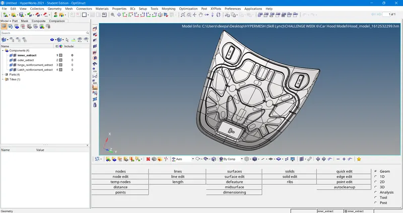
Fig: CAD File Import
2) Delete solid surfaces:-
Now change the Geometry color mode from Auto to By Topo and delete all solid faces for the given component. For deleting the faces, goto Tool > delete > solids > displayed > delete entities.
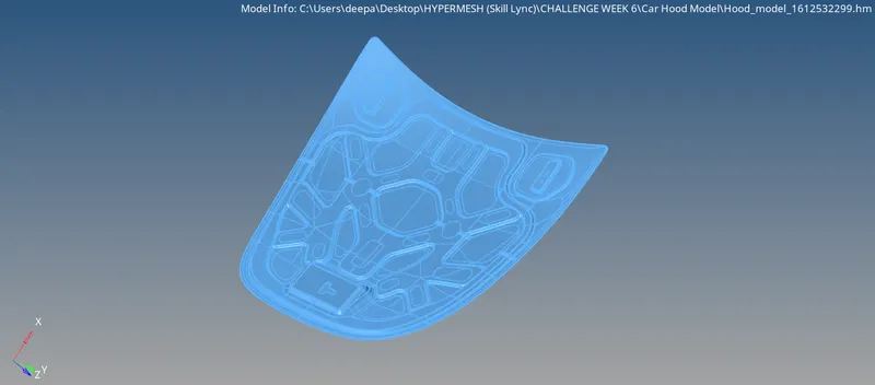
Fig: Solid Model
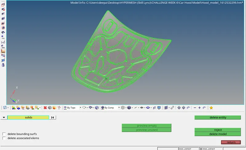
Fig: After Deleting Solids
3) Geometry Cleanup:-
Once the model is imported, move to geometry cleanup just to check if there's any extra surface or free edges or missing surfaces are present or not. For this enable wireframe geometry mode and then try to observe and find irragularities and discontinuities in the model. If found then fix it manually.
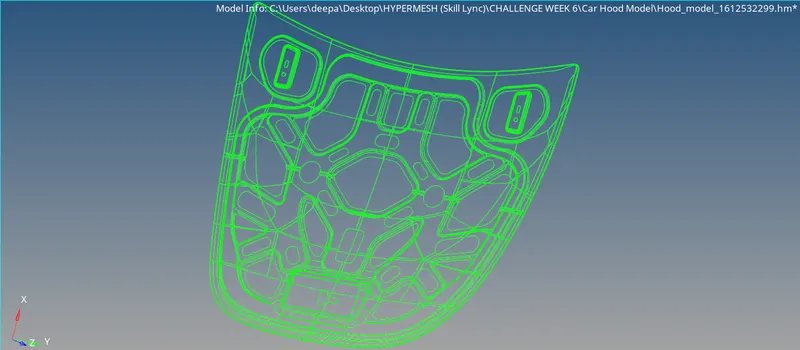
Fig: Wireframe Mode
4) Thickness measurement:-
Measure thickness of all the components using Geom > distance > two points.
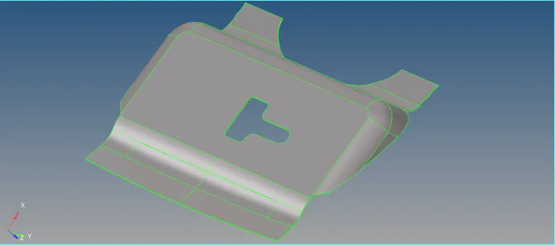
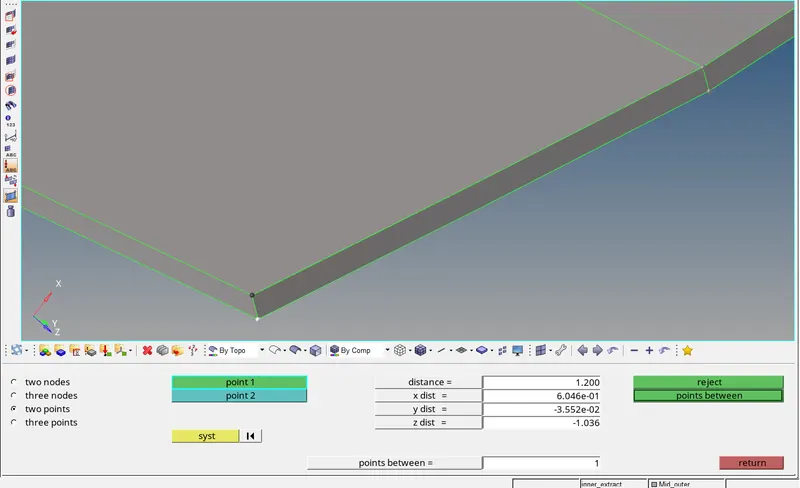
Fig: Latch Thickness Measurement
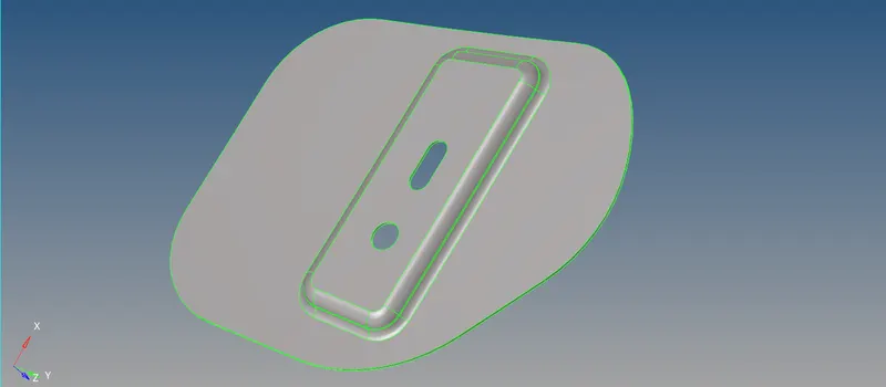
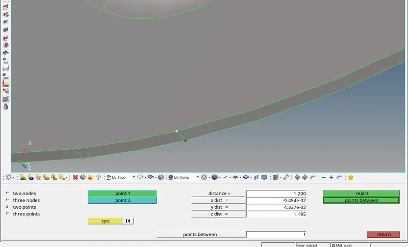
Fig: Hinge Thickness Measurement
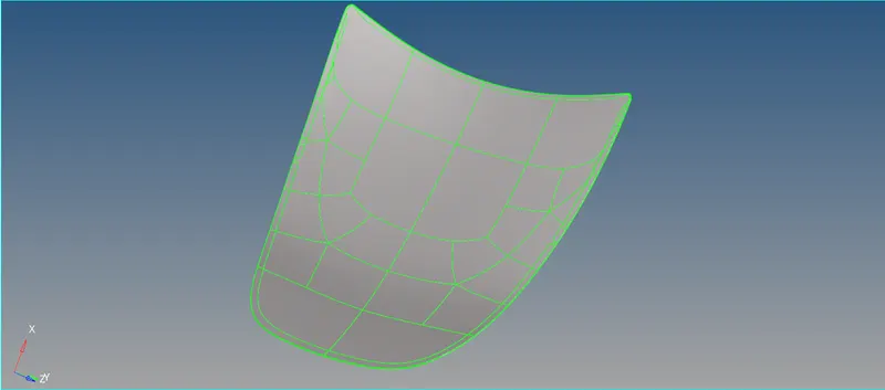
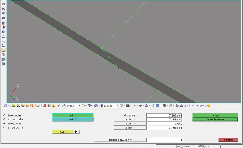
Fig: Outer Panel Thickness Measurement
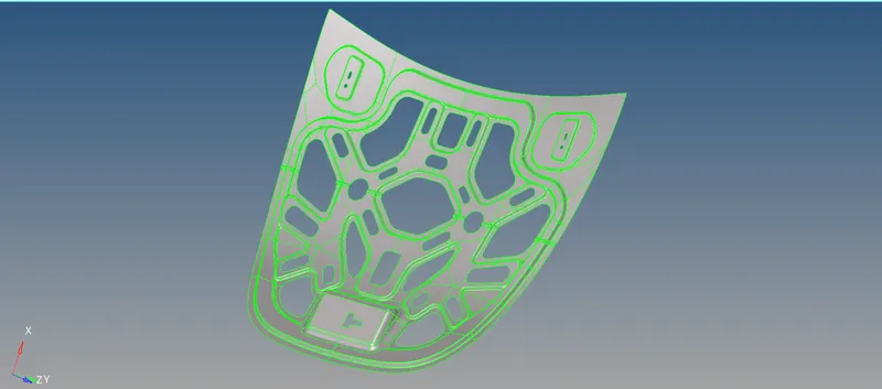
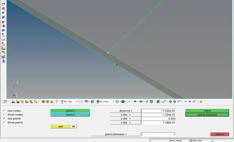
Fig: Inner Panel Thickness Measurement
5) Midsurface Extraction:-
Midsurface extraction is the next step after geometry cleanup and for that, goto Geom > midsurface > extraction options > skin offset > auto extraction > surfs > displayed > extract.
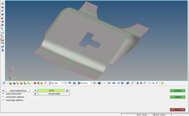
Fig: Latch Midsurface
Extract midsurfaces for all the other components using the same procedure as mentioned above.
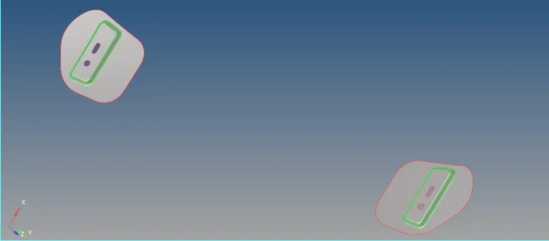
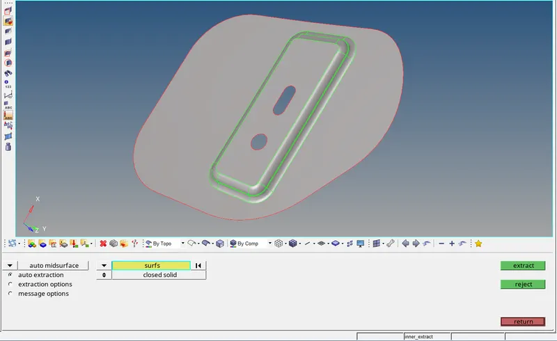
Fig: Hinge Midsurface
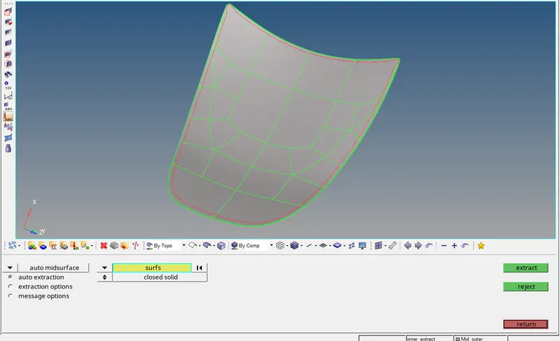
Fig: Outer Panel Midsurface
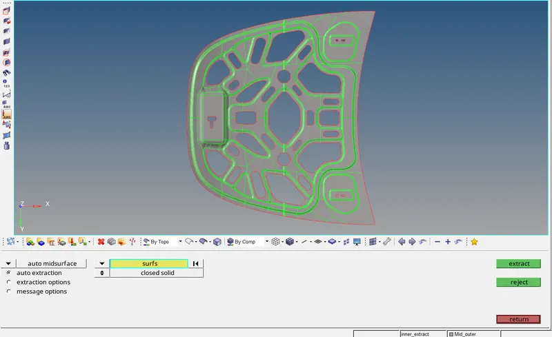
Fig: Inner Panel Midsurface
6) Property and thickness assigning:-
Rename all the midsurface components for convenience and create seperate property cards for all the midsurface components and give thickness to them. Create material card and assign material to all the property cards and then assign property cards to their respective midsurface components.
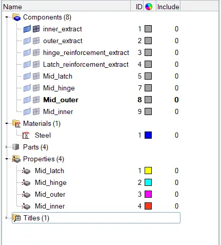
Fig: Components, Material and Properties
7) Delete symmetry surfaces:-
If there's symmetry present in the components, then one half of the component can be deleted to save defeaturing anf meshing time because otherwise we have to defeature and mesh the same half of the component twice which is not a good decision to take so that's why it is wise to delete symmetrical half of the component and work on the other half which can be reflected on the other side later once work is done. Goto Geom > delete > surfs > Select the surfaces > delete entities.
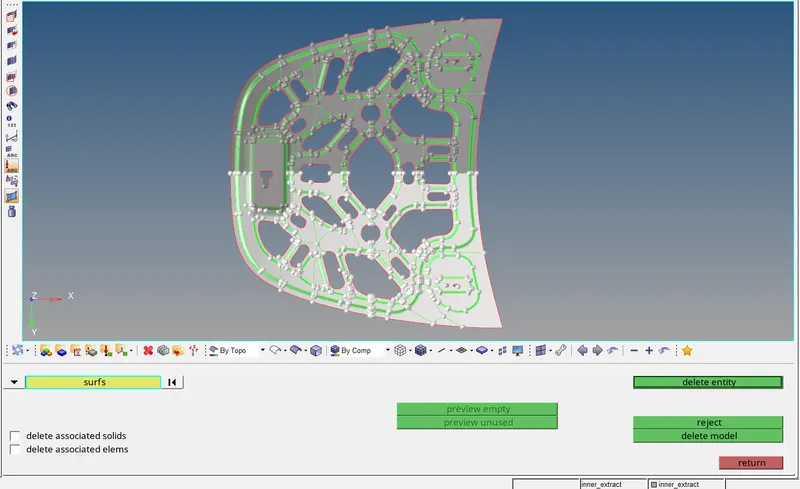
Fig: Surface Selection
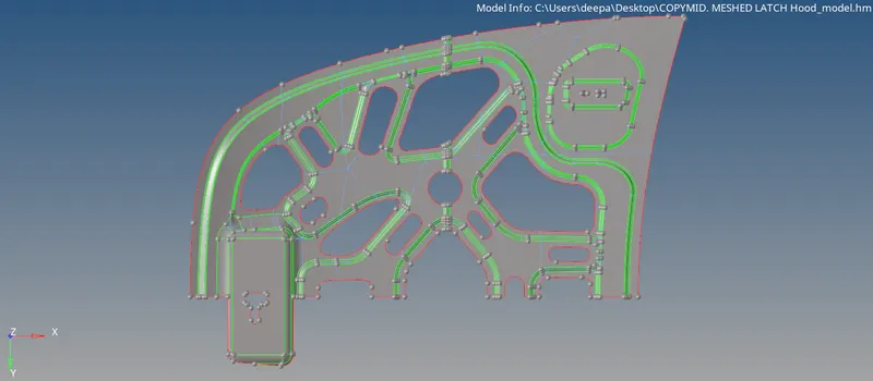
Fig: After Deleting Symmetric Surfaces
8) Defeaturing:-
Defeaturing is nothing but to remove the unnecessary surface radius, holes, edges. Often, the CAD model does contain many detailed features because of manufacturing constraints but very small entities can be a problem. If we have very small faces with sharp angles then failing probabilities of the surface meshing arise. Therefore, we should check the CAD model for very small entities and remove them before trying to create a mesh for it. For this goto Geom > defeature. We can also toggle unnecessary construction lines using Geom > quick edit > toggle command.
The fillet region in outer panel has been failed for quality. So the fillet region has been defeatured for meeting the qulaity criteria values in this case as shown below and mainly outer and inner panel contain many of the defeatured regions.
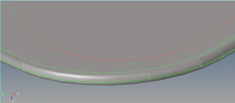
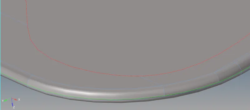
Fig: Defeatured Outer Panel Region
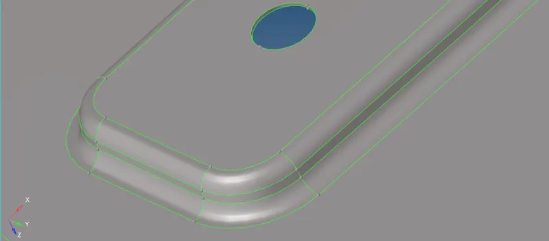
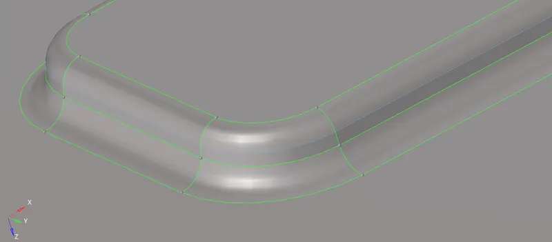
Fig: Defeatured Inner Panel Region
9) Assign quality criteria:-
Every mesh produced has to go through the set of quality check. If quality check fails other steps like boundary conditions and applying loads will not be feasible, So element quality check is performed and no element is allowed to fail under this quality criteria. If the elements fail then these failed elements should be corrected and the elements should matche the quality criteria. To assign quality criteria to the model, go to Preferences > Criteria File Settings.
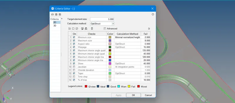
Fig: Quality Criteria
10) Meshing:-
Before meshing, ww have to make sure that quality criteria values are properly entered and quality criteria is applied. Now go to 2D > automesh > surfs > element size - 5 > element type - mixed > mesh. This will mesh the selected target surface with average element length of 5mm. Adjust the number of nodes on the either of sides, to get a good mesh flow and to make sure that rotational quads are not formed on the surface.

Fig: Automesh Panel
11) Quality errors cleanup:-
It is not possible to get perfect mesh flow with no failing elements in the first attempt itself so quality error cleanup is very crucial and essencial step. We have to try for getting as less numbers of trias as it can get and also there should not be any failing element present in the mesh if it is there, then it needs to get resolved. Some cleanup tools like split, swap, combine, replace, drag tria can be used to perform quality error cleanup and for this, go to 2D > qualityindex > cleanup tools.

Fig: Cleanup Tools Panel
Final Meshed Hood Model:-
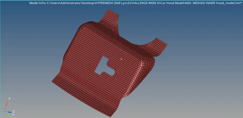
Fig: Meshed Latch
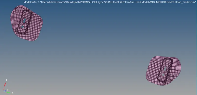
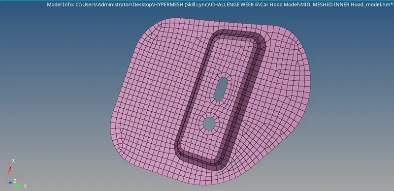
Fig: Meshed Hinge
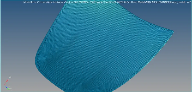
Fig: Meshed Outer Panel
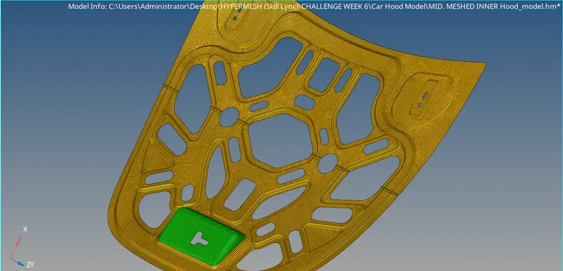
Fig: Meshed Inner Panel
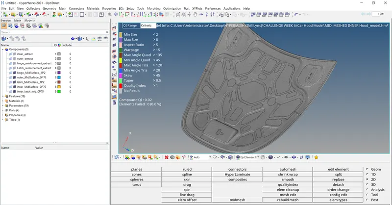
Fig: Final Meshed Hood Model
12) Check for free edges:-
There should not be any free edge remaining through mesh after meshing because having free edges means there is no proper connection between meshing nodes which is not at all acceptable so go to Tool > edges > comp > find edges. Free edges can be recognized by red con, if there is any red con found in between mesh through the meshing other than the areas having only single surface and no shring surface then it is a free edge.
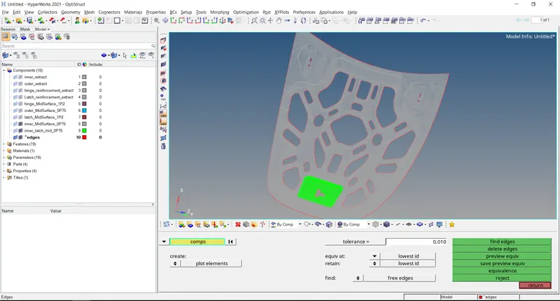
RESULT:-
Successfully perform geometry cleanup, generated mid surface and meshed the given hood model with best mesh flow possible also identified and resolved element failures and learned to assign thickness and property to respective components.