Week 6 - Creating connection for Rear door
AIM :
To Create and Apply different PIDs for different components and to perform suitable connections at different regions of the component.
PROCEDURE :
- In the beginning the given rear door component is imported in the ANSA window and the component is checked for FE Mesh.
- If the FE mesh is available the PID's are created and the whole component is differentiated into various PID's by parts. For example - Door panel, Hinges. Latch etc.
- Next to it the geometry is assessed to assign suitable connectors as the connectors are of various types.
- The usual connectors used in door component are Bolt connectors, Spot weld Connectors, Spotline weld connectors & RBE2 rigid connectors etc.
- The Bolt connectors are used in the Hinge, Spotline weld connectors are used in the Weather strips, RBE2 rigid connectors are used in connecting any rigid parts in the door subsystem.
- For assigning a bolt connector, initially a COG 3D point is created and converted to bolt. Then the properties are assigned to the bolt in the connections manager and the nodes are selected for assigning connectors.
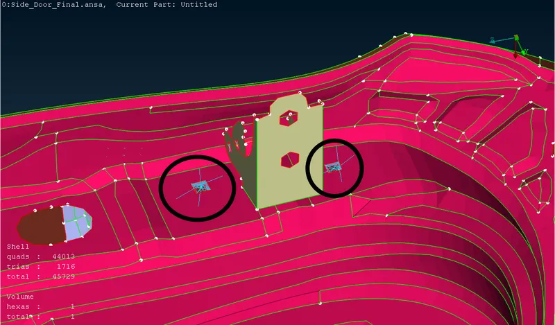
- For assigning a spot weld connector, similarly a 3D point is created and converted to spot weld. Then the properties are assigned to the spot weld in the connections manager and the nodes are selected for assigning connectors. The FE Reg type for spot weld connector is RBE3-HEXA-RBE3.
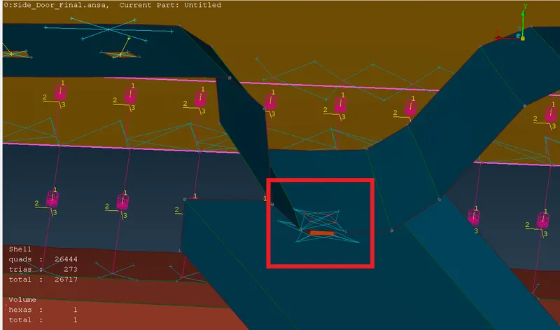
- For assigning a spotline weld connector, the perimeter curve around the FE region is created using FE2curve option and the curve is converted to spotline weld. Then as usual in the connections manager the properties are assigned and the connectors are employed. The FE Reg type for spotline weld connector is RBE3-BUSH-RBE3.
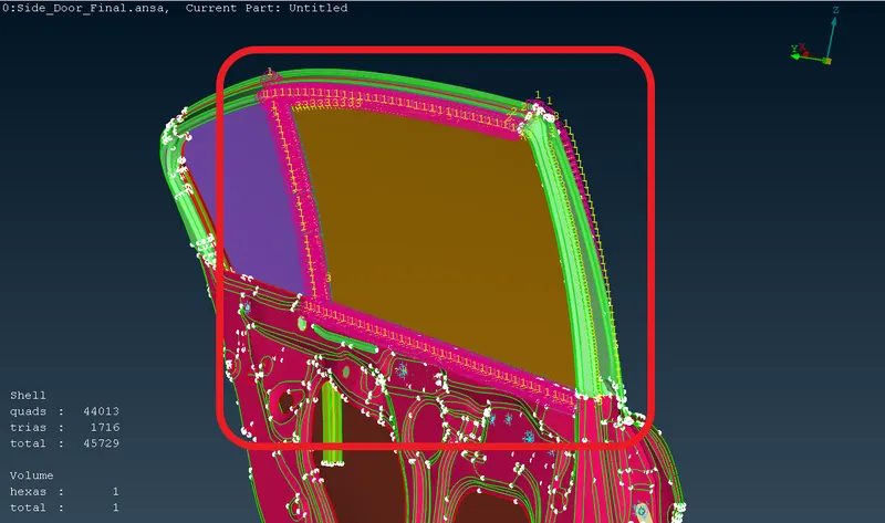
- For assigning a RBE2 rigid connector, the nodes in the region where the connectors are required are selected using the RBE2 option in the NASTRAN Deck. Thus on clickiing OK the connector is employed.
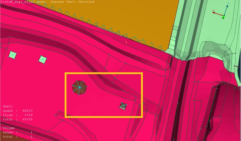
- The RBE2 connectors that are assigned to the join the COG points of the hinges and those connectors that are assigned vertically are set free in rotational z-axis as the doors open and close about the z-axis.
- For the door handle, RBE2 connectors are applied to the two fixing ends and the handle is represented by using the CONM2 connectors where the mass of the handle is to given in tonnes only.
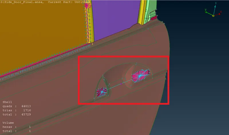
- The regions where the connectors are required are examined and the suitable connectors are used based on the requirements.
- Therefore the given component is perfectly fixed and fit by using various connectors.
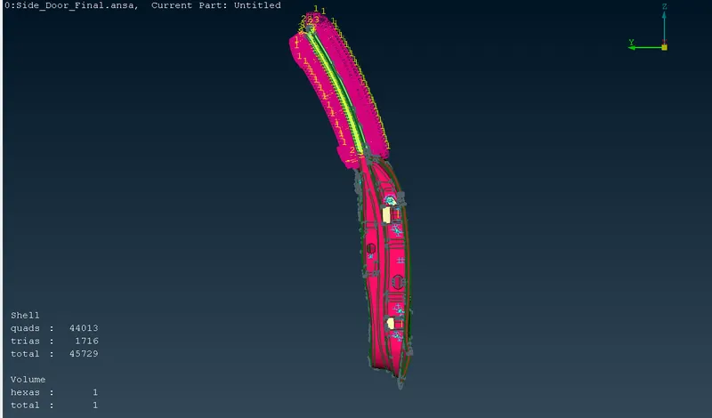
CAD MODEL IMAGES :
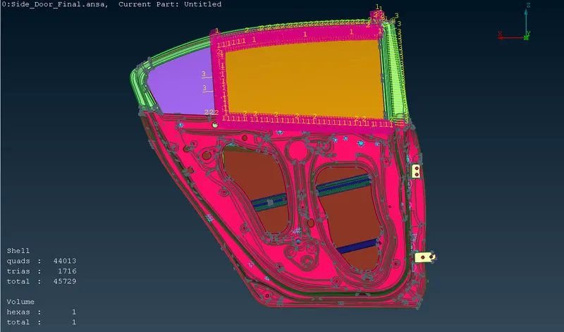
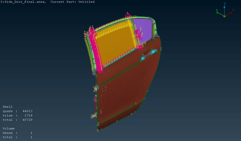
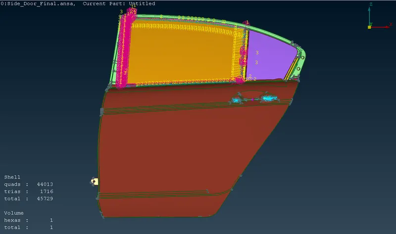
CONCLUSION :
Thus the PID's are created and applied to various components and the suitable connectors are also employed at different regions for the given rear door subsystem.