Week 6 - Creating connection for Rear door
AIM: To create connections to the various subparts in a rear door.To assign PID to each subpart and to provide connections of RBE2,RBE3 HEXA RBE3,OVERLAP SHELL,Y JOINT SHELL etc.


PROCEDURE:1) ASSIGNING OF PROPERTY ID'S TO DIFFERENT SUBPARTS.

  Whole model was in a single PID ,Different pid is assigned to the subparts to make the connection process easier.
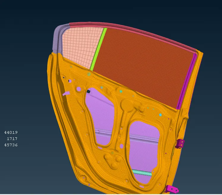
 2. Various connections are created

  Bolt connections, spot welding and seam weldings are utilised to created the connections

2.1 Rigid body element(RBE3)

    This connection restricts the degree of freedom in all directions.
Various methods are used to attain the rigid connections

 2.1.1 Cluster method


       In this method the master node of RBE3 connections of two sufaces are connected to each other.

2.1.2 3D bolt point method

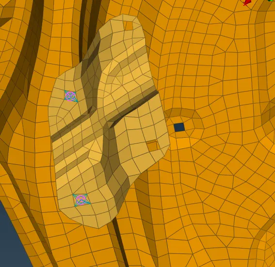
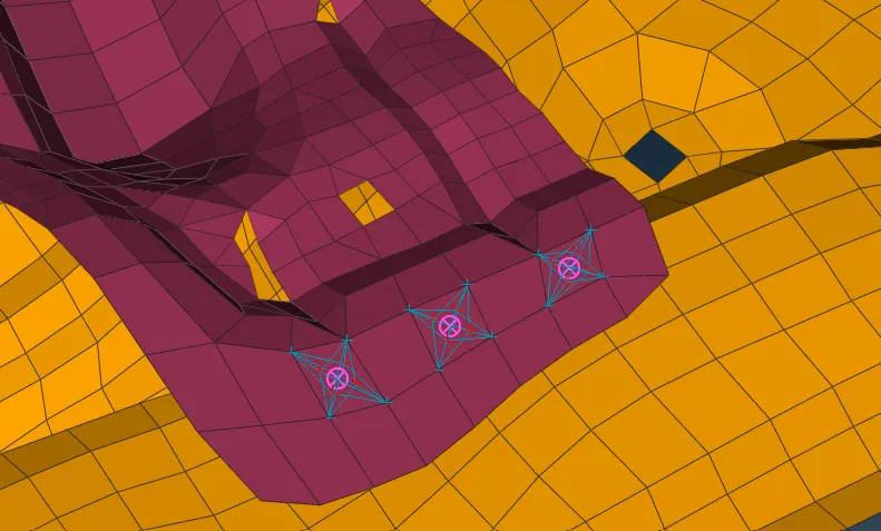
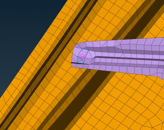
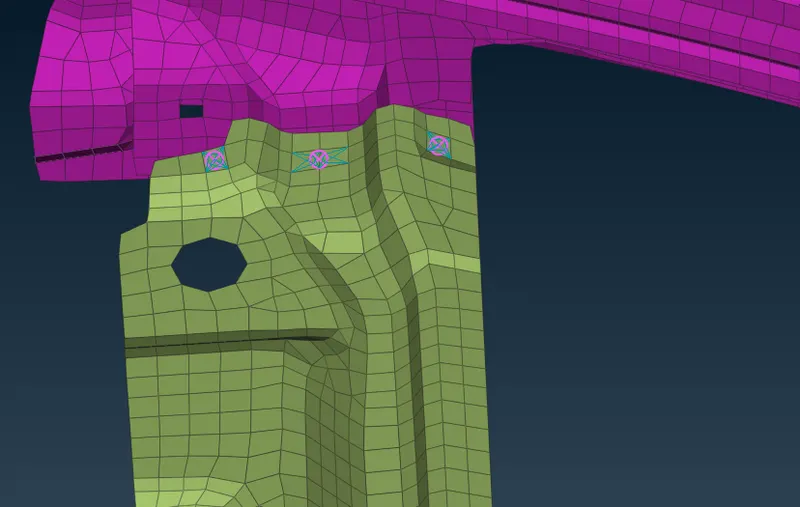
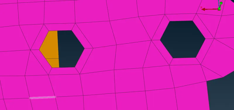
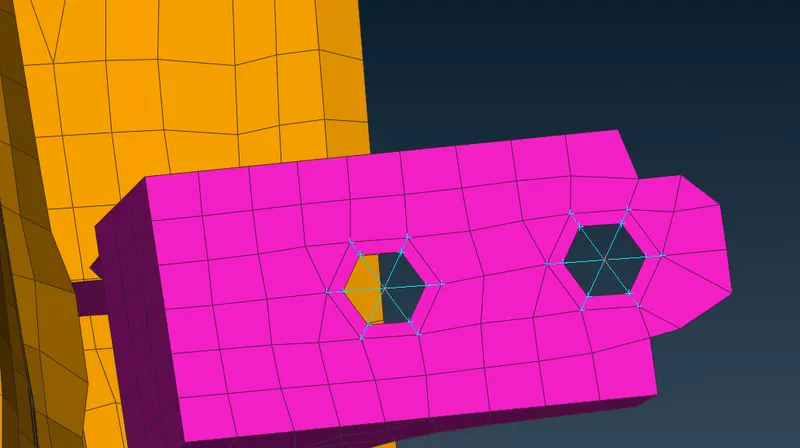
      In this connection is created by providing a COG to the hole and is converted to a bolt point and bolt point to selected to provide a bolt connection fro the connection mananger.

   Zone cut is utilised to provide washer connection to the suface.


 2.2 Seam weld connection

     Seam weld connection is provided to the components which are parellel to each other as well as perpendicular to each other.

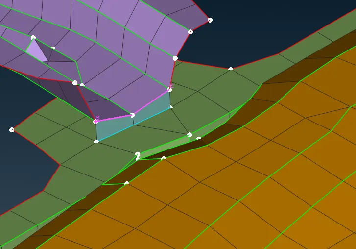
 A curve is made by using cons to curve option and it is connescted together by using multi in connect. Curve is converted to seam line and from connection mananger it is selected to provide the properties of seam welding.For parallel sufaces overlap option is used and for perpendicular surfaces y joint shell option is used.Surfaces are selected from connection manager (P1 AND P2)

 2.3 Spot welding


 A point is made by using COG option. point is converted to seam spot weld and from connection mananger it is selected to provide the properties of spot welding.Surfaces are selected from connection manager (P1 AND P2)

 3 Connection of glass to door

   This connection is done with RBE3 BUSH RBE3
 Curve is created by using cons to curve option and the curve is converted to spot line.The spot line is selected and connection manager is used to provide RBE3 BUSH RBE3 connection and connection parameters are provided.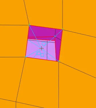
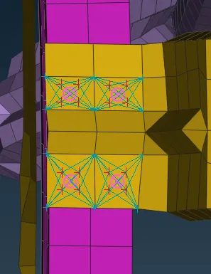
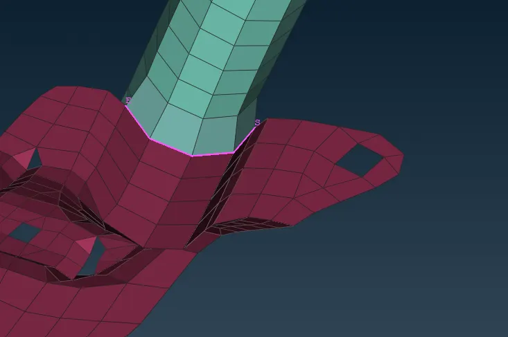
 Connecction of door handle

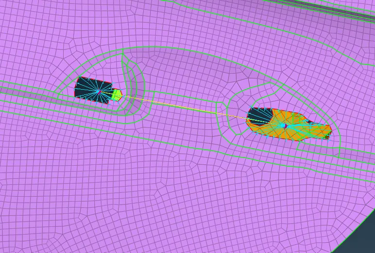
 RBE3 connection are used. The master nodes of two connections are joined and a mass of 100g is provided to the COG of the line connecting the two master nodes.

  since i was not able to get a COG on the line of connection of master nodes,i have assigned two load on the master nodes of RBE3 connection
LEARNING AND OUTCOMES:
Was able to understand different types of connections used in car manufacturing and the method to implement such connections in FE.