Week 6 - Creating connection for Rear door
AIM:
The main objective of this challenge is to create connections for the given rear side door model and store them in a seperate PID's by using some useful tools in ANSA.
PROCEDURE:
There are two steps to be followed for deploying the connections, they are
- Creating new PID's
- Deploying connections.
Creating new PID's:
The input FE model is opened using the command file--->open.
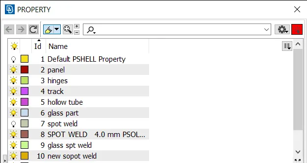
The whole side door is stored in a single PID and that is to be seperated using ther command
TOPO--->faces--->set PID
The purpose for creating PID is during the time of deploying connections the starting and ending point of the connections should be mentioned.
DEPLOYING CONNECTIONS:
For this component, connections like bolt, spotweld, Cbush, Rbe2 and COMiare used.
Bolt connections:
The function of bolt connection is to generates Bolt connections between two or more holes, either of shell or solid mesh. The specified elements of the head and the nut connect the center of the hole to the nodes of selected edges (or the selected nodes) while the body is created between the two centres of each hole.
The command for creating bolt in the hole area is topo-->Points-->On COG option and select edges of the hole to create a point.
After Creating a point, menubar--->assembly--->convert--->3d points and select a point and Select a Bolt connection type.
Then the connection manager tab is opened by the command
assembly--->connection manager---->select the connection.
The above mentioned tab named as connections manager is opened. There the FE representation is selected as bolt connection and options like search distance, zones and DOF for the bolt connections are made.
The top left side of the tab contains the input components for the bolt connections named as p1, p2, p3 are selected. Maximum number of components for the input are upto p4. Finally realise the connection.
The head and the nut are connected with the body of the bolt. Then repeated the same procedure for other entities in the model.
SpotWeld Connection :
The command for the spotweld connection is topo-->Points-->On COG option and select edge of the hole to create a point.
After Creating a point, Go to the Convert option and select a point and Select a Spot Weld Point connection type.
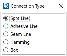
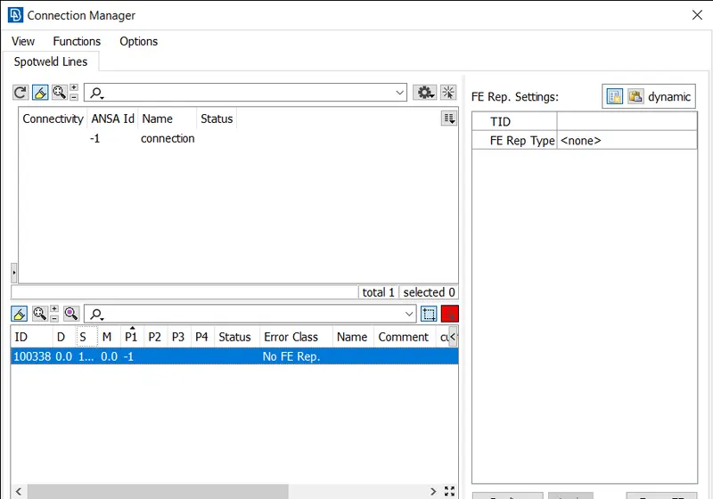
Go to the Connection option and Select the Spot Weld point and Click ok, Connection Manager window will open.
In the Connection Manager window, select the part to make a connection and set it as FE Rep type as RBE3-HEXA-RBE3, Search Distance as 20.
The status bar in the window shows all the details about the coonections made on the selected entities.
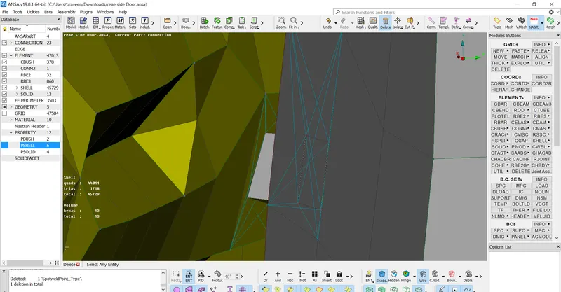
The same procedure is followed for all other entities where the spotweld connections are needed.
CBUSH Connection :
Go to topo-->curves-->cons2curve option and select the edges and create a curve.
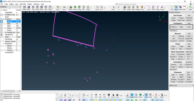
After creating a curve, Go to the Convert-->curves option and select a curve and convert to Spot line. Go to the Assembly--->connections manager option and Select the Spot Weld point and Click ok, Connection Manager window will open.
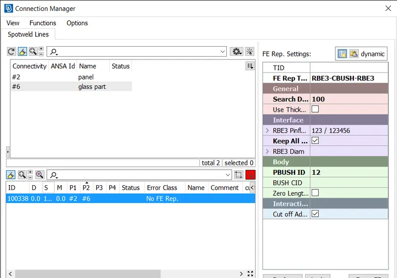
In the Connection Manager window, select the part to make a connection and set it as FE Rep type as RBE3-CBUSH-RBE3, Search Distance as 50 or 100 and Select Keep all Branches option.
In the Connection Manager window, Create a PBUSH ID and assign the values for the property.
After setting all in the connection Manager window, click apply & Realize.
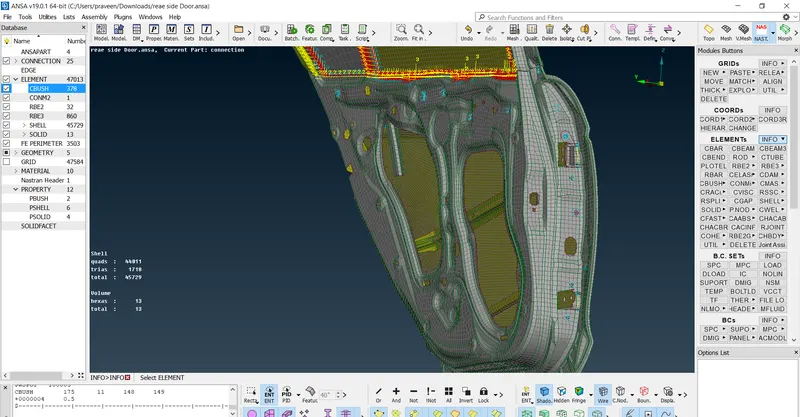
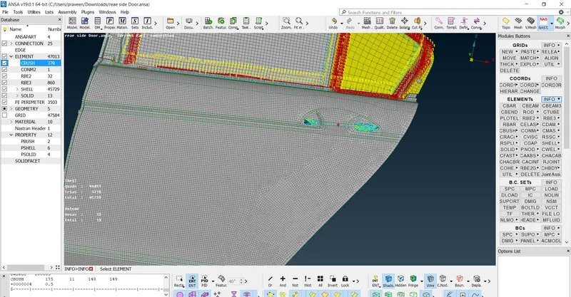
After creating a CBUSH, Open the CBUSH window from Database and convert Orient as with Cord & CID as 0 for all CBUSH.
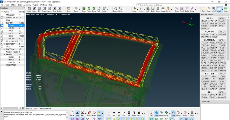
Finally CBUSH will be created along with the Global axis.
RBE2 Connection :
Connecting all other parts by using RBE2 connection.
Go to NASTRAN DECKS-->Elements-->RBE2-->Many nodes Option and select the nodes and Create an RBE2 connection.
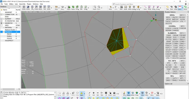
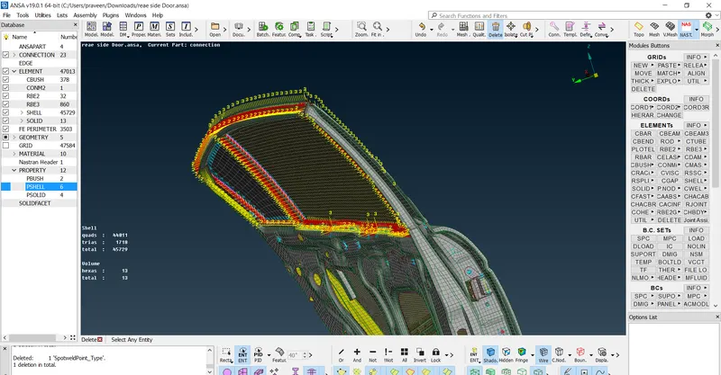
The database shows us all the information about the connections made in the whole model.
COMi Connection:
The connection is mainly represent the mass of the door handle.
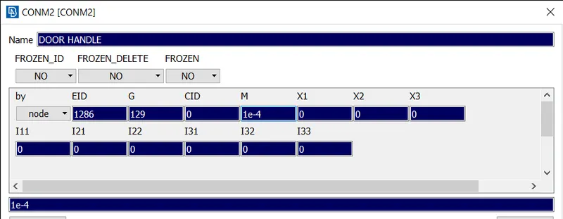
NASTRAN DECK ----> COMi -----> COMM 2 ----> Nodes
By selecting the master node property tab will open
In mass tab represent the mass of the handle in ton and name its for store as property.
FINAL MODEL WITH CONNECTIONS:
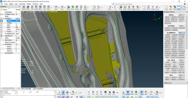
CONCLUSION:
The given component is deployed with the suitable connections and realised the deployed connections successfully in the entities.
LEARNING OUTCOME:
Here i learned the basics of connection on FE model. The outcomes are
- PID SETTING
- CONNECTING MAKING USING DIFFERENT PROCEDURE
- WELDING PROCEDURE
- BUSH CONNECTIONS PROCUDURE
- MASS REPRESENTATION ON SOLID PART