Week - 4 - 2D meshing for Plastic components
AIM
For the given Plastic Bottle Cap model, check for the geometrical errors and take the mid surface by suitable mid surfacing techniques. PID and Thickness assignment has to be done for all the mid surfaces. Mesh the same with the given element Quality criteria.
QUALITY CRITERIA
S.No Quality Criteria value
1 Target/Average length 1
2 Minimum Length 0.5
3 Maximum Length 3
4 Aspect 3
5 Warpage 15
6 Skewness 45
7 Jacobian 0.7
8 Minimum Quad Angle 45
9 Maximum Quad Angle 135
10 Minimum Tria Angle 30
11 Maximum Tria Angle 120
12 Tria Percentage 15
PROCEDURE
GEOMETRY CLEANUP
Import the CAD model into ansa database
Delete the unwanted entities and run the geometry checkups to see the errors present in the model.
As you can see geometric error needle face rectified and corrected by manually or use of autofix present in check-up bar.
After remove topological error we have to refine the geometry by changing the length of the element to 1mm and this is done by using the length button under the perimeters in mesh module.
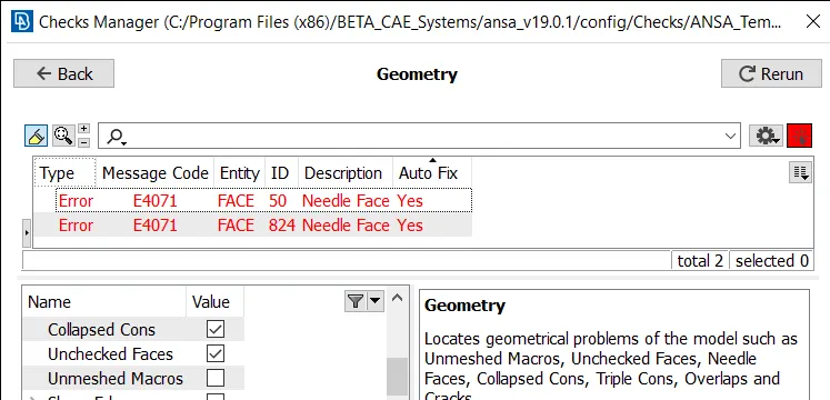
fig. Geometrical error
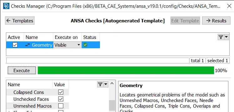
fig. Geometry cleanup
Extracting midsurface
The given model has variable thickness. Hence different midsurface extraction method are needed.
Offset method
Some of the part in the model are subjected to an offset method to extract there midsurface like outer circular face.
Offset under Face option in Topo
Single middle method
Some of the part in the model are subjected to single middle method to extract their midsurface like ribs.
Middle under Face option in TOPO
Curve middle method
Some of the part in the model are subjected to curve middle method to extract their midsurface like teeth.
Middle under curve option in TOPO module to create middle curve.
Extend tool under face option in TOPO module is used to connect the single midsurface part which are seperated from the base to pasted to base geometry for achieving proper midsurface of whole geometry.
Assign New PID to midsurface extracted
After midsurface we have assign a new pid of extracted midsurface.
set PID under Face option
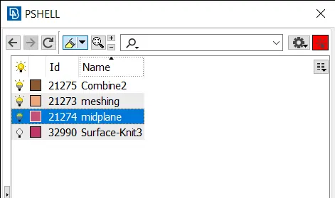
fig. set PID
MESHING
Prior to meshing, mesh parameter and quality criteria were set according to requirement.
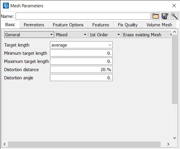
fig. mesh parameter
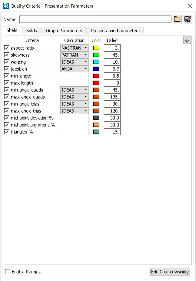
fig. quality criteria
Mesh the model according to given parameter.
Best and Batch meshing algorithm is to be used for meshed the model.
Errror in mesh are corrected by using swap, split, reconstruction, smooth, paste, grid move feature under shell mesh, grid and element options.
Final model
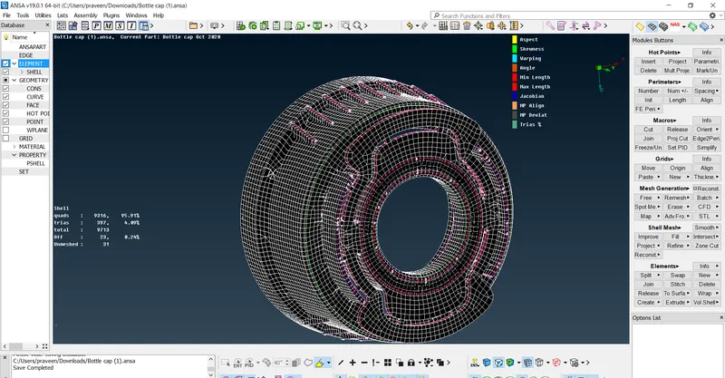
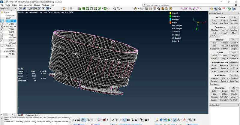
Result
Mid-surface of component is achieved by using different type of manual midsurfacing method and the component is meshed according to given criteria. From this challenge i learned how to mesh varying thickness of any component by using different geometric tool and mesh tools.